EP0972103B1 - Reservoir d'eau pour fer a vapeur, et procede de fabrication d'un tel reservoir - Google Patents
Reservoir d'eau pour fer a vapeur, et procede de fabrication d'un tel reservoir Download PDFInfo
- Publication number
- EP0972103B1 EP0972103B1 EP98963628A EP98963628A EP0972103B1 EP 0972103 B1 EP0972103 B1 EP 0972103B1 EP 98963628 A EP98963628 A EP 98963628A EP 98963628 A EP98963628 A EP 98963628A EP 0972103 B1 EP0972103 B1 EP 0972103B1
- Authority
- EP
- European Patent Office
- Prior art keywords
- shell
- relief
- smoothing iron
- reservoir according
- acting
- Prior art date
- Legal status (The legal status is an assumption and is not a legal conclusion. Google has not performed a legal analysis and makes no representation as to the accuracy of the status listed.)
- Expired - Lifetime
Links
Images


Classifications
-
- D—TEXTILES; PAPER
- D06—TREATMENT OF TEXTILES OR THE LIKE; LAUNDERING; FLEXIBLE MATERIALS NOT OTHERWISE PROVIDED FOR
- D06F—LAUNDERING, DRYING, IRONING, PRESSING OR FOLDING TEXTILE ARTICLES
- D06F75/00—Hand irons
- D06F75/08—Hand irons internally heated by electricity
- D06F75/10—Hand irons internally heated by electricity with means for supplying steam to the article being ironed
- D06F75/14—Hand irons internally heated by electricity with means for supplying steam to the article being ironed the steam being produced from water in a reservoir carried by the iron
Definitions
- the present invention relates to the technical field of steam irons.
- the present invention relates more particularly to steam irons of the type comprising a vaporization chamber and a reservoir intended to receive and store the water before it is injected by various known means such as needles, bushels or pumps in said vaporization chamber for be evaporated there.
- the water tank is generally produced according to one of the following provisions.
- the water tank can constitute an autonomous assembly.
- the iron then comprises a soleplate surmounted by a heating body in which is formed a vaporization chamber, a heat shield placed above the body heating, the water tank then being disposed above said screen.
- the water tank is in this case most often achieved by means of two half shells assembled together so as to form a hollow body.
- This hollow body may contain elements intended for various functions such as by example conduct water to supply pumps, or even contain elements such as water treatment resins.
- the hollow body is designed to so as to leave at least one filling opening for the water.
- this hollow body is made of polypropylene, the two half shells being assembled by welding.
- Such an embodiment also has the disadvantage of multiplying the risks of water leakage failure, either from the construction of the tank, or after a certain time of use. Indeed it is difficult to insure and maintain the seal between the bottom of the polypropylene tank and the vaporization chamber of the made of the relative flexibility of polypropylene at temperatures close to its usage limit.
- the water tank can also be obtained by assembling a half shell forming the upper part of the tank with a part playing both the role of lower part of tank and heat shield.
- the heat shield by its function, is preferably made of a material thermal insulation resistant to temperature such as phenolic resin or polyester.
- the upper part of the tank is most often made of thermoplastic material, preferably transparent, it is therefore excluded to make the connection with the lower part by welding.
- the known solutions consist then to provide a peripheral groove, generally in the heat shield, to interpose in said groove a resin or a liquid silicone, or else seals solids of silicone or rubber type, the latter being obtainable by molding or extrusion.
- Document FR 2 747 404 describes such a solution.
- the assembly can also be completed with one or more screws. None of these solutions only allow a simple and economical assembly.
- This achievement makes it possible to obtain an autonomous and transportable assembly without risk, especially for the rest of the manufacturing process.
- This characteristic facilitates the assembly process of the iron by allowing defer or even remove the screw assembly.
- the or one of the annular conformations formed on the lower half-shell is a skirt, and the or one of the corresponding annular conformations of the upper half shell is a throat.
- the or one of the coatings acting as a seal has a thickness between 0.5 and 5 mm.
- the or one of the coatings acting as a seal is made of EPDM, an abbreviation which designates an ethylene-propylene-diene rubber.
- the lower half-shell comprises a first annular conformation and a second annular conformation adjacent to the first annular conformation
- the upper half-shell has a first annular conformation and a second conformation annular adjacent to the first annular conformation
- the lower half-shell has a peripheral annular conformation and an annular conformation interior
- the upper half-shell has an annular conformation peripheral and an inner annular conformation
- the invention also relates to a method for producing an iron reservoir iron in which the or one of the coatings acting as a seal is obtained by overmolding on the or one of the annular conformations.
- the invention also relates to a method for producing an iron reservoir iron in which the or one of the coatings acting as a seal is obtained with one of the half shells by bi-injection molding.
- This solution optimizes manufacturing costs since one of the half shells and the coating or coatings acting as a seal are obtained in a single injection operation.
- a vent channel avoids the installation of a counter pressure to inside the assembly, detrimental for a device having to work in temperature. It is no longer necessary to mold without shaping the conformation annular of the half shell opposite to that carrying the coating to avoid relatively large fitting efforts that may partially destroy the half shells. This advantage is interesting because the molding without skin complicates and increases the molding operations. There is no need either to oversize the annular conformations so that they can resist the efforts exerted.
- the assembly obtained is less expensive, more resistant and more durable.
- the invention also relates to a method for producing an iron reservoir iron in which one comes to close off the or one of the vent channels after assembly of the upper half shell on the lower half shell.
- vent channels forming free passages for evacuation air during the assembly operation.
- the vent channels can lead into the area of the reservoir intended to receive the water.
- Their shutter avoids the drawbacks linked to the presence of water under the joint.
- the invention also relates to a method for producing an iron reservoir ironing consisting in carrying out the assembly operation of the half shell lower with the upper half shell under partial vacuum.
- the iron tank according to the invention comprises a half shell lower comprising at least one annular conformation.
- the lower half shell 1; 11 features two annular conformations 3, 13; 23, 33, each formed by a groove.
- the iron tank according to the invention also comprises a half upper shell comprising at least one annular conformation, called associated annular conformation, designed to nest in and / or over the corresponding annular conformation of the lower half-shell.
- the upper half shell 2; 12 has two annular conformations 4, 14; 24, 34, each formed by a skirt.
- one of the annular conformations formed on the lower half-shell is a skirt, and the annular conformation corresponding to the upper half shell is a groove.
- the reservoir has two annular conformations 3, 13; 23, 33; 4, 14; 24, 34 on each of the half shells 1; 11; 2; 12, as shown in FIGS.
- This arrangement makes it possible to provide passages 7; 17 in the half upper shell 2; 12 and passages 8; 18 in the lower half-shell 1; 11, for thermostat controls for example.
- FIGS. 1, 2 and 3 show a first embodiment, known as adjacent, in which the lower half-shell 1 and the upper half-shell 2 comprise each a first annular conformation 3; 4 and a second conformation annular 13; 14 adjacent to the first annular conformation 3; 4.
- the annular conformation 3 of the half shell lower 1 defines a cavity 9 forming a reservoir, said cavity comprising a orifice 6 provided for the passage of a needle (not shown in the figures) intended to the steam chamber of an iron.
- the upper half shell 2 shown in FIG. 2 also includes an orifice 10 provided for the passage of the needle.
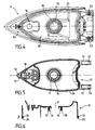
- Figures 4, 5 and 6 show a second embodiment, called concentric, in which the lower half-shell 11 and the half-shell upper 12 each have a peripheral annular conformation 23; 24 and an inner annular conformation 33; 34.
- the peripheral annular conformation 23 and the inner annular conformation 33 of the lower half-shell 11 delimit a cavity 29 forming a reservoir, said cavity comprising an orifice 16 provided for the passage of a needle (not shown in the figures) intended for supplying the steam chamber of an iron.
- the upper half-shell 12 comprises also an orifice 19 provided for the passage of the needle.
- each of the half shells only have an annular conformation, or on the contrary, more than two annular conformations.
- At least one of the conformations is produced with a coating acting as a seal.
- a first coating acting as seal 5 is disposed on the first annular conformation 4 of the upper half-shell 2
- a second covering acting as a seal seal 15 is arranged on the second annular conformation 14 of the half upper shell 2.
- one of the annular conformations of the upper half shell 2 is a groove and not a skirt the covering corresponding is disposed in said groove.
- the skirts forming the annular conformations 4, 14 of the upper half-shell 2 are produced with a coating making seal office 5, 15.
- the skirts forming the annular conformations 24, 34 of the upper half-shell 12 are made with a coating serving as a seal 25, 35.
- each joint 5, 15; 25, 35 is fixed on the end of each conformation associated annular formed by one of the skirts 4, 14; 24, 34.
- Each joint 5, 15; 25, 35 is capable of cooperating by tightening with the annular conformation corresponding formed by one of the grooves 3, 13; 23, 33.
- At least one of the coatings forming seal office is arranged in one of the grooves.
- Said throat can belong to one of the annular conformations of the upper half-shell like the lower half shell.
- one of the coatings acting as a seal 5, 15; 25, 35 has a thickness of between 0.5 and 5 mm. Preferably all said coatings have these characteristics.
- one of the coatings acting as a seal 5, 15; 25, 35 is made of EPDM.
- Other materials, such as silicones or neoprene rubbers are possible, and more generally any material capable of withstanding temperatures of the order of 100 ° C to 150 ° C retaining elastic characteristics and high compressibility.
- the lower half shell 1; 11 is preferably made of a resistant material at temperatures of at least 200 ° C, such as a resin. Such a material also has the advantage of not being a very good conductor of heat.
- the upper half shell 2; 12 is preferably made of material thermoplastic, preferably transparent.
- each associated annular conformation of the upper half-shell is capable of cooperating with the corresponding annular conformation formed in the lower half shell. More particularly, according to the examples of embodiment shown in the figures, each skirt 4, 14; 24, 34 is scheduled to be inserted into the groove 3, 13; 23, 33 corresponding.
- each associated annular conformation such as one of the skirts 4, 14; 24, 34, each seal 5, 15; 25, 35 and each conformation corresponding annular such as one of the grooves 3, 13; 23, 33 are planned to obtain a relative pressure in a direction substantially perpendicular to the direction of assembly.
- This lateral pressure can be all the more important as we are able to assemble the part upper with its seal on the lower part with significant force and this without risking that the seal will move during this operation.
- each groove 3, 13; 23; 33 can have a width of 3 to 10 mm and each of the walls of the joint between skirt and groove a thickness of 0.5 to 5 mm.
- the lower half-shell 1; 11 and the upper half-shell 2; 12 comprise complementary fixing means.
- the upper half shell 2; 12 has tabs 41; 51 each having an orifice 42; 52 likely to come next to housing 43; 53 formed in the lower half-shell 1; 11.
- the orifices 42; 52 and the housing 43; 53 are provided for assembly by screws.
- a different number legs 41; 51 or another method of assembly are also possible.
- the invention also relates to a method for producing an iron reservoir ironing comprising said lower half shells 1; 11 and above 2; 12.
- the method according to the invention consists in producing a coating acting as seal on one of the annular conformations before assembling the lower half shell 1; 11 with the upper half-shell 2; 12. This comes down to irreversibly fix a joint on said conformation.
- Figure 7 shows the lower half shell 11 and the upper half shell 12 before assembly.
- Figure 8 shows the lower half shell 11 and the half upper shell 12 after assembly.
- the method consists in fixing irreversibly a joint 25, 35 on each skirt 24, 34 before assembling the lower half shell 11 with upper half shell 12 inserting each seal 25, 35 in the corresponding groove 23, 33.
- one of the coatings acting as a seal is obtained by overmolding on or in one of the annular conformations.
- each of the coatings acting as a seal is obtained by overmolding on or in one annular conformations.
- each joint 5, 15; 25, 35 is obtained by overmolding on the conformation associated annular 4, 14; 24, 34 of the upper half-shell 2; 12.
- one of the coatings acting as a seal is obtained with one of the half shells by bi-injection molding.
- each of the coatings acting as a seal is obtained with one of the half shells by bi-injection molding.
- each seal 5, 15; 25, 35 is obtained with the upper half-shell 2; 12 by molding bi-injection.
- the reservoir shown in Figures 7 and 8 also has in known manner a filling orifice 20 formed in the upper half-shell 12, as well as orifices 16, 19 formed respectively in the lower half-shells 11 and upper 12, designed to receive a device for injecting water into the chamber vaporization (not shown in the figures).
- a chamber 29 for receiving the liquid is delimited by the annular conformations 23, 33.
- These groove-shaped conformations have a first rim 23 ', 33', arranged on the side of the chamber 29 and a second flange 23 ", 33", arranged on the side opposite the chamber 29.
- the seals 25; 35 during the assembly operation are mounted in compression between the flanges 23 ', 23 "; 33', 33". This provision provides firm support for the two half shells after assembly.
- one of the conformations opposite to that produced with one of the coverings acting as a seal has at least one channel Wind.
- the lower half shell and / or the upper half shell comprises means to prevent air from remaining compressed under the joint (s) after the assembly operation of the two half shells.
- Figure 9 shows a detail of a first embodiment of the means supra.
- the seal 25 mounted on the associated annular conformation 24 is maintained in compression by the first edge 23 'and the second edge 23 "of the groove 23.
- a space 61 is obtained between the seal 25 inserted in the groove 23 and the bottom of said throat.
- a vent channel 62 formed by an orifice made in the bottom of the groove 23 and passing through the half-shell 11 allows communication space 61 with the outside. This arrangement prevents air from remaining compressed under the seal 25.
- the vent channel 62 does not disturb the tightness of the tank since it is isolated from the inside thereof by the wall of the seal.
- several channels 62 are provided for communicating space 61 with the outside. Two to four channels 62 per groove 23 are a good magnitude.
- vent channels 62; 63 do not open into a wall designed to form part of a cavity intended to contain water or steam, such as chamber 29.
- the means provided to prevent air from remaining compressed under the joint (s) 5, 15; 25, 35 after the assembly operation may include a plugging openings of the vent channels 62; 63.
- Figure 11 shows the embodiment shown in Figure 9 supplemented by the obturation of the vent channel 62 by means of a supply of silicone 64.
- FIG. 12 shows the realization presented in figure 10a supplemented by the obturation of the channel 63 at by means of a supply of silicone 65.
- Such a filling makes it possible to obtain more latitude for the choice of the location of channel 62 or channel 63, space 61 being closed and not able to be invaded by water or steam.
- the orifice can also be blocked during the operation assembly thanks to a protrusion formed on the joint.
- the seal 25 has a protrusion 66 provided to close the channel 62 during assembly of the groove 23 with the skirt 24.
- the seal 25 has a lateral protuberance 67 provided for closing the channel 63 during assembly of the groove 23 with the skirt 24.
- Such a closure allows to evacuate a large part of the air present in the space 61 between the joint 25 and the groove 23 during the assembly operation and to avoid the existence of a overpressure in said space. It also has the advantage of not request additional operation.
- the present invention also relates to a method of producing a iron tank consisting in carrying out the assembly operation of the lower half-shell with the upper half-shell under partial vacuum.
- Figure 15 shows a diagram of a device intended for vacuum assembly of the upper half-shell 12 on the lower half-shell 11, in which only the annular conformation 23 and the associated annular conformation 24 comprising the seal 25 are shown.
- a vacuum chamber 76 is applied to a tray 77 on which the lower half-shell is disposed 11.
- a jack 60 comes to assemble the two half-shells 11, 12.
- the tank thus obtained is returned to atmospheric pressure before to release the force of the jack 60 to immediately use the effect of the pressure atmospheric on the assembly of the two half shells.
- the half upper shell can be arranged on a tray having a shape appropriate and the lower half-shell assembled by the jack on the half-shell higher.
- Another method according to the present invention consists in putting in communication with the exterior any space between a joint and an annular conformation. This operation makes it possible to decompress the space or spaces located between each joint and each annular conformation.
- a variant not shown in the figures, consists in creating said free passage, by example by drilling the lower half-shell to put in communication with the outside the space between the seal and the annular conformation, after the assembly operation.
- Another variant consists in providing the channel 63 intended to form a free passage on the joint 25 and not on the conformation 23.
- Such a method may also include carrying out the operation assembly of the lower half shell with the upper half shell under partial vacuum.
- the invention finds its application in the technical field of devices steam appliances and in particular steam irons.
Landscapes
- Engineering & Computer Science (AREA)
- Textile Engineering (AREA)
- Pressure Vessels And Lids Thereof (AREA)
- Preventing Corrosion Or Incrustation Of Metals (AREA)
- Physical Or Chemical Processes And Apparatus (AREA)
- Gasket Seals (AREA)
- Irons (AREA)
- Filling Or Discharging Of Gas Storage Vessels (AREA)
Description
- la figure 1 est une vue schématique de dessus d'un premier exemple de réalisation d'une demi coque inférieure d'un réservoir selon l'invention,
- la figure 2 est une vue schématique de dessous d'un premier exemple de réalisation d'une demi coque supérieure d'un réservoir selon l'invention,
- la figure 3 est une vue schématique de côté en coupe d'un premier exemple de réalisation d'une demi coque supérieure d'un réservoir selon l'invention,
- la figure 4 est une vue schématique de dessus d'un deuxième exemple de réalisation d'une demi coque inférieure d'un réservoir selon l'invention,
- la figure 5 est une vue schématique de dessous d'un deuxième exemple de réalisation d'une demi coque supérieure d'un réservoir selon l'invention,
- la figure 6 est une vue schématique de côté en coupe d'un deuxième exemple de réalisation d'une demi coque supérieure d'un réservoir selon l'invention,
- la figure 7 est une vue de coté en coupe d'un réservoir selon le deuxième exemple de réalisation, avant assemblage,
- la figure 8 est une vue de coté en coupe d'un réservoir selon le deuxième exemple de réalisation, après assemblage,
- la figure 9 est une vue en coupe d'une première réalisation d'un perfectionnement de l'invention,
- les figures 10a et 10b sont deux vues en coupe et de dessus d'une deuxième réalisation d'un perfectionnement de l'invention,
- la figure 11 est une vue en coupe d'une troisième réalisation d'un perfectionnement de l'invention,
- la figure 12 est une vue en coupe d'une quatrième réalisation d'un perfectionnement de l'invention,
- la figure 13 est une vue en coupe d'une cinquième réalisation d'un perfectionnement de l'invention,
- la figure 14 est une vue en coupé d'une sixième réalisation d'un perfectionnement de l'invention,
- la figure 15 est une vue schématique d'un dispositif utilisé pour un procédé selon l'invention.
Claims (20)
- Réservoir de fer à repasser comprenant une demi coque inférieure (1 ; 11) comportant au moins une conformation annulaire (3, 13 ; 23, 33) et une demi coque supérieure (2 ;12) comportant au moins une conformation annulaire (4, 14 ; 24, 34) prévue pour s'imbriquer dans et/ou par dessus la conformation annulaire (3, 13 ; 23, 33) correspondante de la demi coque inférieure (1 ; 11), caractérisé en ce que au moins l'une (4, 14 ; 24, 34) des conformations (3, 13 ; 23, 33 ; 4, 14 ; 24, 34) est réalisée avec un revêtement fixé de manière irréversible et faisant office de joint d'étanchéité (5, 15 ; 25, 35).
- Réservoir de fer à repasser selon la revendication 1, caractérisé en ce que la ou l'une des conformations annulaires (3, 13 ; 23, 33) ménagée sur la demi coque inférieure (1 ; 11) est une gorge, et que la ou l'une des conformations annulaires (4, 14 ; 24, 34) correspondantes de la demi coque supérieure (2 ; 12) est une jupe.
- Réservoir de fer à repasser selon la revendication 1, caractérisé en ce que la ou l'une des conformations annulaires ménagée sur la demi coque inférieure (1 ; 11) est une jupe, et que la ou l'une des conformations annulaires correspondantes de la demi coque supérieure (2 ; 12) est une gorge.
- Réservoir de fer à repasser selon l'une des revendications 1 à 3, caractérisé en ce que le ou l'un des revêtements faisant office de joint d'étanchéité est disposé dans la ou l'une des gorges.
- Réservoir de fer à repasser selon l'une des revendications 1 à 3, caractérisé en ce que le ou l'un des revêtements faisant office de joint d'étanchéité (5, 15 ; 25, 35) est disposé sur la ou l'une des jupes.
- Réservoir de fer à repasser selon l'une des revendications 1 à 5, caractérisé en ce que le ou l'un des revêtements faisant office de joint d'étanchéité (5, 15 ; 25, 35) présente une épaisseur comprise entre 0,5 et 5 mm.
- Réservoir de fer à repasser selon l'une des revendications 1 à 6, caractérisé en ce que le ou l'un des revêtements faisant office de joint d'étanchéité (5, 15 ; 25, 35) est réalisé en EPDM.
- Réservoir de fer à repasser selon l'une des revendications 1 à 7, caractérisé en ce que la demi coque inférieure (1) comporte une première conformation annulaire (3) et une deuxième conformation annulaire (13) adjacente à la première conformation annulaire (3), et que la demi coque supérieure (2) comporte une première conformation annulaire (4) et une deuxième conformation annulaire (14) adjacente à la première conformation annulaire (4).
- Réservoir de fer à repasser selon la revendication 8, caractérisé en ce que un premier revêtement faisant office de joint d'étanchéité (5) est disposé dans ou sur la première conformation annulaire (4) de la demi coque supérieure (2), et un deuxième revêtement faisant office de joint d'étanchéité (15) est disposé dans ou sur la deuxième conformation annulaire (14) de la demi coque supérieure (2).
- Réservoir de fer à repasser selon l'une des revendications 1 à 7, caractérisé en ce que la demi coque inférieure (11) comporte une conformation annulaire périphérique (23) et une conformation annulaire intérieure (33), et que la demi coque supérieure (12) comporte une conformation annulaire périphérique (24) et une conformation annulaire intérieure (34).
- Réservoir de fer à repasser selon la revendication 10, caractérisé en ce qu'un revêtement faisant office de joint d'étanchéité (25) est disposé dans ou sur la conformation annulaire périphérique (24) de la demi coque supérieure (12), et un autre revêtement faisant office de joint d'étanchéité (35) est disposé dans ou sur la conformation annulaire intérieure (34) de la demi coque supérieure (12).
- Réservoir de fer à repasser selon l'une des revendications 1 à 11, caractérisé en ce que la ou l'une (12) des conformations opposée à celle (11) réalisée avec le ou l'un des revêtements faisant office de joint d'étanchéité (25) présente au moins un canal d'évent (62 ; 63).
- Réservoir de fer à repasser selon les revendications 7 et 12, caractérisé en ce que le ou l'un des canaux d'évent (62) part du fond de la gorge et traverse la demi coque (11).
- Réservoir de fer à repasser selon les revendications 7 et 12, caractérisé en ce que le ou l'un des canaux d'évent (63) est ménagé dans l'une des parois verticales de la gorge.
- Réservoir de fer à repasser selon la revendication 12, caractérisé en ce que le ou l'un (25) des revêtements faisant office de joint d'étanchéité présente une sur épaisseur (66 ; 67) prévue pour venir obturer le ou l'un des canaux d'évent (62 ; 63).
- Procédé de réalisation d'un réservoir de fer à repasser selon l'une des revendications 1 à 15 caractérisé en ce qu'il comporte une opération d'assemblage définitif irréversible, de l'un des revêtements faisant office de joint d'étanchéité (5, 15; 25, 35) sur la ou l'une des conformations annulaires (4, 14 ; 24, 34).
- Procédé de réalisation d'un réservoir de fer à repasser selon la revendication 16 caractérisé en ce que l'opération d'assemblage définitif est un surmoulage classique ou obtenu lors d'une opération de moulage bi-injection.
- Procédé de réalisation d'un réservoir de fer à repasser selon la revendication 16 caractérisé en ce qu'il comporte une opération de moulage ou d'extrusion classique de l'un des revêtements faisant office de joint d'étanchéité (5, 15 ; 25, 35) et en ce que l'opération d'assemblage définitif est une opération de collage dudit joint avec l'une (2; 12) des demi coques
- Procédé de réalisation d'un réservoir de fer à repasser selon la revendication 16, caractérisé en ce qu'il comporte une opération d'obturation du ou d'un des canaux d'évent après assemblage de la demi coque supérieure (12) sur la demi coque inférieure (11).
- Procédé de réalisation d'un réservoir de fer à repasser selon la revendication 16, caractérisé en ce qu'il comporte une opération d'assemblage de la demi coque inférieure avec la demi coque supérieure réalisée sous vide partiel.
Applications Claiming Priority (5)
| Application Number | Priority Date | Filing Date | Title |
|---|---|---|---|
| FR9800945A FR2774102B1 (fr) | 1998-01-23 | 1998-01-23 | Procede de fabrication d'un reservoir d'eau pour fer a vapeur, et reservoir obtenu par un tel procede |
| FR9800945 | 1998-01-23 | ||
| FR9807473 | 1998-06-10 | ||
| FR9807473A FR2774103B1 (fr) | 1998-01-23 | 1998-06-10 | Reservoir d'eau pour fer a vapeur, et procede de fabrication d'un tel reservoir |
| PCT/FR1998/002870 WO1999037850A1 (fr) | 1998-01-23 | 1998-12-24 | Reservoir d'eau pour fer a vapeur, et procede de fabrication d'un tel reservoir |
Publications (2)
| Publication Number | Publication Date |
|---|---|
| EP0972103A1 EP0972103A1 (fr) | 2000-01-19 |
| EP0972103B1 true EP0972103B1 (fr) | 2003-04-09 |
Family
ID=26234093
Family Applications (1)
| Application Number | Title | Priority Date | Filing Date |
|---|---|---|---|
| EP98963628A Expired - Lifetime EP0972103B1 (fr) | 1998-01-23 | 1998-12-24 | Reservoir d'eau pour fer a vapeur, et procede de fabrication d'un tel reservoir |
Country Status (12)
| Country | Link |
|---|---|
| US (1) | US6151815A (fr) |
| EP (1) | EP0972103B1 (fr) |
| AT (1) | ATE237018T1 (fr) |
| AU (1) | AU1883399A (fr) |
| BR (1) | BR9807617A (fr) |
| CA (1) | CA2283715A1 (fr) |
| DE (1) | DE69813197T2 (fr) |
| ES (1) | ES2196644T3 (fr) |
| FR (1) | FR2774103B1 (fr) |
| HK (1) | HK1022726A1 (fr) |
| PT (1) | PT972103E (fr) |
| WO (1) | WO1999037850A1 (fr) |
Families Citing this family (7)
| Publication number | Priority date | Publication date | Assignee | Title |
|---|---|---|---|---|
| FR2785915B1 (fr) * | 1998-11-17 | 2001-02-02 | Seb Sa | Procede d'obtention d'un reservoir d'eau en deux parties et reservoir selon ce procede |
| FR2852028B1 (fr) * | 2003-03-03 | 2005-06-24 | Seb Sa | Fer a vapeur avec jupe plastique enfermant la chambre de vaporisation |
| WO2005038706A2 (fr) | 2003-10-14 | 2005-04-28 | Amfit, Inc. | Procede de saisie et de reproduction d'un contour 3d |
| CN101389802B (zh) * | 2006-02-23 | 2013-07-10 | 皇家飞利浦电子股份有限公司 | 熨烫套 |
| FR2912428B1 (fr) * | 2007-02-12 | 2009-03-06 | Rowenta Werke Gmbh | Appareil de repassage comportant un cordon de vapeur muni d'un connecteur rotatif |
| EP2650615B2 (fr) * | 2012-04-11 | 2024-05-15 | Electrolux Home Products Corporation N.V. | Four pour la cuisson de produits alimentaires |
| ES2529598B1 (es) * | 2013-08-22 | 2015-12-03 | Bsh Electrodomésticos España, S.A. | Plancha a vapor |
Family Cites Families (13)
| Publication number | Priority date | Publication date | Assignee | Title |
|---|---|---|---|---|
| GB491759A (en) * | 1937-10-08 | 1938-09-08 | Ernest Fredrick Pohl | Pressing irons |
| US2883778A (en) * | 1954-03-23 | 1959-04-28 | Kistner Merrill Miller | Steam iron |
| US4115935A (en) * | 1977-05-16 | 1978-09-26 | General Electric Company | Plastic steam iron |
| US4190762A (en) * | 1978-07-17 | 1980-02-26 | General Electric Company | Adjustable gap electrode arrangement for electrolytically heated steam iron |
| US4532411A (en) * | 1982-03-19 | 1985-07-30 | Marc Terraillon | Electric fabric steaming appliance having a detachable metallic sole-plate |
| IT8211695V0 (it) * | 1982-06-10 | 1982-06-10 | Biancalani Mauro | Ferro da stiro a vapore con vaschetta per l'acqua disposta posteriormente |
| US4686352B1 (en) * | 1984-04-27 | 1993-12-14 | Sunbeam Corporation | Electronic pressing iron |
| US5071143A (en) * | 1989-07-06 | 1991-12-10 | Ta Mfg. Co. | Sealing arrangement for bulkhead |
| US5222746A (en) * | 1990-03-07 | 1993-06-29 | Brian Technics | Protective bellows for universal joints allowing rapid installation |
| FR2691176B1 (fr) * | 1992-05-15 | 1995-09-08 | Moulinex Sa | Fer a repasser electrique a vapeur. |
| US5398424A (en) * | 1992-09-25 | 1995-03-21 | Corcoran; Jerry A. | Towel having a protective covering for use in wet weather |
| US5671927A (en) * | 1995-04-07 | 1997-09-30 | Dana Corporation | Gasket assembly with sealing member having main body with integral tabs |
| FR2747404B1 (fr) * | 1996-04-12 | 1999-10-01 | Moulinex Sa | Fer a repasser et procede d'assemblage d'un tel fer |
-
1998
- 1998-06-10 FR FR9807473A patent/FR2774103B1/fr not_active Expired - Fee Related
- 1998-12-24 CA CA002283715A patent/CA2283715A1/fr not_active Abandoned
- 1998-12-24 BR BR9807617-5A patent/BR9807617A/pt not_active IP Right Cessation
- 1998-12-24 US US09/381,583 patent/US6151815A/en not_active Expired - Fee Related
- 1998-12-24 EP EP98963628A patent/EP0972103B1/fr not_active Expired - Lifetime
- 1998-12-24 AT AT98963628T patent/ATE237018T1/de not_active IP Right Cessation
- 1998-12-24 WO PCT/FR1998/002870 patent/WO1999037850A1/fr active IP Right Grant
- 1998-12-24 AU AU18833/99A patent/AU1883399A/en not_active Abandoned
- 1998-12-24 PT PT98963628T patent/PT972103E/pt unknown
- 1998-12-24 DE DE69813197T patent/DE69813197T2/de not_active Expired - Fee Related
- 1998-12-24 ES ES98963628T patent/ES2196644T3/es not_active Expired - Lifetime
-
2000
- 2000-03-03 HK HK00101371A patent/HK1022726A1/xx not_active IP Right Cessation
Also Published As
| Publication number | Publication date |
|---|---|
| AU1883399A (en) | 1999-08-09 |
| US6151815A (en) | 2000-11-28 |
| EP0972103A1 (fr) | 2000-01-19 |
| FR2774103A1 (fr) | 1999-07-30 |
| HK1022726A1 (en) | 2000-08-18 |
| ATE237018T1 (de) | 2003-04-15 |
| BR9807617A (pt) | 2000-02-22 |
| WO1999037850A1 (fr) | 1999-07-29 |
| FR2774103B1 (fr) | 2000-03-03 |
| PT972103E (pt) | 2003-08-29 |
| ES2196644T3 (es) | 2003-12-16 |
| CA2283715A1 (fr) | 1999-07-29 |
| DE69813197T2 (de) | 2003-12-24 |
| DE69813197D1 (de) | 2003-05-15 |
Similar Documents
| Publication | Publication Date | Title |
|---|---|---|
| FR2568226A1 (fr) | Couvercle de fermeture | |
| EP0972103B1 (fr) | Reservoir d'eau pour fer a vapeur, et procede de fabrication d'un tel reservoir | |
| EP1099529B1 (fr) | Procédé pour réaliser une enveloppe soufflée munie d'une embouchure insérée | |
| EP0427626A1 (fr) | Appareil de traitement d'air à ossature métallique | |
| FR2787850A1 (fr) | Dispositif d'isolation antivibratoire rempli de liquide | |
| EP0710800A1 (fr) | Procédé d'assemblage d'une plaque de cuisson avec son support et dispositif de cuisson obtenu | |
| FR2587742A1 (fr) | Dispositif pour l'assemblage de panneaux et parois realisees avec ce dispositif, notamment pour une cabine de douche | |
| FR2641291A1 (fr) | ||
| FR2587468A1 (fr) | Procede pour la liaison entre les tubes et les plaques collectrices d'un echangeur de chaleur et echangeur obtenu par ce procede | |
| FR2707953A1 (fr) | Procédé pour coupler deux parties d'un boîtier, et boîtiers s'y rapportant, notamment pour installation de climatisation, chauffage et/ou ventilation d'automobile. | |
| EP2406093B1 (fr) | Profile pour element de fermeture de benne de vehicule et element de fermeture correspondant | |
| WO2020021198A1 (fr) | Vitrage isolant, sous-ensemble de vitrage isolant et espaceur pour la realisation d'un cadre espaceur de ce sous-ensemble | |
| FR2710791A1 (fr) | Boîtier étanche pour équipement électrique. | |
| FR2752929A1 (fr) | Echangeur de chaleur, a collecteur plat serti muni d'une butee, notamment pour vehicule automobile | |
| FR2484533A1 (fr) | Vase compensateur pour eau de refroidissement | |
| FR2695589A1 (fr) | Procédé de fabrication par moulage d'éléments creux tels que des éléments de canalisation en béton à joint d'étanchéité intégré, et dispositif pour la mise en Óoeuvre de ce procédé. | |
| FR2655809A1 (fr) | Procede d'assemblage d'un boitier de protection, notamment d'un module electronique, et boitier de protection obtenu par la mise en óoeuvre de ce procede. | |
| FR3084391A1 (fr) | Vitrage isolant, espaceur pour la realisation d'un cadre espaceur de vitrage isolant et procede de remplissage d'un vitrage isolant avec du gaz isolant | |
| EP0894996B1 (fr) | Support antivibratoire hydraulique | |
| FR2935667A1 (fr) | Obturateur thermo-fusible d'un orifice dans une paroi, procede de fabrication de l'obturateur et procede d'application de l'obturateur a la paroi | |
| FR2784247A1 (fr) | Enveloppe, en particulier coffret, a fond presentant au moins un trou obture par un bouchon, notamment pour materiel electrique | |
| EP0755175A1 (fr) | Dispositif de jumelage pour coffrets pour appareillages électriques | |
| FR2774102A1 (fr) | Procede de fabrication d'un reservoir d'eau pour fer a vapeur, et reservoir obtenu par un tel procede | |
| FR2554213A1 (fr) | Phare scelle et procede d'obturation perfectionne de l'orifice d'evacuation d'un tel phare | |
| FR2602582A1 (fr) | Echangeur de chaleur a tubes colles et son procede de fabrication |
Legal Events
| Date | Code | Title | Description |
|---|---|---|---|
| PUAI | Public reference made under article 153(3) epc to a published international application that has entered the european phase |
Free format text: ORIGINAL CODE: 0009012 |
|
| 17P | Request for examination filed |
Effective date: 19990906 |
|
| AK | Designated contracting states |
Kind code of ref document: A1 Designated state(s): AT BE CH DE DK ES FR GB GR IE IT LI LU NL PT SE |
|
| 17Q | First examination report despatched |
Effective date: 20010821 |
|
| GRAH | Despatch of communication of intention to grant a patent |
Free format text: ORIGINAL CODE: EPIDOS IGRA |
|
| GRAH | Despatch of communication of intention to grant a patent |
Free format text: ORIGINAL CODE: EPIDOS IGRA |
|
| GRAA | (expected) grant |
Free format text: ORIGINAL CODE: 0009210 |
|
| AK | Designated contracting states |
Designated state(s): AT BE CH DE DK ES FR GB GR IE IT LI LU NL PT SE |
|
| PG25 | Lapsed in a contracting state [announced via postgrant information from national office to epo] |
Ref country code: AT Free format text: LAPSE BECAUSE OF FAILURE TO SUBMIT A TRANSLATION OF THE DESCRIPTION OR TO PAY THE FEE WITHIN THE PRESCRIBED TIME-LIMIT Effective date: 20030409 |
|
| REG | Reference to a national code |
Ref country code: GB Ref legal event code: FG4D Free format text: NOT ENGLISH |
|
| REG | Reference to a national code |
Ref country code: CH Ref legal event code: EP |
|
| REG | Reference to a national code |
Ref country code: IE Ref legal event code: FG4D Free format text: FRENCH |
|
| PG25 | Lapsed in a contracting state [announced via postgrant information from national office to epo] |
Ref country code: SE Free format text: LAPSE BECAUSE OF FAILURE TO SUBMIT A TRANSLATION OF THE DESCRIPTION OR TO PAY THE FEE WITHIN THE PRESCRIBED TIME-LIMIT Effective date: 20030709 Ref country code: DK Free format text: LAPSE BECAUSE OF FAILURE TO SUBMIT A TRANSLATION OF THE DESCRIPTION OR TO PAY THE FEE WITHIN THE PRESCRIBED TIME-LIMIT Effective date: 20030709 |
|
| REG | Reference to a national code |
Ref country code: GR Ref legal event code: EP Ref document number: 20030402421 Country of ref document: GR |
|
| GBT | Gb: translation of ep patent filed (gb section 77(6)(a)/1977) | ||
| REG | Reference to a national code |
Ref country code: ES Ref legal event code: FG2A Ref document number: 2196644 Country of ref document: ES Kind code of ref document: T3 |
|
| PG25 | Lapsed in a contracting state [announced via postgrant information from national office to epo] |
Ref country code: LI Free format text: LAPSE BECAUSE OF NON-PAYMENT OF DUE FEES Effective date: 20031231 Ref country code: CH Free format text: LAPSE BECAUSE OF NON-PAYMENT OF DUE FEES Effective date: 20031231 |
|
| PLBE | No opposition filed within time limit |
Free format text: ORIGINAL CODE: 0009261 |
|
| STAA | Information on the status of an ep patent application or granted ep patent |
Free format text: STATUS: NO OPPOSITION FILED WITHIN TIME LIMIT |
|
| 26N | No opposition filed |
Effective date: 20040112 |
|
| REG | Reference to a national code |
Ref country code: CH Ref legal event code: PL |
|
| PGFP | Annual fee paid to national office [announced via postgrant information from national office to epo] |
Ref country code: FR Payment date: 20040913 Year of fee payment: 7 |
|
| PGFP | Annual fee paid to national office [announced via postgrant information from national office to epo] |
Ref country code: IE Payment date: 20041026 Year of fee payment: 7 |
|
| PGFP | Annual fee paid to national office [announced via postgrant information from national office to epo] |
Ref country code: NL Payment date: 20041029 Year of fee payment: 7 Ref country code: GR Payment date: 20041029 Year of fee payment: 7 |
|
| PGFP | Annual fee paid to national office [announced via postgrant information from national office to epo] |
Ref country code: PT Payment date: 20041104 Year of fee payment: 7 |
|
| PGFP | Annual fee paid to national office [announced via postgrant information from national office to epo] |
Ref country code: BE Payment date: 20041112 Year of fee payment: 7 |
|
| PGFP | Annual fee paid to national office [announced via postgrant information from national office to epo] |
Ref country code: LU Payment date: 20041116 Year of fee payment: 7 |
|
| PGFP | Annual fee paid to national office [announced via postgrant information from national office to epo] |
Ref country code: ES Payment date: 20041117 Year of fee payment: 7 |
|
| PGFP | Annual fee paid to national office [announced via postgrant information from national office to epo] |
Ref country code: DE Payment date: 20041208 Year of fee payment: 7 |
|
| PGFP | Annual fee paid to national office [announced via postgrant information from national office to epo] |
Ref country code: GB Payment date: 20041222 Year of fee payment: 7 |
|
| PG25 | Lapsed in a contracting state [announced via postgrant information from national office to epo] |
Ref country code: IT Free format text: LAPSE BECAUSE OF NON-PAYMENT OF DUE FEES Effective date: 20051224 Ref country code: GB Free format text: LAPSE BECAUSE OF NON-PAYMENT OF DUE FEES Effective date: 20051224 |
|
| PG25 | Lapsed in a contracting state [announced via postgrant information from national office to epo] |
Ref country code: IE Free format text: LAPSE BECAUSE OF NON-PAYMENT OF DUE FEES Effective date: 20051226 Ref country code: ES Free format text: LAPSE BECAUSE OF NON-PAYMENT OF DUE FEES Effective date: 20051226 |
|
| PG25 | Lapsed in a contracting state [announced via postgrant information from national office to epo] |
Ref country code: LU Free format text: LAPSE BECAUSE OF NON-PAYMENT OF DUE FEES Effective date: 20051231 Ref country code: BE Free format text: LAPSE BECAUSE OF NON-PAYMENT OF DUE FEES Effective date: 20051231 |
|
| PG25 | Lapsed in a contracting state [announced via postgrant information from national office to epo] |
Ref country code: PT Free format text: LAPSE BECAUSE OF NON-PAYMENT OF DUE FEES Effective date: 20060626 |
|
| PG25 | Lapsed in a contracting state [announced via postgrant information from national office to epo] |
Ref country code: NL Free format text: LAPSE BECAUSE OF NON-PAYMENT OF DUE FEES Effective date: 20060701 Ref country code: DE Free format text: LAPSE BECAUSE OF NON-PAYMENT OF DUE FEES Effective date: 20060701 |
|
| GBPC | Gb: european patent ceased through non-payment of renewal fee |
Effective date: 20051224 |
|
| PG25 | Lapsed in a contracting state [announced via postgrant information from national office to epo] |
Ref country code: FR Free format text: LAPSE BECAUSE OF NON-PAYMENT OF DUE FEES Effective date: 20060831 |
|
| REG | Reference to a national code |
Ref country code: PT Ref legal event code: MM4A Effective date: 20060626 |
|
| NLV4 | Nl: lapsed or anulled due to non-payment of the annual fee |
Effective date: 20060701 |
|
| REG | Reference to a national code |
Ref country code: IE Ref legal event code: MM4A |
|
| REG | Reference to a national code |
Ref country code: FR Ref legal event code: ST Effective date: 20060831 |
|
| REG | Reference to a national code |
Ref country code: ES Ref legal event code: FD2A Effective date: 20051226 |
|
| BERE | Be: lapsed |
Owner name: S.A. *SEB Effective date: 20051231 |
|
| PG25 | Lapsed in a contracting state [announced via postgrant information from national office to epo] |
Ref country code: GR Free format text: LAPSE BECAUSE OF NON-PAYMENT OF DUE FEES Effective date: 20030409 |