EP0971081A2 - Gebäudefassade oder Dachfassade mit einem Rahmenwerk aus Pfosten und Riegeln - Google Patents
Gebäudefassade oder Dachfassade mit einem Rahmenwerk aus Pfosten und Riegeln Download PDFInfo
- Publication number
- EP0971081A2 EP0971081A2 EP99112699A EP99112699A EP0971081A2 EP 0971081 A2 EP0971081 A2 EP 0971081A2 EP 99112699 A EP99112699 A EP 99112699A EP 99112699 A EP99112699 A EP 99112699A EP 0971081 A2 EP0971081 A2 EP 0971081A2
- Authority
- EP
- European Patent Office
- Prior art keywords
- profiles
- webs
- profile
- insulating
- main
- Prior art date
- Legal status (The legal status is an assumption and is not a legal conclusion. Google has not performed a legal analysis and makes no representation as to the accuracy of the status listed.)
- Granted
Links
- 238000007789 sealing Methods 0.000 claims abstract description 5
- 238000004873 anchoring Methods 0.000 claims description 12
- 239000000945 filler Substances 0.000 claims description 7
- 239000011521 glass Substances 0.000 claims description 3
- XLYOFNOQVPJJNP-UHFFFAOYSA-N water Substances O XLYOFNOQVPJJNP-UHFFFAOYSA-N 0.000 abstract description 3
- 230000015572 biosynthetic process Effects 0.000 description 1
- 238000010276 construction Methods 0.000 description 1
- 238000009413 insulation Methods 0.000 description 1
- 239000000463 material Substances 0.000 description 1
Images

Classifications
-
- E—FIXED CONSTRUCTIONS
- E04—BUILDING
- E04B—GENERAL BUILDING CONSTRUCTIONS; WALLS, e.g. PARTITIONS; ROOFS; FLOORS; CEILINGS; INSULATION OR OTHER PROTECTION OF BUILDINGS
- E04B2/00—Walls, e.g. partitions, for buildings; Wall construction with regard to insulation; Connections specially adapted to walls
- E04B2/88—Curtain walls
- E04B2/96—Curtain walls comprising panels attached to the structure through mullions or transoms
- E04B2/965—Connections of mullions and transoms
Definitions
- the invention relates to a building facade or a roof facade Infills, for example made of insulating glass panes, consisting of a Framework made of posts and transoms, with the framework on the side of the building consisting of main profiles and on the outside, covering the pane edges, with the main profiles screwed or suspended cover profiles and the main profiles with edge-side anchoring grooves for receiving are equipped with sealing strips and each merging Have drainage channels.
- Infills for example made of insulating glass panes, consisting of a Framework made of posts and transoms, with the framework on the side of the building consisting of main profiles and on the outside, covering the pane edges, with the main profiles screwed or suspended cover profiles and the main profiles with edge-side anchoring grooves for receiving are equipped with sealing strips and each merging Have drainage channels.
- the invention is therefore based on the object of a building or roof facade of the type mentioned in such a way that the profiles of the posts and bars can be made without notching the profiles.
- the invention provides that the contact surfaces the main profiles of the mullions and transoms lie in one plane and on theirs middle connecting webs insulating profiles are placed, the insulating profile for the bar, which over the front end into the drainage channel the post is insertable, provided with webs forming drainage channels is so that the drainage channels of the transom into the drainage channels of the post.
- the wall of the main profile carrying the seals no longer forms the floor the drainage channels of the bars, but this function is postponed by the Insulation profile adopted.
- the notches previously required for this and the resulting different training of the profiles for the mullion and transom is no longer required.
- the same profiles can be used identically for the transoms as for the posts.
- the one placed on the central connecting web of the main profile of the transom Chamber-like middle part of the insulating profile forms one wall of the transom side Drainage channel, while the adjacent to the contact surface of the bar Transverse wall with the web already mentioned, the floor and the other side wall of the drainage canal.
- This web can be one of the anchoring longitudinal webs for the side to be arranged next to the drainage channel Form a seal.
- the insulating profiles for the transoms and / or posts can be used with particular advantage arched or angled, a spring widening of the connecting webs have transverse webs enabling receiving chambers.
- the width the chambers are made significantly smaller taking into account all tolerances than the width of the connecting webs, so that the insulating profiles of these connecting webs gripping over and also with internal extensions the anchoring webs formed in corresponding grooves of the Can snap in the connecting bars of the main profiles of the mullions and transoms.
- the downwardly open chamber of the Isolierprofils can be closed by a filler so that water is not in the insulating profile can reach and can be transported along the chamber.
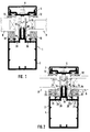
- the post 1 and the bar 2 each have in the illustrated embodiment identical profiles, namely both the main profiles 3, 4 and on these cover profiles 6 and 7 to be fastened by means of screws 5 are of identical design. Between the main profiles 1, 2 and the cover profiles 6, 7 are shown in the Exemplary embodiment insulating glass panes 8, 9 via seals 10. 11 and 12 held.
- Insulated profiles 15 and 16 pushed on by a curved crosspieces 17th form elastically expandable chamber 18 which is clamping and yet sliding slidably snaps over the connecting webs 13, 14.
- the side walls of the Chamber 18 are at the lower end with inward anchoring webs 19 provided which engage in corresponding grooves of the connecting webs.
- the insulating profile 16 for the connecting web 14 of the main profile 4 of the bolt 2 is provided with a contact wall 20 which on the webs 21 of the wall 22 of the Main profile 4 is slidably supported.
- the width of the contact wall 20 is slightly smaller than the width of the main profile 4, so that the seals 11 the outer counter-anchoring webs 23 can be designed to span. This gives the simple possibility that the seals 11 of the bolt in the view are as high or wide as the seals 10 of the posts.
- the side walls 24 of the insulating profile 16 forming the chamber 18 for the bolt form together with the system wall 20 and together with the counter anchor bars 23 the clamp for the seals 11 forming webs 25 - and the inner surfaces 26 of the seals 11 - the bolt-side drainage channels 27.
- These bolt-side drainage channels 27 open into the Drainage channels 28 of the posts 1.
- To accomplish this introduction must only be provided that the insulating profile 16, the locking profile 4 in the Exceeds length and in the post 3 to the drainage groove 28 of the post 3 is led. The previous notching of the bolts is therefore unnecessary.
- the chamber 18 In the region of the projection of the insulating profile 16 over the front end of the The main profile 4 of the bolt 2, the chamber 18 is open. To prevent that this point water can penetrate, a filler 29 is provided, which the chamber 18 fills in this protruding area. On the filler 29 are lateral Molded wings 30, 31, which engage in the groove 32 anchoring, the Main profile 3 of the post 1 serves to anchor the seals 10.
Landscapes
- Engineering & Computer Science (AREA)
- Architecture (AREA)
- Physics & Mathematics (AREA)
- Electromagnetism (AREA)
- Civil Engineering (AREA)
- Structural Engineering (AREA)
- Load-Bearing And Curtain Walls (AREA)
- Building Environments (AREA)
Abstract
Description
- Fig. 1
- einen Schnitt durch einen Pfosten,
- Fig. 2
- einen Schnitt durch einen Riegel,
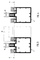
- Fig. 3 und 4
- Schnitte durch das Hauptprofil des Pfostens bzw. Riegels,
- Fig. 5
- einen Teilschnitt durch einen Pfosten und den angesetzten Riegel, wobei strichliert der Riegelquerschnitt noch mit eingezeichnet ist, und
- Fig. 6
- eine perspektivische Ansicht der Verbindung zwischen Pfosten und Riegel.
Claims (6)
- Gebäudefassade oder Dachfassade mit Ausfachungen, beispielsweise aus Isolierglasscheiben, bestehend aus einem Rahmenwerk aus Pfosten und Riegeln, wobei das Rahmenwerk an der Gebäudeseite sich aus Hauptprofilen und an der Außenseite, die Scheibenränder abdeckenden, mit den Hauptprofilen verschraubten oder eingehängten Deckprofilen zusammensetzt und die Hauptprofile mit randseitigen Verankerungsnuten zur Aufnahme von Dichtleisten ausgestattet sind und jeweils ineinander einmündende Entwässerungskanäle aufweisen, dadurch gekennzeichnet, daß die Anlageflächen der Hauptprofile (3, 4) der Pfosten (1) und Riegel (2) in einer Ebene (A) liegen und auf ihre mittigen Verbindungsstege (13, 14) Isolierprofile (15, 16) aufgesetzt sind, wobei das Isolierprofil (16) für den Riegel (2), das über dessen stirnseitiges Ende bis in den Entwässerungskanal (28) des Pfostens (1) einschiebbar ist, mit Entwässerungskanäle (27) bildenden Stegen (26) versehen ist, so daß die Entwässerungskanäle (27) des Riegels (2) in die Entwässerungskanäle (28) des Pfostens einmünden.
- Gebäudefassade nach Anspruch 1, dadurch gekennzeichnet, daß die Stege (25) Verankerungslängsstege für die Dichtungen (11) bilden.
- Gebäudefassade nach Anspruch 2, dadurch gekennzeichnet, daß die Anlagewand (20) des Isolierprofils (16) schmäler als das Hauptprofil (4) des Riegels ausgebildet ist und außen mit Gegenverankerungsstegen (23) für die die Gegenverankerungsstege (23) außen abdeckend übergreifenden Dichtungen (11) versehen ist.
- Gebäudefassade nach einem der Ansprüche 1 bis 3, dadurch gekennzeichnet, daß die den mittigen Verbindungssteg (14) aufnehmende, nach unten offene Kammer (18) des Isolierprofils (16) durch ein Füllstück (29) verschlossen ist.
- Gebäudefassade nach Anspruch 4, dadurch gekennzeichnet, daß am Füllstück (29) in eine Dichtungsaufnahmenut (32) des Hauptprofils (3) des Pfostens (1) eingreifende Seitenflügel (30, 31) angeformt sind.
- Gebäudefassade nach einem der Ansprüche 1 bis 5, dadurch gekennzeichnet, daß die Isolierprofile (15, 16) gewölbte oder gewinkelte, eine federnde Klemmaufweitung ermöglichende Querstege (17) aufweisen.
Applications Claiming Priority (2)
| Application Number | Priority Date | Filing Date | Title |
|---|---|---|---|
| DE19830087A DE19830087C2 (de) | 1998-07-06 | 1998-07-06 | Gebäudefassade oder Dachfassade mit einem Rahmenwerk aus Pfosten und Riegeln |
| DE19830087 | 1998-07-06 |
Publications (3)
| Publication Number | Publication Date |
|---|---|
| EP0971081A2 true EP0971081A2 (de) | 2000-01-12 |
| EP0971081A3 EP0971081A3 (de) | 2001-02-07 |
| EP0971081B1 EP0971081B1 (de) | 2002-10-23 |
Family
ID=7873093
Family Applications (1)
| Application Number | Title | Priority Date | Filing Date |
|---|---|---|---|
| EP99112699A Expired - Lifetime EP0971081B1 (de) | 1998-07-06 | 1999-07-02 | Gebäudefassade oder Dachfassade mit einem Rahmenwerk aus Pfosten und Riegeln |
Country Status (3)
| Country | Link |
|---|---|
| EP (1) | EP0971081B1 (de) |
| AT (1) | ATE226671T1 (de) |
| DE (2) | DE19830087C2 (de) |
Cited By (11)
| Publication number | Priority date | Publication date | Assignee | Title |
|---|---|---|---|---|
| WO2002029174A1 (de) * | 2000-09-30 | 2002-04-11 | SCHÜCO International KG | Im glasfalz einer fassade oder eines lichtdaches vorgesehene trägereinheit |
| EP1223257A1 (de) * | 2001-01-15 | 2002-07-17 | SCHÜCO International KG | Riegel/Pfosten-Konstruktion |
| DE10255223A1 (de) * | 2002-11-27 | 2004-06-17 | Wicona Bausysteme Gmbh | Gebäudefassade oder Dach |
| WO2006074973A1 (de) * | 2005-01-15 | 2006-07-20 | SCHÜCO International KG | Modulare fassade für gebäude, glasauflagedichtung und schraube |
| EP1577455A3 (de) * | 2004-03-18 | 2006-10-04 | Hermann Gutmann Werke AG | Gebäudefassade oder Dach mit Ausfachungen zur Aufnahme von Fassadenelementen |
| EP1860250A3 (de) * | 2006-05-26 | 2009-08-12 | Raico Bautechnik GmbH | Aufsatzdichtung |
| ES2351748A1 (es) * | 2008-10-07 | 2011-02-10 | Cerrajeria Gorris, S.L. | Dispositivo de montaje de fachadas ligeras. |
| EP1580342A3 (de) * | 2004-03-24 | 2012-03-07 | Norsk Hydro Asa | Pfostenprofils für eine aus Pfosten und Riegeln in Form von Hohlprofilen bestehende Rahmenkonstruktion |
| AT511685A1 (de) * | 2011-06-16 | 2013-01-15 | Alutechnik Matauschek Gmbh | Pfosten-riegel-system |
| EP2116659A3 (de) * | 2008-05-07 | 2013-02-27 | Gutmann Ag | Gebäudefassade oder Dachfassade mit Ausfachung |
| EP1754841B1 (de) * | 2005-08-17 | 2013-12-18 | Raico Bautechnik GmbH | Isolatorprofil |
Families Citing this family (4)
| Publication number | Priority date | Publication date | Assignee | Title |
|---|---|---|---|---|
| DE10200449B4 (de) | 2002-01-09 | 2006-03-09 | Eduard Hueck Gmbh & Co Kg | Pfosten-/Riegel-Konstruktion, insbesondere für Fassaden, Dächer und dergleichen |
| DE10347698A1 (de) * | 2003-10-14 | 2005-06-09 | Unilux Ag | Gebäudefassade mit Fenster |
| DE202007004060U1 (de) | 2007-03-15 | 2007-05-24 | Sälzer Sicherheitstechnik GmbH | Gebäudeabschluss in sprengwirkungshemmender Ausführung |
| DE102022117776B3 (de) | 2022-07-15 | 2023-10-12 | HUECK System GmbH & Co. KG | Dichtungselement mit entwässerungsmittel |
Citations (2)
| Publication number | Priority date | Publication date | Assignee | Title |
|---|---|---|---|---|
| DE3419538C2 (de) | 1984-05-25 | 1989-02-23 | Schueco Heinz Schuermann Gmbh & Co, 4800 Bielefeld, De | |
| DE19516778A1 (de) | 1995-01-07 | 1996-07-18 | Wicona Bausysteme Gmbh | Gebäudefassade oder Dach |
Family Cites Families (9)
| Publication number | Priority date | Publication date | Assignee | Title |
|---|---|---|---|---|
| DE8901978U1 (de) * | 1989-02-20 | 1989-06-29 | Proksch, Kurt, 7206 Emmingen-Liptingen | Bausatz zum Erstellen einer Rahmenkonstruktion, insbesondere für den Glas- oder Fassadenbau |
| GB8911805D0 (en) * | 1989-05-23 | 1989-07-12 | H H Robertson Uk Limited | Improvements in and relating to curtain walls |
| DE4000769A1 (de) * | 1990-01-12 | 1991-07-18 | Reynolds Aluminium Deutschland | Traggerippe fuer eine oder an einer fassadenwand |
| DE4210575A1 (de) * | 1992-03-31 | 1993-10-07 | Herbert Lacker | Unterkonstruktion für Glasdächer und Glasfassaden |
| DE4432568C2 (de) * | 1994-04-11 | 1997-09-04 | Gerhard Kaese | Vorrichtung zur Befestigung von Platten an Fassaden |
| DE19521920C2 (de) * | 1995-06-09 | 1997-05-15 | Mannesmann Ag | Befestigungselement für ein Fassadensystem |
| DE29516734U1 (de) * | 1995-10-24 | 1995-12-14 | Syntax Rackwitz Systemtechnik GmbH, 04519 Rackwitz | Einspannrahmen |
| DE29607770U1 (de) * | 1996-04-29 | 1996-07-18 | Kaese, Gerhard, 31840 Hessisch Oldendorf | Drei-Kammer-System mit einer integrierten Mitteldichtung an Pfosten-/Riegelfassaden |
| DE29613579U1 (de) * | 1996-08-06 | 1996-09-19 | Fa. J. Eberspächer, 73730 Esslingen | Dichtungsanordnung für einen Holm, insbesondere aus Aluminium, als Trägerteil einer Fassaden- oder Dachkonstruktion |
-
1998
- 1998-07-06 DE DE19830087A patent/DE19830087C2/de not_active Expired - Fee Related
-
1999
- 1999-07-02 AT AT99112699T patent/ATE226671T1/de active
- 1999-07-02 DE DE59903147T patent/DE59903147D1/de not_active Expired - Lifetime
- 1999-07-02 EP EP99112699A patent/EP0971081B1/de not_active Expired - Lifetime
Patent Citations (2)
| Publication number | Priority date | Publication date | Assignee | Title |
|---|---|---|---|---|
| DE3419538C2 (de) | 1984-05-25 | 1989-02-23 | Schueco Heinz Schuermann Gmbh & Co, 4800 Bielefeld, De | |
| DE19516778A1 (de) | 1995-01-07 | 1996-07-18 | Wicona Bausysteme Gmbh | Gebäudefassade oder Dach |
Cited By (14)
| Publication number | Priority date | Publication date | Assignee | Title |
|---|---|---|---|---|
| HRP20030236B1 (hr) * | 2000-09-30 | 2011-12-31 | Sch�Co International Kg | Jedinica za nošenje predviđena za ostakljivanje fasade ili prozirnog krova |
| CZ304423B6 (cs) * | 2000-09-30 | 2014-04-30 | SCHĂśCO INTERNATIONAL KG | Fasáda nebo světlík s kostrou ze sloupkových profilů a příčlových profilů a s výplněmi |
| WO2002029174A1 (de) * | 2000-09-30 | 2002-04-11 | SCHÜCO International KG | Im glasfalz einer fassade oder eines lichtdaches vorgesehene trägereinheit |
| EP1223257A1 (de) * | 2001-01-15 | 2002-07-17 | SCHÜCO International KG | Riegel/Pfosten-Konstruktion |
| DE10255223A1 (de) * | 2002-11-27 | 2004-06-17 | Wicona Bausysteme Gmbh | Gebäudefassade oder Dach |
| EP1426516A3 (de) * | 2002-11-27 | 2006-02-01 | Norsk Hydro Asa | Gebäudefassade oder Dach |
| EP1577455A3 (de) * | 2004-03-18 | 2006-10-04 | Hermann Gutmann Werke AG | Gebäudefassade oder Dach mit Ausfachungen zur Aufnahme von Fassadenelementen |
| EP1580342A3 (de) * | 2004-03-24 | 2012-03-07 | Norsk Hydro Asa | Pfostenprofils für eine aus Pfosten und Riegeln in Form von Hohlprofilen bestehende Rahmenkonstruktion |
| WO2006074973A1 (de) * | 2005-01-15 | 2006-07-20 | SCHÜCO International KG | Modulare fassade für gebäude, glasauflagedichtung und schraube |
| EP1754841B1 (de) * | 2005-08-17 | 2013-12-18 | Raico Bautechnik GmbH | Isolatorprofil |
| EP1860250A3 (de) * | 2006-05-26 | 2009-08-12 | Raico Bautechnik GmbH | Aufsatzdichtung |
| EP2116659A3 (de) * | 2008-05-07 | 2013-02-27 | Gutmann Ag | Gebäudefassade oder Dachfassade mit Ausfachung |
| ES2351748A1 (es) * | 2008-10-07 | 2011-02-10 | Cerrajeria Gorris, S.L. | Dispositivo de montaje de fachadas ligeras. |
| AT511685A1 (de) * | 2011-06-16 | 2013-01-15 | Alutechnik Matauschek Gmbh | Pfosten-riegel-system |
Also Published As
| Publication number | Publication date |
|---|---|
| DE19830087A1 (de) | 2000-01-27 |
| EP0971081B1 (de) | 2002-10-23 |
| DE19830087C2 (de) | 2000-09-14 |
| EP0971081A3 (de) | 2001-02-07 |
| DE59903147D1 (de) | 2002-11-28 |
| ATE226671T1 (de) | 2002-11-15 |
Similar Documents
| Publication | Publication Date | Title |
|---|---|---|
| DE19830087C2 (de) | Gebäudefassade oder Dachfassade mit einem Rahmenwerk aus Pfosten und Riegeln | |
| DE20100747U1 (de) | Riegel/Pfosten-Konstruktion | |
| DE3621408C2 (de) | ||
| DE202014010902U1 (de) | Isolierelement für Fassaden- oder Lichtdachkonstruktionen | |
| DE10223038B4 (de) | Fassadenkonstruktion mit einem durch ein Dichtelement abgedichteten riegelseitigen Isolierprofil | |
| CH677252A5 (de) | ||
| EP0569654A1 (de) | Alu-Holz-Verbundprofil für die Herstellung von Fenstern, daraus hergestelltes Fenster und Verfahren zur Herstellung eines solchen Fensters | |
| AT392311B (de) | Rahmenkonstruktion in pfosten-riegel-bauweise, insbesondere fuer fassaden, daecher, fensterwaende od. dgl. | |
| DE202008004373U1 (de) | Elementierte Pfosten-Riegel-Fassade | |
| DE10035772A1 (de) | Aufsatzdichtung für eine Pfosten-/Riegel-Konstruktion | |
| DE10200449A1 (de) | Pfosten-/Riegel-Konstruktion, insbesondere für Fassaden, Dächer und dergleichen | |
| DE19544077C2 (de) | Gegen Hitzeeinwirkung widerstandsfähige Verglasung | |
| DE9107171U1 (de) | Pfosten- und Riegelprofilgerüst für eine mit Flächenelementen ausgefachte Wand- oder Deckenkonstruktion | |
| EP1020576A2 (de) | Fassade oder Lichtdach mit einem Rahmenwerk aus Pfosten- und Sprossenprofilen | |
| EP3211147B1 (de) | Pfosten-riegel-konstruktion | |
| EP1327035B1 (de) | Trägereinheit im Glasfalz einer Fassade oder eines Lichtdaches | |
| DE3510742A1 (de) | Haltevorrichtung fuer eine glaswand bildende verglasungen | |
| DE202004006987U1 (de) | Andruckleiste für eine Gebäudefassade oder ein Dach | |
| DE3211427A1 (de) | Profilleiste | |
| DE8716012U1 (de) | Rahmenkonstruktion in Pfosten-Riegel-Bauweise, insbesondere für Fassaden, Dächer, Fensterwände od. dgl. | |
| DE19736860C2 (de) | Wärmegedämmte Fassade mit Fensterbändern | |
| DE3604101A1 (de) | Metallprofile fuer wintergartenkonstruktionen | |
| EP3907340B1 (de) | Dichtungsprofil und pfosten-riegel-konstruktion | |
| DE2903463C2 (de) | Abdichtung zwischen einem Fassadenpfosten oder dergleichen und einem an diesem Pfosten anschlagenden Tür- oder Fensterflügel | |
| DE3830397A1 (de) | Rahmenkonstruktion in pfosten-riegel-bauweise, insbesondere fuer fassaden, daecher od. dgl. |
Legal Events
| Date | Code | Title | Description |
|---|---|---|---|
| PUAI | Public reference made under article 153(3) epc to a published international application that has entered the european phase |
Free format text: ORIGINAL CODE: 0009012 |
|
| AK | Designated contracting states |
Kind code of ref document: A2 Designated state(s): AT BE CH CY DE DK ES FI FR GB GR IE IT LI LU MC NL PT SE |
|
| AX | Request for extension of the european patent |
Free format text: AL;LT;LV;MK;RO;SI |
|
| 17P | Request for examination filed |
Effective date: 20001020 |
|
| PUAL | Search report despatched |
Free format text: ORIGINAL CODE: 0009013 |
|
| AK | Designated contracting states |
Kind code of ref document: A3 Designated state(s): AT BE CH CY DE DK ES FI FR GB GR IE IT LI LU MC NL PT SE |
|
| AX | Request for extension of the european patent |
Free format text: AL;LT;LV;MK;RO;SI |
|
| 17Q | First examination report despatched |
Effective date: 20010131 |
|
| GRAG | Despatch of communication of intention to grant |
Free format text: ORIGINAL CODE: EPIDOS AGRA |
|
| AKX | Designation fees paid |
Free format text: AT BE CH CY DE DK ES FI FR GB GR IE IT LI LU MC NL PT SE |
|
| GRAG | Despatch of communication of intention to grant |
Free format text: ORIGINAL CODE: EPIDOS AGRA |
|
| GRAH | Despatch of communication of intention to grant a patent |
Free format text: ORIGINAL CODE: EPIDOS IGRA |
|
| GRAH | Despatch of communication of intention to grant a patent |
Free format text: ORIGINAL CODE: EPIDOS IGRA |
|
| GRAA | (expected) grant |
Free format text: ORIGINAL CODE: 0009210 |
|
| AK | Designated contracting states |
Kind code of ref document: B1 Designated state(s): AT BE CH CY DE DK ES FI FR GB GR IE IT LI LU MC NL PT SE |
|
| PG25 | Lapsed in a contracting state [announced via postgrant information from national office to epo] |
Ref country code: IT Free format text: LAPSE BECAUSE OF FAILURE TO SUBMIT A TRANSLATION OF THE DESCRIPTION OR TO PAY THE FEE WITHIN THE PRESCRIBED TIME-LIMIT;WARNING: LAPSES OF ITALIAN PATENTS WITH EFFECTIVE DATE BEFORE 2007 MAY HAVE OCCURRED AT ANY TIME BEFORE 2007. THE CORRECT EFFECTIVE DATE MAY BE DIFFERENT FROM THE ONE RECORDED. Effective date: 20021023 Ref country code: IE Free format text: LAPSE BECAUSE OF FAILURE TO SUBMIT A TRANSLATION OF THE DESCRIPTION OR TO PAY THE FEE WITHIN THE PRESCRIBED TIME-LIMIT Effective date: 20021023 Ref country code: GR Free format text: LAPSE BECAUSE OF FAILURE TO SUBMIT A TRANSLATION OF THE DESCRIPTION OR TO PAY THE FEE WITHIN THE PRESCRIBED TIME-LIMIT Effective date: 20021023 Ref country code: GB Free format text: LAPSE BECAUSE OF FAILURE TO SUBMIT A TRANSLATION OF THE DESCRIPTION OR TO PAY THE FEE WITHIN THE PRESCRIBED TIME-LIMIT Effective date: 20021023 Ref country code: FI Free format text: LAPSE BECAUSE OF FAILURE TO SUBMIT A TRANSLATION OF THE DESCRIPTION OR TO PAY THE FEE WITHIN THE PRESCRIBED TIME-LIMIT Effective date: 20021023 |
|
| REF | Corresponds to: |
Ref document number: 226671 Country of ref document: AT Date of ref document: 20021115 Kind code of ref document: T |
|
| REG | Reference to a national code |
Ref country code: GB Ref legal event code: FG4D Free format text: NOT ENGLISH |
|
| REG | Reference to a national code |
Ref country code: CH Ref legal event code: EP |
|
| REG | Reference to a national code |
Ref country code: IE Ref legal event code: FG4D Free format text: GERMAN |
|
| REF | Corresponds to: |
Ref document number: 59903147 Country of ref document: DE Date of ref document: 20021128 |
|
| PG25 | Lapsed in a contracting state [announced via postgrant information from national office to epo] |
Ref country code: SE Free format text: LAPSE BECAUSE OF FAILURE TO SUBMIT A TRANSLATION OF THE DESCRIPTION OR TO PAY THE FEE WITHIN THE PRESCRIBED TIME-LIMIT Effective date: 20030123 Ref country code: PT Free format text: LAPSE BECAUSE OF FAILURE TO SUBMIT A TRANSLATION OF THE DESCRIPTION OR TO PAY THE FEE WITHIN THE PRESCRIBED TIME-LIMIT Effective date: 20030123 Ref country code: DK Free format text: LAPSE BECAUSE OF FAILURE TO SUBMIT A TRANSLATION OF THE DESCRIPTION OR TO PAY THE FEE WITHIN THE PRESCRIBED TIME-LIMIT Effective date: 20030123 |
|
| RAP2 | Party data changed (patent owner data changed or rights of a patent transferred) |
Owner name: THYSSEN SCHULTE GUTMANN BAUSYSTEME GMBH |
|
| GBV | Gb: ep patent (uk) treated as always having been void in accordance with gb section 77(7)/1977 [no translation filed] |
Effective date: 20021023 |
|
| PG25 | Lapsed in a contracting state [announced via postgrant information from national office to epo] |
Ref country code: ES Free format text: LAPSE BECAUSE OF FAILURE TO SUBMIT A TRANSLATION OF THE DESCRIPTION OR TO PAY THE FEE WITHIN THE PRESCRIBED TIME-LIMIT Effective date: 20030429 |
|
| ET | Fr: translation filed | ||
| NLS | Nl: assignments of ep-patents |
Owner name: THYSSEN SCHULTE GUTMANN BAUSYSTEME GMBH |
|
| PG25 | Lapsed in a contracting state [announced via postgrant information from national office to epo] |
Ref country code: LU Free format text: LAPSE BECAUSE OF NON-PAYMENT OF DUE FEES Effective date: 20030702 Ref country code: CY Free format text: LAPSE BECAUSE OF FAILURE TO SUBMIT A TRANSLATION OF THE DESCRIPTION OR TO PAY THE FEE WITHIN THE PRESCRIBED TIME-LIMIT Effective date: 20030702 |
|
| PGFP | Annual fee paid to national office [announced via postgrant information from national office to epo] |
Ref country code: NL Payment date: 20030721 Year of fee payment: 5 Ref country code: FR Payment date: 20030721 Year of fee payment: 5 |
|
| PG25 | Lapsed in a contracting state [announced via postgrant information from national office to epo] |
Ref country code: MC Free format text: LAPSE BECAUSE OF NON-PAYMENT OF DUE FEES Effective date: 20030731 Ref country code: BE Free format text: LAPSE BECAUSE OF NON-PAYMENT OF DUE FEES Effective date: 20030731 |
|
| REG | Reference to a national code |
Ref country code: IE Ref legal event code: FD4D Ref document number: 0971081E Country of ref document: IE |
|
| PLBE | No opposition filed within time limit |
Free format text: ORIGINAL CODE: 0009261 |
|
| STAA | Information on the status of an ep patent application or granted ep patent |
Free format text: STATUS: NO OPPOSITION FILED WITHIN TIME LIMIT |
|
| 26N | No opposition filed |
Effective date: 20030724 |
|
| BERE | Be: lapsed |
Owner name: *HERMANN GUTMANN WERKE G.M.B.H. Effective date: 20030731 |
|
| PG25 | Lapsed in a contracting state [announced via postgrant information from national office to epo] |
Ref country code: NL Free format text: LAPSE BECAUSE OF NON-PAYMENT OF DUE FEES Effective date: 20050201 |
|
| PG25 | Lapsed in a contracting state [announced via postgrant information from national office to epo] |
Ref country code: FR Free format text: LAPSE BECAUSE OF NON-PAYMENT OF DUE FEES Effective date: 20050331 |
|
| NLV4 | Nl: lapsed or anulled due to non-payment of the annual fee |
Effective date: 20050201 |
|
| REG | Reference to a national code |
Ref country code: FR Ref legal event code: ST |
|
| REG | Reference to a national code |
Ref country code: CH Ref legal event code: PUE Owner name: THYSSEN SCHULTE GUTMANN BAUSYSTEME GMBH Free format text: HERMANN GUTMANN WERKE GMBH#NUERNBERGER STRASSE 57-81#91781 WEISSENBURG (DE) -TRANSFER TO- THYSSEN SCHULTE GUTMANN BAUSYSTEME GMBH#DREHBRUECKENSTRASSE 5-11#44147 DORTMUND (DE) Ref country code: CH Ref legal event code: PFA Owner name: HERMANN GUTMANN WERKE AG Free format text: THYSSEN SCHULTE GUTMANN BAUSYSTEME GMBH#DREHBRUECKENSTRASSE 5-11#44147 DORTMUND (DE) -TRANSFER TO- HERMANN GUTMANN WERKE AG#NUERNBERGER STRASSE 57-81#91781 WEISSENBURG (DE) Ref country code: CH Ref legal event code: NV Representative=s name: PATENTANWAELTE SCHAAD, BALASS, MENZL & PARTNER AG |
|
| REG | Reference to a national code |
Ref country code: CH Ref legal event code: PFA Owner name: GUTMANN AG Free format text: HERMANN GUTMANN WERKE AG#NUERNBERGER STRASSE 57-81#91781 WEISSENBURG (DE) -TRANSFER TO- GUTMANN AG#NUERNBERGER STRASSE 57#91781 WEISSENBURG (DE) |
|
| REG | Reference to a national code |
Ref country code: DE Ref legal event code: R081 Ref document number: 59903147 Country of ref document: DE Owner name: GUTMANN AG, DE Free format text: FORMER OWNER: HERMANN GUTMANN WERKE AG, 91781 WEISSENBURG, DE Effective date: 20110311 |
|
| PGFP | Annual fee paid to national office [announced via postgrant information from national office to epo] |
Ref country code: CH Payment date: 20110725 Year of fee payment: 13 |
|
| PGFP | Annual fee paid to national office [announced via postgrant information from national office to epo] |
Ref country code: AT Payment date: 20110720 Year of fee payment: 13 |
|
| REG | Reference to a national code |
Ref country code: AT Ref legal event code: MM01 Ref document number: 226671 Country of ref document: AT Kind code of ref document: T Effective date: 20120702 |
|
| PG25 | Lapsed in a contracting state [announced via postgrant information from national office to epo] |
Ref country code: AT Free format text: LAPSE BECAUSE OF NON-PAYMENT OF DUE FEES Effective date: 20120702 |
|
| REG | Reference to a national code |
Ref country code: CH Ref legal event code: PL |
|
| PG25 | Lapsed in a contracting state [announced via postgrant information from national office to epo] |
Ref country code: LI Free format text: LAPSE BECAUSE OF NON-PAYMENT OF DUE FEES Effective date: 20130731 Ref country code: CH Free format text: LAPSE BECAUSE OF NON-PAYMENT OF DUE FEES Effective date: 20130731 |
|
| REG | Reference to a national code |
Ref country code: DE Ref legal event code: R409 Ref document number: 59903147 Country of ref document: DE Ref country code: DE Ref legal event code: R119 Ref document number: 59903147 Country of ref document: DE |
|
| REG | Reference to a national code |
Ref country code: DE Ref legal event code: R409 Ref document number: 59903147 Country of ref document: DE |
|
| PGFP | Annual fee paid to national office [announced via postgrant information from national office to epo] |
Ref country code: DE Payment date: 20170711 Year of fee payment: 19 |
|
| REG | Reference to a national code |
Ref country code: DE Ref legal event code: R119 Ref document number: 59903147 Country of ref document: DE |
|
| PG25 | Lapsed in a contracting state [announced via postgrant information from national office to epo] |
Ref country code: DE Free format text: LAPSE BECAUSE OF NON-PAYMENT OF DUE FEES Effective date: 20190201 |