EP0970511B1 - Procede et dispositif permettant de chasser un liquide d'une surface - Google Patents
Procede et dispositif permettant de chasser un liquide d'une surface Download PDFInfo
- Publication number
- EP0970511B1 EP0970511B1 EP98944906A EP98944906A EP0970511B1 EP 0970511 B1 EP0970511 B1 EP 0970511B1 EP 98944906 A EP98944906 A EP 98944906A EP 98944906 A EP98944906 A EP 98944906A EP 0970511 B1 EP0970511 B1 EP 0970511B1
- Authority
- EP
- European Patent Office
- Prior art keywords
- liquid
- substrate
- recited
- supply system
- centre
- Prior art date
- Legal status (The legal status is an assumption and is not a legal conclusion. Google has not performed a legal analysis and makes no representation as to the accuracy of the status listed.)
- Expired - Lifetime
Links
Images


Classifications
-
- H—ELECTRICITY
- H01—ELECTRIC ELEMENTS
- H01L—SEMICONDUCTOR DEVICES NOT COVERED BY CLASS H10
- H01L21/00—Processes or apparatus adapted for the manufacture or treatment of semiconductor or solid state devices or of parts thereof
- H01L21/67—Apparatus specially adapted for handling semiconductor or electric solid state devices during manufacture or treatment thereof; Apparatus specially adapted for handling wafers during manufacture or treatment of semiconductor or electric solid state devices or components ; Apparatus not specifically provided for elsewhere
- H01L21/67005—Apparatus not specifically provided for elsewhere
- H01L21/67011—Apparatus for manufacture or treatment
- H01L21/67017—Apparatus for fluid treatment
- H01L21/67028—Apparatus for fluid treatment for cleaning followed by drying, rinsing, stripping, blasting or the like
- H01L21/67034—Apparatus for fluid treatment for cleaning followed by drying, rinsing, stripping, blasting or the like for drying
-
- H—ELECTRICITY
- H01—ELECTRIC ELEMENTS
- H01L—SEMICONDUCTOR DEVICES NOT COVERED BY CLASS H10
- H01L21/00—Processes or apparatus adapted for the manufacture or treatment of semiconductor or solid state devices or of parts thereof
- H01L21/67—Apparatus specially adapted for handling semiconductor or electric solid state devices during manufacture or treatment thereof; Apparatus specially adapted for handling wafers during manufacture or treatment of semiconductor or electric solid state devices or components ; Apparatus not specifically provided for elsewhere
- H01L21/67005—Apparatus not specifically provided for elsewhere
- H01L21/67011—Apparatus for manufacture or treatment
- H01L21/67017—Apparatus for fluid treatment
- H01L21/67028—Apparatus for fluid treatment for cleaning followed by drying, rinsing, stripping, blasting or the like
Definitions
- the present invention is related to a method of removing a liquid from a rotating substrate.
- This liquid can be any wet processing liquid as e.g. a wet etching liquid or a cleaning liquid. It can also be a rinsing liquid.
- the invention is applicable for a number of wet processing steps which are frequently used in the fabrication process of integrated circuits or liquid crystal displays.
- the complete and efficient removal of a liquid from a surface of a substrate is a multiply repeated step in e.g. the fabrication process of integrated circuits. Such a step can be performed after a wet etching step or a wet cleaning step or a wet rinsing step or any other step used in said fabrication process wherein said substrate is treated or exposed or immersed in a liquid.
- Said substrate can be a semiconductor wafer or a part thereof or a glass slice or any other slice of an insulating or conductive material.
- one of the major challenges regarding single wafer wet processing is a method for removing a liquid from both sides of a substrate.
- the method should work sufficiently fast. Knowing that in state of the art production lines a substrate is processed typically every 2 to 3 minutes, ideally, in order to avoid equipment duplication, the process step and the liquid removal step should be completed in about such a time frame. Another requirement is related to the preferred substrate orientation. State of the art processing equipment and transportation tools are developed to handle substrates in a horizontal position. Therefore in order to avoid additional substrate handling it would be desirable to perform the wet processing steps using horizontally positioned substrates.
- the Japanese Patent Abstract JP-07211686 discloses a process to dry a substrate such as a wafer on the two opposite sides.
- a wafer is cleaned in a cleaning tank and further rinsed in a rinsing/ drying tank.
- pure water is sprayed on the upper surface of the substrate such that the final rinse is performed.
- the wafer is rotated and subsequently high temperature IPA vapour is delivered in the tank (on the opposite side of the substrate) while spin drying is sustained. During this stage, no extra liquid is supplied on any other side of the wafer.
- Document WO-A-9610463 is related to a method and apparatus for cleaning surfaces of a substrate.
- it is described how water is fed onto the surface of the substrate through a lance, and how steam is sprayed directly into the water film which forms on the surface. Vapour bubbles then form in the water film, which either immediately collapse again or burst at the surface of the water film. The pulsing action of the steam helps to remove particles from the surface, thereby cleaning it.
- a method is disclosed of removing a liquid from at least one surface of at least one substrate comprising the steps of:
- said rotary movement is performed at a speed to guide said liquid-ambient boundary over said substrate.
- this speed can be between 2 and 40 revolutions per second or between 1 and 50 revolutions per second or more than 40 revolutions per second.
- this boundary is a curved boundary.
- the configuration is such that the liquid is kept at the outerside of the curved boundary, i.e. at the liquid side of the liquid-ambient boundary. No liquid is present at the ambient side of the liquid-ambient boundary.
- the substrate can rotate around its own axis.
- said substrate can also be subjected to a rotary movement where said substrate no longer rotates around its own centre but around an axis parallel to and offset to the axis perpendicular to and through the centre of the substrate.
- fresh liquid is sprayed continuously.
- the entire surface at the liquid side of the liquid-ambient boundary can be covered, as e.g. for hydrophilic surfaces, with a continuous film of the liquid.
- the speed of the rotary movement is chosen such that the flow of said sprayed liquid on at least one side of the wafer is transported outwards due to the centrifugal forces.
- the resulting surface tension reduction of said liquid facilitates the movement of said liquid towards an edge of the substrate.
- the surface left behind is cleaned and dried. It is presumed that this drying action is obtained according to at least the combination of the rotary movement and the Marangoni effect.
- the Marangoni effect by locally heating the liquid a temperature gradient will be created in the liquid meniscus. This temperature gradient creates an additional force exerted on the liquid film in the direction of the liquid film resulting in a good drying performance.
- the liquid is selected dependent upon the applied wet processing step like e.g. a wet etching step or a cleaning step or a rinsing step.
- the liquid is locally heated by a heat source to reduce the surface tension of the liquid.
- the heat source can be a nozzle, movable or not, or a static inlet dispensing a heated gas or a heated vapor or a heated mixture of a vapor and a gas.
- other heat sources can be used such as laser beams or other energetic beams, provided that they can be sufficiently localized.
- a vapor is defined as the gas phase occurrence of an element or of a compound or of a mixture of elements if the element or compound or mixture should be in the liquid or solid phase at the given temperature and pressure conditions. Thus a vapor can co-exist in one environment with the solid or liquid phase of the element.
- a vapor is a specific gas phase occurrence of an element or a compound or a mixture of elements.
- another force can be combined with the liquid removal process of the present invention.
- sonic energy as said other force to agitate the liquid applied during the removal process the cleaning performance of said liquid removal process can be enhanced. Doing so can help in particle reduction.
- contacting a surface with a rotating cleaning pad is an example of such other force.
- a cleaning or a rinsing liquid or a sequence of such liquids can be supplied to the entire surface of a rotating substrate.
- the parameters can be optimized such that a liquid film can completely cover a surface.
- the spinning motion will quickly transport the liquid over the surface towards the edge, thus allowing relatively short carry-over transients and thus also allowing for relatively short rinsing times.
- Using such a continuously switched flow of liquids eliminates the undesirable passage of liquid-gas interfaces over the surface.
- the liquid removal method of the present invention is applicable for each sequence of at least one wet processing step by the liquid in order to reduce the surface tension of the liquid.
- the drying can thus be applied directly on the processing liquid if relevant for the application. Since the proposed drying technique is found to be very fast, process non-uniformity over the surface can be kept very low.
- an apparatus as defined in claim 13 for removing a liquid from at least one surface of at least one substrate, said apparatus comprising:
- said apparatus further comprises a chamber, wherein said substrate holder is positioned.
- This chamber is designed in a manner to avoid back splashing of the liquid removed from a surface onto said surface.
- a chamber having slanted walls may be used.
- said apparatus further comprises a generator of mechanical vibrations and a transmitter for transmitting said vibrational energy to a surface of the substrate via the liquid being supplied at said surface.
- the heat source is at least one nozzle which dispenses a heated gas or a heated vapor or a heated mixture of a vapor and a gas on said surface of said substrate and said liquid supply system can comprise at least one nozzle for applying said liquid on said surface of said substrate, said nozzles are positioned such that the position where the heating is performed is closer to the centre of the rotary movement of the substrate holder than the position where the liquid is applied.
- a sharply defined liquid-ambient boundary can be created which is located inbetween a first and a second adjacent nozzle, said first nozzle being part of said heat source, said second nozzle being part of said liquid supply system.
- said nozzles can be mounted on an arm, said nozzles being movable on said arm and/or said arm being movable relative to said substrate.
- the heat source can also be a laser beam or another energetic beam instead of a gas nozzle.
- the temperature of this heated gas or this heated vapor or this heated mixture is typically in the range from 20 to 200 degrees Celsius. However, the temperature of this heated gas or this heated vapor or this heated mixture is always higher than the temperature of the liquid.
- a method of removing a liquid from at least one surface of at least one substrate comprising the steps of:
- fresh liquid is dispensed continuously.
- the entire surface at the liquid side of the liquid-ambient boundary can be covered with a film of the liquid.
- the speed of the rotary movement is chosen such that the flow of said liquid dispensed on said surface of the wafer is transported outwards due to the centrifugal forces.
- the rotational speed, the flow of the liquid supply, and the orientation and the velocity at which the liquid arrives on the surface can be optimized in order to result in a liquid film with a sharp and stable liquid-ambient boundary and to keep the thickness of the liquid film small enough to avoid excessive losses of liquid particularly on the bottomside by gravitational forces.
- this drying action is obtained according to at least the combination of the Marangoni effect and a second force.
- this second force is the force introduced by a rotary movement or e.g. an oscillating movement.
- the Marangoni effect by locally heating the liquid a temperature gradient will be created in the liquid meniscus. This temperature gradient creates an additional force exerted on the liquid film in the direction of the liquid film resulting in a good drying performance.
- the centre of the rotary movement can coincide with the centre of the substrate, i.e.
- a curved shaped liquid-ambient boundary is created.
- the entire surface area outside of this curved boundary can be covered with a film of the liquid.
- the entire surface area outside of this curved boundary is covered with a continuous film of the liquid.
- other more complex shaped boundaries can be created, particularly on substrates with a high contact angle for the liquid and if a low flow of liquid is applied. Such complex shaped boundaries will also assist in removing a liquid.
- the liquid is selected dependent on the applied wet processing step: for etching steps, e.g. dilute aqueous solutions comprising e.g. HF can be used; for cleaning steps, e.g. a mixture of NH 4 OH, H 2 O 2 and H 2 O or a mixture of HCl, H 2 O 2 and H 2 O or dilute HCl or a mixture comprising O 3 can be used; for rinsing steps, the rinsing liquid can comprise H 2 O, or a mixture of H 2 O and an acid, said mixture preferably having a pH between 2 and 6.
- said acid is one of the group of HNO 3 , H 2 CO 3 , HCO 3 , HCl, HBr, H 3 PO 4 , H 2 SO 4 .
- the liquid is dispensed on least a part of at least one surface of said substrate and said liquid is locally heated by a heat source.
- the heat source can be a nozzle, movable or not, or a static inlet dispensing a heated gas or a heated vapor or a heated mixture of a vapor and a gas.
- other heat sources can be used such as laser beams or other energetic beams, provided that they can be sufficiently localized.
- the implementation has to be such that initially the heating is performed locally at or very close to the centre of the rotary movement, while the liquid is supplied slightly out of centre but adjacent to the position where the heating is performed.
- the liquid can also be supplied further away from said centre.
- a liquid-ambient boundary can be formed which is initially located at said centre. Then, due to the rotary movement and the movement of the heating source and the liquid supply system, this boundary is slowly guided outwards from the centre to the edge to thereby remove the liquid or the solution of said liquid from said surface of said substrate.
- a sharply defined liquid-ambient boundary, at least locally, is helpful in order to obtain an optimal performance.
- the method of the present invention is perfectly suited to handle a horizontal positioned substrate resulting in a secure and reliable approach which is compatible with substrate handling in most of the other process steps in the manufacturing of integrated circuits.
- the liquid of the liquid-ambient boundary is continuously refreshed, besides a good drying performance also a better cleaning performance is obtained simultaneously.
- a better cleaning performance can be obtained regardless of the precise nature of the liquid, i.e. a wet processing liquid like e.g. a cleaning liquid or a rinsing liquid or a wet etching liquid, as long as the liquid is compatible with the applied heating.
- the required amounts of liquid are substantially lower compared with conventional wet processing baths or tanks.
- the liquid can be supplied on a surface of a substrate at or very close to the centre of the rotary movement, while there is no gaseous substance supply. Then, the liquid supply is moved to supply the liquid slightly out of said centre and the liquid is locally heated at said centre while supplying liquid.
- the liquid can be supplied on a surface of a substrate at or very close to the centre of the rotary movement, while substantially simultaneously a the heat source is turned on to thereby locally heat the liquid adjacent to the centre of the rotary movement.
- This heat source can be positioned adjacent to said liquid supply. Then, the liquid supply is moved slightly out of said centre, while the heat source is moved to supply heat to the liquid at said centre said centre.
- the ambient is a gas, preferably air and more preferably dry air.
- the centre of the rotary movement coincides with the centre of the substrate, i.e. the substrate rotates around its own centre.
- the heating source is moved to the centre of the rotary movement, i.e. the centre of the substrate, and the heating source is activated to locally heat the liquid at said centre while the liquid is supplied slightly out of centre. Additional liquid can also be supplied further away from said centre.
- a liquid-ambient boundary is formed which is initially located at said centre. Then, due to the rotary movement and the movement of the heat source and the liquid supply system, this boundary is slowly guided outwards from the centre to the edge of said surface of said substrate to thereby remove the liquid or the solution of said liquid from said surface of said substrate.
- the method of the present invention is applied on the removal of liquid from hydrophilic silicon wafers with a diameter of 150 mm.
- the removal of the liquid from one surface, being the top side, of the wafer was evaluated.
- the wafer was mounted on a rotating vacuum chuck.
- the wafer was rotating around its centre at a speed of approximately 300 rpm.
- N 2 gas was heated using a simple heater equipped with a thermocouple-thermometer. Because of hardware limitations the maximum temperature of the gas that could be reached was approximately 50°C. In the tests this maximum temperature was chosen.
- the N 2 flow was set to approximately 3 slm.
- the liquid was ultra pure water and was supplied through a nozzle at a flow of approximately 70 ml/min.
- the hot N2 flow was applied through a second nozzle that was mounted on the same gear moving at a velocity of approximately 0.8 mm/s from the centre of the wafer to the edge. Using these non-optimized conditions the liquid could be removed from the wafer surface in 90 sec. It is believed that stronger heating results in a more powerful liquid-removal force, enabling a drastic reduction of the total process time.
- an additional force can be exerted on the liquid, particularly on the liquid near the liquid-ambient boundary.
- said liquid can be agitated by using megasonic energy.
- This megasonic energy can be generated locally by a generator and transmitted to the liquid.
- said generator can be integrated in the liquid supply system and directly transmitting the megasonic energy to the liquid. Then, this megasonic energy is transferred to the surface of the substrate via the liquid.
- a megasonic liquid nozzle or jet is used. This megasonic liquid nozzle consists of a liquid nozzle and a generator.
- This megasonic liquid nozzle can be mounted on an arm together with a heat source.
- a megasonic arm can be used.
- This megasonic arm consists of a megasonic generator and a liquid supply system.
- said megasonic generator comprises a transducer and a transmitter.
- this transmitter has a cylindrical shape and extends along said arm. Said megasonic arm extends over a surface of a substrate, preferably close to said surface.
- Liquid can be supplied to said surface of the substrate. This liquid is confined between said surface and said arm. So again the megasonic energy can be transmitted to the liquid by means of the transmitter and subsequently via said liquid to the surface of the substrate.
- the distance between the arm and the surface of the substrate is about 0.5 mm or less, but the invention is not limited thereto.
- an apparatus for removing a liquid from at least one surface of at least one substrate comprising:
- said apparatus further comprises a chamber, wherein said substrate holder is positioned.
- This chamber is designed in a manner to avoid back splashing of the liquid removed from a surface onto said surface.
- a chamber having slanted walls may be used.
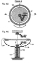
- the substrate holder with the substrate releasably held thereon (63) may be positioned horizontally in said chamber.
- the side walls (61) of said chamber being the walls connecting the topside with the bottom side of said chamber, are oriented such that the angle (64) between said walls and the horizontally positioned substrate holder is smaller than 90 degrees in order to prevent back splashing of the liquid (62) which is removed according to the method of the present invention.
- the liquid leaving the substrate can be collected on theses wall and guided downwards to a drain.
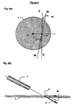
- a substrate (2) is placed on a revolving substrate holder (1).
- Said substrate can be placed in a chamber of a tool comprising at least one chamber.
- the ambient in the chamber is a dry ambient.
- Said substrate holder and the substrate thereon are rotating with a speed which is typically between 2 and 20 or more revolutions per second.
- a movable arm (3) which can be guided between the centre and the edge of the substrate extends above the topside of the substrate. Initially one end of this arm is located near the centre of the rotary movement, i.e. the centre of the substrate.
- Said arm comprises a heat source (4) for locally heating the liquid and a liquid supply system comprising means (5) for supplying a liquid to the substrate.
- Said heat source further comprises at least one nozzle, initially being placed at or near the centre of the substrate, for dispensing a heated gas or a heated vapor or a heated mixture of a gas and a vapor on said substrate.
- Said second supply system further comprises at least one nozzle, being placed more outwards than said nozzle for dispensing said heated gas, for spraying said liquid on said substrate.
- a movable arm comprising fixed nozzles
- movable nozzles on a fixed arm can be used instead of a movable nozzles on a fixed arm can be used.
- the translation speed, v at which the arm, i.e. the nozzles, moves can be adapted to the rotational (angular) speed, ⁇ , of the substrate.
- ⁇ r is the translation distance, being the radial distance over which the liquid-ambient boundary extends radialy during one revolution
- the rotational speed is 1 revolution per second.
- the nozzles are located such that their centre lines will draw concentric circles on the surface with a difference in radius on the order of 5 mm.
- a curved liquid-ambient boundary is formed which is initially located at said centre of the substrate. Then this boundary is slowly guided outwards by moving said arm (3) from the centre to the edge of the substrate to thereby remove the liquid or the solution of said liquid from the topside of said substrate.
- the liquid-ambient boundary is located in between heat source and the nearest nozzle spraying the liquid. Spraying the liquid can be done such that at least locally a sharp and stable curved boundary is obtained, and particularly in case hydrophilic substrates are used the entire surface of the substrate at the outerside of the boundary is kept wet.
- the orientation of the liquid nozzle(s) and of the velocity of the liquid leaving the nozzle will involve optimization of the orientation of the liquid nozzle(s) and of the velocity of the liquid leaving the nozzle.
- the angle (32) between the velocity vector of the liquid (figure 3 (13)) when leaving the nozzle and the velocity vector of the rotating surface (figure 3 (14)) at the point (30) where the liquid flow impinges can be kept small.
- the liquid nozzles can also be slightly oriented outwards, i.e. typically at an angle (33) between 0 degrees and 5 degrees. For removing a liquid having a low contact angle in contact with the surface, it is found sufficient to have only one nozzle for supplying the liquid.
- additional nozzles for spraying liquid can be installed at equal or greater distance from the rotation centre (31).
- the additional nozzles can be turned off as they move over the substrate edge. It may be useful to progressively modulate the flow and the rotation speed as the drying proceeds from the centre towards the edge of the substrate.
- a substrate (2) can be clamped into a ring-shaped substrate holder (11) having an inner diameter larger than the diameter of the substrate. The clamping is done using minimal contact surface.
- the substrate holder or alternatively the substrate itself is placed between at least two revolving means (12) which transmit the rotational force to said substrate holder comprising the substrate or alternatively to said substrate alone.
- Said substrate holder comprising said substrate or said substrate alone can be placed in a chamber of a tool comprising at least one chamber.
- Said substrate is rotating at a speed which is typically between 2 and 40 revolutions per second.
- Two movable arms (3) which can be guided separately or simultaneously between the centre and the edge of the substrate extend above the topside and below the bottomside of the substrate.
- each of these arms comprises a liquid supply system and a heat source being isolated one from the other.
- Said heat source and said liquid supply system are positioned such that at each side the position where the liquid is heated by the heat source is closer to the centre of said rotary movement of said substrate holder than the position where said liquid is applied.
- a liquid-ambient boundary can be formed which is located at said centre of the substrate. Then this boundary is slowly guided outwards by moving said arms (3) from the centre to the edge of the substrate to thereby remove the liquid or the solution of said liquid from the surfaces of said substrate.
- FIG. 4 Another approach for building this rotation system is shown in figure 4.
- a set of arms (18) with a bar of nozzles (19) attached thereon at the bottomside is mounted on a central shaft (15).
- a hollow shaft (16) is rotating.
- the clamping means (17) of the substrate are fixed.
- the set of arms moving over a radius of the substrate comprises at least a first arm and a second arm and can be made compact, i.e. like a man's arm.
- Said first arm is connected to said shaft to rotate about a first axis orthogonal to and through the rotation centre of the substrate holder.
- Said second arm is parallel to but offset from the first arm with the first arm and the second arm being rotatably connected at a joint to rotate about an axis parallel to the first axis.
- the set of arms on the topside can be similar, but no rotation gear is required at the topside.
- the liquid supply system (3) comprises a cup-shaped nozzle (51) which can be guided over the rotating substrate(2) and which is positioned very close to a surface of a substrate. Particularly, the distance between this cup-shaped nozzle and a surface of the substrate is typically about 0.5 mm.
- the liquid e.g. water, can be supplied through the cup.
- said apparatus further comprises a generator of megasonic energy and a transmitter for transmitting said megasonic energy to a surface of the substrate via the liquid being supplied at said surface.
- a megasonic liquid jet or a megasonic arm can be used
Landscapes
- Engineering & Computer Science (AREA)
- Physics & Mathematics (AREA)
- Condensed Matter Physics & Semiconductors (AREA)
- General Physics & Mathematics (AREA)
- Manufacturing & Machinery (AREA)
- Computer Hardware Design (AREA)
- Microelectronics & Electronic Packaging (AREA)
- Power Engineering (AREA)
- Cleaning Or Drying Semiconductors (AREA)
- Weting (AREA)
- Manufacturing Of Printed Wiring (AREA)
- Cleaning By Liquid Or Steam (AREA)
Claims (18)
- Procédé pour retirer un liquide d'au moins une surface d'au moins un substrat (2), caractérisé en ce que ledit procédé comprend les étapes consistant:à soumettre ledit substrat à un mouvement rotatif,à partir d'un système d'alimentation de liquide, à amener un liquide sur au moins une partie de ladite surface dudit substrat,à partir d'une source de chaleur, à chauffer localement le liquide sur ladite partie de ladite surface, tout en amenant ledit liquide, ledit système d'alimentation de liquide et ladite source de chaleur étant positionnés de sorte que ledit chauffage est appliqué plus près du centre de rotation dudit mouvement rotatif que dudit liquide, de sorte qu'au moins localement une frontière entre le liquide et le milieu ambiant définie précisément est créée en réduisant localement la tension de surface dudit liquide, ladite frontière étant localisée entre ledit système d'alimentation de liquide et ladite source de chaleur,à déplacer à la fois ledit système d'alimentation de liquide et ladite source de chaleur dans le but de guider ladite frontière vers l'extérieur, retirant ainsi ledit liquide de ladite surface.
- Procédé selon la revendication 1, comprenant les étapes consistant:à soumettre ledit substrat à un mouvement rotatif,à partir d'un système d'alimentation de liquide, à amener un liquide sur ladite surface dudit substrat, au niveau ou très près du centre de rotation dudit mouvement rotatif,à mettre en marche ladite source de chaleur, localisée adjacente audit système d'alimentation de liquide, chauffant ainsi localement le liquide adjacent audit centre de rotation,à déplacer ledit système d'alimentation de liquide hors dudit centre, tout en déplaçant ladite source de chaleur pour amener de la chaleur au liquide au niveau dudit centre, formant ainsi ladite frontière,à déplacer à la fois ledit système d'alimentation de liquide et ladite source de chaleur dans le but de guider ladite frontière vers l'extérieur, retirant ainsi ledit liquide de ladite surface.
- Procédé selon la revendication 1 ou 2, dans lequel ledit mouvement rotatif est effectué à une vitesse pour guider ladite frontière entre le liquide et le milieu ambiant sur ladite surface dudit substrat (2).
- Procédé selon la revendication 1, dans lequel ledit mouvement rotatif est appliqué sur un seul substrat de sorte que ledit substrat tourne autour de son propre centre.
- Procédé selon la revendication 4, dans lequel la vitesse de rotation est dans la gamme comprise entre 2 et 40 tours par seconde.
- Procédé selon la revendication 1, dans lequel ledit chauffage est réalisé au moyen d'une distribution d'un gaz chauffé ou d'une vapeur chauffée ou d'un mélange chauffé d'un gaz et d'une vapeur.
- Procédé selon la revendication 1, dans lequel ledit chauffage est réalisé au moyen d'une irradiation avec un faisceau énergétique.
- Procédé selon la revendication 1, dans lequel ledit liquide est un liquide du groupe constitué d'un liquide de gravure, d'un liquide de nettoyage ou d'un liquide de rinçage.
- Procédé selon la revendication 1, dans lequel ledit liquide est une solution aqueuse diluée.
- Procédé selon la revendication 8, dans lequel ledit liquide de nettoyage comprend un mélange de NH4OH, H2O2 et H2O; ou comprend un mélange de HCl, H2O2 et H2O; ou comprend HCl dilué; ou comprend un mélange contenant O3.
- Procédé selon la revendication 8, dans lequel ledit liquide de rinçage comprend H2O; ou un mélange de H2O et d'un acide, ledit mélange ayant un pH entre 2 et 6.
- Procédé selon la revendication 1, pour retirer un liquide d'une première surface et d'une deuxième surface d'au moins un substrat, ledit procédé comprenant l'étape consistant à soumettre ledit substrat à un mouvement rotatif et à effectuer le reste des étapes de procédé de la revendication 1 pour ladite première surface et ladite deuxième surface.
- Appareil pour retirer un liquide d'au moins une surface d'au moins un substrat (2) selon le procédé selon l'une quelconque des revendications 1 à 12, ledit appareil comprenant:un porte-substrat (1) qui peut être soumis à un mouvement rotatif, ledit substrat étant porté de façon détachable par ledit porte-substrat;au moins un système d'alimentation de liquide (5) pour l'application d'un liquide sur au moins une partie de ladite surface dudit substrat;au moins une source de chaleur (4), localisée adjacente audit système d'alimentation de liquide, pour chauffer localement ledit liquide, et positionnée de sorte que ledit chauffage est appliqué plus près du centre dudit mouvement rotatif dudit porte-substrat que dudit liquide.
- Appareil selon la revendication 13, comprenant en outre une chambre dans laquelle ledit porte-substrat est positionné, ladite chambre étant conçue de manière à éviter un éclaboussement dudit liquide sur ladite surface dudit substrat.
- Appareil selon la revendication 13, dans lequel ladite source de chaleur comprend au moins une buse pour distribuer un gaz chauffé, ou une vapeur chauffée, ou un mélange chauffé d'une vapeur et d'un gaz sur ladite surface dudit substrat et ledit système d'alimentation de liquide comprend au moins une buse pour l'application dudit liquide sur ladite partie de ladite surface dudit substrat.
- Appareil selon la revendication 15, dans lequel lesdites buses sont montées sur un bras (3), ledit bras étant mobile par rapport audit porte-substrat.
- Appareil selon la revendication 15, dans lequel lesdites buses sont montées sur un bras, ledit bras étant fixe, mais lesdites buses étant mobiles par rapport audit bras.
- Appareil selon la revendication 13, dans lequel ladite source de chaleur est une source d'énergie radiante.
Applications Claiming Priority (9)
| Application Number | Priority Date | Filing Date | Title |
|---|---|---|---|
| US5992997P | 1997-09-24 | 1997-09-24 | |
| US59929P | 1997-09-24 | ||
| EP98870056A EP0905746A1 (fr) | 1997-09-24 | 1998-03-20 | Méthode pour enlever un liquide de la surface d'un substrat tournant |
| EP98870056 | 1998-03-20 | ||
| US7968898P | 1998-03-27 | 1998-03-27 | |
| US79688P | 1998-03-27 | ||
| US9803898P | 1998-08-27 | 1998-08-27 | |
| US98038P | 1998-08-27 | ||
| PCT/BE1998/000140 WO1999016109A1 (fr) | 1997-09-24 | 1998-09-24 | Procede et dispositif permettant de chasser un liquide d'une surface |
Publications (2)
| Publication Number | Publication Date |
|---|---|
| EP0970511A1 EP0970511A1 (fr) | 2000-01-12 |
| EP0970511B1 true EP0970511B1 (fr) | 2005-01-12 |
Family
ID=27443760
Family Applications (1)
| Application Number | Title | Priority Date | Filing Date |
|---|---|---|---|
| EP98944906A Expired - Lifetime EP0970511B1 (fr) | 1997-09-24 | 1998-09-24 | Procede et dispositif permettant de chasser un liquide d'une surface |
Country Status (5)
| Country | Link |
|---|---|
| EP (1) | EP0970511B1 (fr) |
| JP (1) | JP4017680B2 (fr) |
| AT (1) | ATE287126T1 (fr) |
| DE (1) | DE69828592T8 (fr) |
| WO (1) | WO1999016109A1 (fr) |
Cited By (1)
| Publication number | Priority date | Publication date | Assignee | Title |
|---|---|---|---|---|
| US10720343B2 (en) | 2016-05-31 | 2020-07-21 | Lam Research Ag | Method and apparatus for processing wafer-shaped articles |
Families Citing this family (50)
| Publication number | Priority date | Publication date | Assignee | Title |
|---|---|---|---|---|
| US7234477B2 (en) | 2000-06-30 | 2007-06-26 | Lam Research Corporation | Method and apparatus for drying semiconductor wafer surfaces using a plurality of inlets and outlets held in close proximity to the wafer surfaces |
| US7584761B1 (en) | 2000-06-30 | 2009-09-08 | Lam Research Corporation | Wafer edge surface treatment with liquid meniscus |
| US7000622B2 (en) * | 2002-09-30 | 2006-02-21 | Lam Research Corporation | Methods and systems for processing a bevel edge of a substrate using a dynamic liquid meniscus |
| KR100416590B1 (ko) * | 2001-01-13 | 2004-02-05 | 삼성전자주식회사 | 반도체 웨이퍼 세정장치 및 이를 이용한 웨이퍼 세정방법 |
| US6928751B2 (en) | 2001-06-12 | 2005-08-16 | Goldfinger Technologies, Llc | Megasonic cleaner and dryer system |
| US7100304B2 (en) * | 2001-06-12 | 2006-09-05 | Akrion Technologies, Inc. | Megasonic cleaner and dryer |
| DE10200525A1 (de) * | 2002-01-09 | 2003-10-23 | Mattson Wet Products Gmbh | Vorrichtung und Verfahren zum Behandeln von scheibenförmigen Substraten |
| US7367345B1 (en) | 2002-09-30 | 2008-05-06 | Lam Research Corporation | Apparatus and method for providing a confined liquid for immersion lithography |
| US6988327B2 (en) | 2002-09-30 | 2006-01-24 | Lam Research Corporation | Methods and systems for processing a substrate using a dynamic liquid meniscus |
| US7513262B2 (en) | 2002-09-30 | 2009-04-07 | Lam Research Corporation | Substrate meniscus interface and methods for operation |
| US7614411B2 (en) | 2002-09-30 | 2009-11-10 | Lam Research Corporation | Controls of ambient environment during wafer drying using proximity head |
| US7389783B2 (en) | 2002-09-30 | 2008-06-24 | Lam Research Corporation | Proximity meniscus manifold |
| US7153400B2 (en) | 2002-09-30 | 2006-12-26 | Lam Research Corporation | Apparatus and method for depositing and planarizing thin films of semiconductor wafers |
| US7069937B2 (en) | 2002-09-30 | 2006-07-04 | Lam Research Corporation | Vertical proximity processor |
| US8236382B2 (en) | 2002-09-30 | 2012-08-07 | Lam Research Corporation | Proximity substrate preparation sequence, and method, apparatus, and system for implementing the same |
| US6954993B1 (en) | 2002-09-30 | 2005-10-18 | Lam Research Corporation | Concentric proximity processing head |
| US7383843B2 (en) | 2002-09-30 | 2008-06-10 | Lam Research Corporation | Method and apparatus for processing wafer surfaces using thin, high velocity fluid layer |
| US7093375B2 (en) | 2002-09-30 | 2006-08-22 | Lam Research Corporation | Apparatus and method for utilizing a meniscus in substrate processing |
| US7329321B2 (en) | 2002-09-30 | 2008-02-12 | Lam Research Corporation | Enhanced wafer cleaning method |
| WO2004030051A2 (fr) * | 2002-09-30 | 2004-04-08 | Lam Research Corporation | Systeme de traitement d'un substrat par generation d'un menisque, d'un vide, de vapeur d'alcool isopropylique et sechage |
| US7632376B1 (en) | 2002-09-30 | 2009-12-15 | Lam Research Corporation | Method and apparatus for atomic layer deposition (ALD) in a proximity system |
| US7997288B2 (en) | 2002-09-30 | 2011-08-16 | Lam Research Corporation | Single phase proximity head having a controlled meniscus for treating a substrate |
| US7045018B2 (en) | 2002-09-30 | 2006-05-16 | Lam Research Corporation | Substrate brush scrubbing and proximity cleaning-drying sequence using compatible chemistries, and method, apparatus, and system for implementing the same |
| US7240679B2 (en) | 2002-09-30 | 2007-07-10 | Lam Research Corporation | System for substrate processing with meniscus, vacuum, IPA vapor, drying manifold |
| US7293571B2 (en) | 2002-09-30 | 2007-11-13 | Lam Research Corporation | Substrate proximity processing housing and insert for generating a fluid meniscus |
| KR101055997B1 (ko) * | 2002-09-30 | 2011-08-11 | 램 리써치 코포레이션 | 반도체웨이퍼표면에 근접하여 고정된 다수의 입구 및 출구를 사용하여 반도체웨이퍼표면을 건조하는 방법 및 장치 |
| US7704367B2 (en) | 2004-06-28 | 2010-04-27 | Lam Research Corporation | Method and apparatus for plating semiconductor wafers |
| US7675000B2 (en) | 2003-06-24 | 2010-03-09 | Lam Research Corporation | System method and apparatus for dry-in, dry-out, low defect laser dicing using proximity technology |
| US7170190B1 (en) | 2003-12-16 | 2007-01-30 | Lam Research Corporation | Apparatus for oscillating a head and methods for implementing the same |
| US7350315B2 (en) * | 2003-12-22 | 2008-04-01 | Lam Research Corporation | Edge wheel dry manifold |
| US8062471B2 (en) | 2004-03-31 | 2011-11-22 | Lam Research Corporation | Proximity head heating method and apparatus |
| US7089687B2 (en) | 2004-09-30 | 2006-08-15 | Lam Research Corporation | Wafer edge wheel with drying function |
| US8480810B2 (en) | 2005-12-30 | 2013-07-09 | Lam Research Corporation | Method and apparatus for particle removal |
| US7928366B2 (en) | 2006-10-06 | 2011-04-19 | Lam Research Corporation | Methods of and apparatus for accessing a process chamber using a dual zone gas injector with improved optical access |
| US8813764B2 (en) | 2009-05-29 | 2014-08-26 | Lam Research Corporation | Method and apparatus for physical confinement of a liquid meniscus over a semiconductor wafer |
| JP4810411B2 (ja) | 2006-11-30 | 2011-11-09 | 東京応化工業株式会社 | 処理装置 |
| US8146902B2 (en) | 2006-12-21 | 2012-04-03 | Lam Research Corporation | Hybrid composite wafer carrier for wet clean equipment |
| US8464736B1 (en) | 2007-03-30 | 2013-06-18 | Lam Research Corporation | Reclaim chemistry |
| US7975708B2 (en) | 2007-03-30 | 2011-07-12 | Lam Research Corporation | Proximity head with angled vacuum conduit system, apparatus and method |
| US8388762B2 (en) | 2007-05-02 | 2013-03-05 | Lam Research Corporation | Substrate cleaning technique employing multi-phase solution |
| US8141566B2 (en) | 2007-06-19 | 2012-03-27 | Lam Research Corporation | System, method and apparatus for maintaining separation of liquids in a controlled meniscus |
| US20110289795A1 (en) | 2010-02-16 | 2011-12-01 | Tomoatsu Ishibashi | Substrate drying apparatus, substrate drying method and control program |
| JP5538102B2 (ja) | 2010-07-07 | 2014-07-02 | 株式会社Sokudo | 基板洗浄方法および基板洗浄装置 |
| JP2014130883A (ja) * | 2012-12-28 | 2014-07-10 | Ebara Corp | 基板洗浄装置及び基板洗浄方法 |
| JP6376553B2 (ja) * | 2014-03-26 | 2018-08-22 | 株式会社Screenホールディングス | 基板処理装置 |
| TWI667722B (zh) * | 2014-02-27 | 2019-08-01 | 日商斯克林集團公司 | 基板處理裝置 |
| JP6376554B2 (ja) * | 2014-03-26 | 2018-08-22 | 株式会社Screenホールディングス | 基板処理装置 |
| KR102308587B1 (ko) | 2014-03-19 | 2021-10-01 | 가부시키가이샤 스크린 홀딩스 | 기판 처리 장치 및 기판 처리 방법 |
| CN105826219B (zh) | 2015-01-23 | 2019-01-04 | 株式会社思可林集团 | 基板处理方法、基板处理装置和流体喷嘴 |
| JP6461621B2 (ja) * | 2015-01-23 | 2019-01-30 | 株式会社Screenホールディングス | 基板処理方法および基板処理装置 |
Citations (3)
| Publication number | Priority date | Publication date | Assignee | Title |
|---|---|---|---|---|
| WO1996010463A1 (fr) * | 1994-10-04 | 1996-04-11 | Kunze Concewitz Horst | Procede et dispositif de nettoyage approfondi de surfaces |
| EP0905747A1 (fr) * | 1997-09-24 | 1999-03-31 | Interuniversitair Micro-Elektronica Centrum Vzw | Méthode et dispositif pour retirer un liquide de la surface d'un substrat tournant |
| EP0905746A1 (fr) * | 1997-09-24 | 1999-03-31 | Interuniversitair Micro-Elektronica Centrum Vzw | Méthode pour enlever un liquide de la surface d'un substrat tournant |
Family Cites Families (3)
| Publication number | Priority date | Publication date | Assignee | Title |
|---|---|---|---|---|
| US4027686A (en) * | 1973-01-02 | 1977-06-07 | Texas Instruments Incorporated | Method and apparatus for cleaning the surface of a semiconductor slice with a liquid spray of de-ionized water |
| JP3351082B2 (ja) * | 1994-01-14 | 2002-11-25 | ソニー株式会社 | 基板乾燥方法と、基板乾燥槽と、ウェーハ洗浄装置および半導体装置の製造方法 |
| JPH09162159A (ja) * | 1995-12-05 | 1997-06-20 | Dainippon Screen Mfg Co Ltd | 回転式基板乾燥装置 |
-
1998
- 1998-09-24 WO PCT/BE1998/000140 patent/WO1999016109A1/fr active IP Right Grant
- 1998-09-24 AT AT98944906T patent/ATE287126T1/de not_active IP Right Cessation
- 1998-09-24 JP JP51835899A patent/JP4017680B2/ja not_active Expired - Lifetime
- 1998-09-24 DE DE69828592T patent/DE69828592T8/de active Active
- 1998-09-24 EP EP98944906A patent/EP0970511B1/fr not_active Expired - Lifetime
Patent Citations (3)
| Publication number | Priority date | Publication date | Assignee | Title |
|---|---|---|---|---|
| WO1996010463A1 (fr) * | 1994-10-04 | 1996-04-11 | Kunze Concewitz Horst | Procede et dispositif de nettoyage approfondi de surfaces |
| EP0905747A1 (fr) * | 1997-09-24 | 1999-03-31 | Interuniversitair Micro-Elektronica Centrum Vzw | Méthode et dispositif pour retirer un liquide de la surface d'un substrat tournant |
| EP0905746A1 (fr) * | 1997-09-24 | 1999-03-31 | Interuniversitair Micro-Elektronica Centrum Vzw | Méthode pour enlever un liquide de la surface d'un substrat tournant |
Cited By (2)
| Publication number | Priority date | Publication date | Assignee | Title |
|---|---|---|---|---|
| US10720343B2 (en) | 2016-05-31 | 2020-07-21 | Lam Research Ag | Method and apparatus for processing wafer-shaped articles |
| US10861719B2 (en) | 2016-05-31 | 2020-12-08 | Lam Research Ag | Method and apparatus for processing wafer-shaped articles |
Also Published As
| Publication number | Publication date |
|---|---|
| DE69828592T2 (de) | 2006-03-23 |
| ATE287126T1 (de) | 2005-01-15 |
| JP2001506061A (ja) | 2001-05-08 |
| JP4017680B2 (ja) | 2007-12-05 |
| WO1999016109A1 (fr) | 1999-04-01 |
| DE69828592T8 (de) | 2006-06-08 |
| EP0970511A1 (fr) | 2000-01-12 |
| DE69828592D1 (de) | 2005-02-17 |
Similar Documents
| Publication | Publication Date | Title |
|---|---|---|
| EP0970511B1 (fr) | Procede et dispositif permettant de chasser un liquide d'une surface | |
| US6821349B2 (en) | Method and apparatus for removing a liquid from a surface | |
| EP0905747B1 (fr) | Méthode et dispositif pour enlever un liquide de la surface d'un substrat tournant | |
| US6491764B2 (en) | Method and apparatus for removing a liquid from a surface of a rotating substrate | |
| EP0905746A1 (fr) | Méthode pour enlever un liquide de la surface d'un substrat tournant | |
| KR101873100B1 (ko) | 기판 세정 방법 및 기판 세정 장치 | |
| US7021319B2 (en) | Assisted rinsing in a single wafer cleaning process | |
| JP4769790B2 (ja) | 基板処理方法、基板処理装置及び制御プログラム | |
| US6431184B1 (en) | Apparatus and method for washing substrate | |
| KR101668212B1 (ko) | 액처리 방법, 액처리 장치 및 기억매체 | |
| US20080308131A1 (en) | Method and apparatus for cleaning and driving wafers | |
| US9418831B2 (en) | Method for precision cleaning and drying flat objects | |
| US20050124518A1 (en) | Substrate treating apparatus | |
| US7527698B2 (en) | Method and apparatus for removing a liquid from a surface of a substrate | |
| KR100468110B1 (ko) | 웨이퍼 처리 장치 | |
| JP2005268308A (ja) | レジスト剥離方法およびレジスト剥離装置 | |
| JP4634490B2 (ja) | 回転基材の表面から液体を除去する方法および装置 | |
| JP2005142309A (ja) | 基板の洗浄方法、洗浄装置および洗浄システム | |
| JP2000003897A (ja) | 基板洗浄方法及び基板洗浄装置 | |
| JP3711010B2 (ja) | 基板処理装置および基板処理方法 | |
| JP2002190465A (ja) | 半導体ウエハの表面処理方法及びその装置 | |
| JPH0620063B2 (ja) | 半導体基板の洗浄装置 |
Legal Events
| Date | Code | Title | Description |
|---|---|---|---|
| PUAI | Public reference made under article 153(3) epc to a published international application that has entered the european phase |
Free format text: ORIGINAL CODE: 0009012 |
|
| 17P | Request for examination filed |
Effective date: 19990914 |
|
| AK | Designated contracting states |
Kind code of ref document: A1 Designated state(s): AT BE CH CY DE DK ES FI FR GB GR IE IT LI LU MC NL PT SE |
|
| 17Q | First examination report despatched |
Effective date: 20030528 |
|
| GRAP | Despatch of communication of intention to grant a patent |
Free format text: ORIGINAL CODE: EPIDOSNIGR1 |
|
| GRAS | Grant fee paid |
Free format text: ORIGINAL CODE: EPIDOSNIGR3 |
|
| GRAA | (expected) grant |
Free format text: ORIGINAL CODE: 0009210 |
|
| AK | Designated contracting states |
Kind code of ref document: B1 Designated state(s): AT BE DE FR GB IT NL |
|
| PG25 | Lapsed in a contracting state [announced via postgrant information from national office to epo] |
Ref country code: NL Free format text: LAPSE BECAUSE OF FAILURE TO SUBMIT A TRANSLATION OF THE DESCRIPTION OR TO PAY THE FEE WITHIN THE PRESCRIBED TIME-LIMIT Effective date: 20050112 Ref country code: IT Free format text: LAPSE BECAUSE OF FAILURE TO SUBMIT A TRANSLATION OF THE DESCRIPTION OR TO PAY THE FEE WITHIN THE PRE;WARNING: LAPSES OF ITALIAN PATENTS WITH EFFECTIVE DATE BEFORE 2007 MAY HAVE OCCURRED AT ANY TIME BEFORE 2007. THE CORRECT EFFECTIVE DATE MAY BE DIFFERENT FROM THE ONE RECORDED.SCRIBED TIME-LIMIT Effective date: 20050112 Ref country code: BE Free format text: LAPSE BECAUSE OF FAILURE TO SUBMIT A TRANSLATION OF THE DESCRIPTION OR TO PAY THE FEE WITHIN THE PRESCRIBED TIME-LIMIT Effective date: 20050112 Ref country code: AT Free format text: LAPSE BECAUSE OF FAILURE TO SUBMIT A TRANSLATION OF THE DESCRIPTION OR TO PAY THE FEE WITHIN THE PRESCRIBED TIME-LIMIT Effective date: 20050112 |
|
| REG | Reference to a national code |
Ref country code: GB Ref legal event code: FG4D |
|
| REF | Corresponds to: |
Ref document number: 69828592 Country of ref document: DE Date of ref document: 20050217 Kind code of ref document: P |
|
| NLV1 | Nl: lapsed or annulled due to failure to fulfill the requirements of art. 29p and 29m of the patents act | ||
| PLBE | No opposition filed within time limit |
Free format text: ORIGINAL CODE: 0009261 |
|
| STAA | Information on the status of an ep patent application or granted ep patent |
Free format text: STATUS: NO OPPOSITION FILED WITHIN TIME LIMIT |
|
| ET | Fr: translation filed | ||
| 26N | No opposition filed |
Effective date: 20051013 |
|
| REG | Reference to a national code |
Ref country code: FR Ref legal event code: PLFP Year of fee payment: 19 |
|
| REG | Reference to a national code |
Ref country code: FR Ref legal event code: PLFP Year of fee payment: 20 |
|
| PGFP | Annual fee paid to national office [announced via postgrant information from national office to epo] |
Ref country code: GB Payment date: 20170821 Year of fee payment: 20 Ref country code: DE Payment date: 20170821 Year of fee payment: 20 Ref country code: FR Payment date: 20170822 Year of fee payment: 20 |
|
| REG | Reference to a national code |
Ref country code: DE Ref legal event code: R071 Ref document number: 69828592 Country of ref document: DE |
|
| REG | Reference to a national code |
Ref country code: GB Ref legal event code: PE20 Expiry date: 20180923 |
|
| PG25 | Lapsed in a contracting state [announced via postgrant information from national office to epo] |
Ref country code: GB Free format text: LAPSE BECAUSE OF EXPIRATION OF PROTECTION Effective date: 20180923 |