EP0969693A2 - Verfahren und Schaltung zur Klangeindrucksverbesserung in einem Unterhaltungselektronikgerät - Google Patents
Verfahren und Schaltung zur Klangeindrucksverbesserung in einem Unterhaltungselektronikgerät Download PDFInfo
- Publication number
- EP0969693A2 EP0969693A2 EP99111867A EP99111867A EP0969693A2 EP 0969693 A2 EP0969693 A2 EP 0969693A2 EP 99111867 A EP99111867 A EP 99111867A EP 99111867 A EP99111867 A EP 99111867A EP 0969693 A2 EP0969693 A2 EP 0969693A2
- Authority
- EP
- European Patent Office
- Prior art keywords
- housing
- memory
- control unit
- audio
- data
- Prior art date
- Legal status (The legal status is an assumption and is not a legal conclusion. Google has not performed a legal analysis and makes no representation as to the accuracy of the status listed.)
- Withdrawn
Links
Images

Classifications
-
- H—ELECTRICITY
- H04—ELECTRIC COMMUNICATION TECHNIQUE
- H04R—LOUDSPEAKERS, MICROPHONES, GRAMOPHONE PICK-UPS OR LIKE ACOUSTIC ELECTROMECHANICAL TRANSDUCERS; ELECTRIC HEARING AIDS; PUBLIC ADDRESS SYSTEMS
- H04R3/00—Circuits for transducers
- H04R3/04—Circuits for transducers for correcting frequency response
-
- H—ELECTRICITY
- H04—ELECTRIC COMMUNICATION TECHNIQUE
- H04R—LOUDSPEAKERS, MICROPHONES, GRAMOPHONE PICK-UPS OR LIKE ACOUSTIC ELECTROMECHANICAL TRANSDUCERS; ELECTRIC HEARING AIDS; PUBLIC ADDRESS SYSTEMS
- H04R2499/00—Aspects covered by H04R or H04S not otherwise provided for in their subgroups
- H04R2499/10—General applications
- H04R2499/11—Transducers incorporated or for use in hand-held devices, e.g. mobile phones, PDA's, camera's
-
- H—ELECTRICITY
- H04—ELECTRIC COMMUNICATION TECHNIQUE
- H04R—LOUDSPEAKERS, MICROPHONES, GRAMOPHONE PICK-UPS OR LIKE ACOUSTIC ELECTROMECHANICAL TRANSDUCERS; ELECTRIC HEARING AIDS; PUBLIC ADDRESS SYSTEMS
- H04R2499/00—Aspects covered by H04R or H04S not otherwise provided for in their subgroups
- H04R2499/10—General applications
- H04R2499/15—Transducers incorporated in visual displaying devices, e.g. televisions, computer displays, laptops
Definitions
- the invention is based on a method and a circuit for improving the sound impression in a consumer electronics device.
- the invention is based on the object of providing a method and/or a circuit for improving the sound impression in a consumer electronics device. This object is achieved by means of the features specified in Claim 1. Advantageous improvements of the invention are specified in the subclaims.
- the method according to the invention for improving the sound impression in a consumer electronics device having a housing, a control unit, an audio input signal, an audio output signal and a memory is distinguished by the fact that housing-specific sound-characteristic data are stored in the memory and that the control unit changes the audio input signal with reference to the stored data in such a way that the audio output signal is changed.
- This has the advantage that an improvement in the sound impression is acquired in a simple way.
- the housing data relating to each housing are stored in the memory during production so that when the device is activated by the user, the user is provided with the sound impression which is considered the optimum one in a normal situation.
- control unit is formed from a microprocessor and/or an integrated circuit for audio signals.
- the microprocessor operates with integrated circuits for audio signals.
- a microprocessor already contains this integrated circuit. In this way, a compact design is made possible. If the microprocessor does not contain this integrated circuit, a better degree of compatibility is provided since possible other integrated circuits, which have been improved at a later date, for audio signals and/or more powerful microprocessors can be used.
- the method is also distinguished by the fact that the control unit is connected to an equalizer and/or that an equalizer is implemented.
- the control unit may contain an equalizer or be connected to one.
- the equalizer is preferably implemented in the form of software, i.e. the user can modify the individual areas of the frequency response on the screen by remote control. This procedure enables him to modify the sound-characteristic data to values which are the most pleasant for him.
- this equalizer could be a dual band equalizer. There are no upper limits on the division of the equalizer for the band widths, five bands being preferably used.
- the method is distinguished by the fact that the housing-specific sound-characteristic data are stored in the memory, for example in an integrated circuit, and/or that during the production process, the data are stored in the memory by means of the control unit during the production process, and/or that the data are already stored in the memory before production.
- the housing-specific sound-characteristic data can, as described above, be fed into the memory in various ways, it is important that the data are present in the memory before the user activates the television, or otherwise he would have to set the sound-characteristic data of his device manually. This could be carried out by means of the equalizer. This means that a leaflet containing the optimum equalizer setting is enclosed with each type of device so that the user can set the device in this way.
- the method is distinguished by the fact that the housing-specific sound-characteristic data are arranged in the audio signal path by means of a circuit.
- a circuit in the form of hardware it is also possible for a circuit in the form of hardware, to be positioned in the audio signal path so that the housing-specific sound-characteristic data would influence the signal path in this way.
- a circuit according to the invention for improving the sound impression in a consumer electronics device having a housing, a control unit, an audio input signal, an audio output signal and a memory is distinguished by the fact that the memory contains housing-specific sound-characteristic data, and that the control unit changes the audio input signal with reference to the stored data in such a way that the signal profile of the audio output signal can be changed.
- the housing data which are to be used are the data of the boxes since the latter adversely affect the sound impression.
- the equalizer is actuated, for example, not by means of software using the screen as described previously but rather controlled by means of controllers.
- This also constitutes an alternative solution for a television set, and the software solution for the equalizer certainly gives a more pleasant impression.
- any loudspeaker box it is also possible for any loudspeaker box to be equipped with such housing-specific sound impressions so that the user of an audio system or of a television set etc. can set the data using the setting facilities of the respective device. This would be a simple method of ensuring that an optimum sound impression is acquired from a housing.
- Fig. 1 shows a block diagram of the method and/or circuit according to the invention for use, for example, in a television set. It contains an antenna input signal IN which is fed to the IF circuit IF via the tuner TU. The audio IF element is then passed to the integrated circuit IC. The integrated circuit IC receives a control signal from the microprocessor ⁇ P via the I 2 C bus and further audio signals, for example from the Scart sockets via the AF input. The integrated circuit IC is connected to an equalizer EQUA or contains the equalizer function as indicated here by broken lines. The audio signal l, r is then fed from the integrated circuit to the corresponding loudspeaker ll, lr via appropriate amplifier circuits vl, vr.
- the microprocessor receives the housing-specific sound-characteristic data from the unit PRO during production. These data which are referred to below as data are passed on to the memory MEM by the microprocessor. As an alternative to this, it is also possible for the data to be fed directly into the memory MEM by the unit PRO during production. As a further alternative, the data are already stored in the memory MEM before the device is produced and are thus already present during production. If the equalizer EQUA is not contained in the integrated circuit, it could be actuated by it. However, it is also possible for the microprocessor ⁇ P to carry out an actuation operation by means of the I 2 C bus.
- Fig. 2a An ideal profile of the acoustic signal is displayed in Fig. 2a.
- the transmitted frequency range extends between 20 Hz and 15 kHz.
- 0 dB is given as a reference value which should, as a rule, remain constant.
- This 0 dB reference value could be given, for example, a power of 1.5 or 10 Watts, it serves merely as a reference value.
- Fig. 2b shows how a glitch of about 3 dB appears at the upper end of the frequency range as a result of the shape of the housing. This means that the user perceives a duller sound.
- Fig. 2c shows how a boost of about 3 dB is carried out by electrical means precisely at the point at which the drop owing to the housing takes place.
- Fig. 2d shows that virtually an optimum profile is acquired. This means that the loudspeakers ll, lr can provide the user with an improved sound impression.
- the manufacturer obtains the housing data by performing measurements with the housing in order to determine where the glitches in the frequency response are situated.
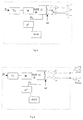
- Fig. 3 shows a development of the block diagram diagram from Fig. 1.
- An assembly B which also makes it possible to improve the sound impression, has now been integrated in the audio signal path.
- the assembly is composed, for example, of inductors, resistors and capacitors which change the frequency response in accordance with the housing data. This means that the assembly changes the electrical signal in such a way that, depending on the housing data, the signal is boosted at appropriate points in order to bring about compensation, as already described with reference to Fig. 2.
- Fig. 4 shows a solution which can be used in a television set in which the loudspeakers ll, lr are arranged externally.
- the housing data to be used are the data of the boxes because they adversely affect the sound impression.
- the equalizer can also be actuated by software, via the screen.
Landscapes
- Physics & Mathematics (AREA)
- Engineering & Computer Science (AREA)
- Acoustics & Sound (AREA)
- Signal Processing (AREA)
- Circuit For Audible Band Transducer (AREA)
- Tone Control, Compression And Expansion, Limiting Amplitude (AREA)
- Details Of Audible-Bandwidth Transducers (AREA)
Applications Claiming Priority (2)
| Application Number | Priority Date | Filing Date | Title |
|---|---|---|---|
| DE19829009 | 1998-06-30 | ||
| DE19829009A DE19829009A1 (de) | 1998-06-30 | 1998-06-30 | Verfahren und Schaltung zur Verbesserung des Klangbildes bei einem Gerät der Unterhaltungselektronik |
Publications (1)
| Publication Number | Publication Date |
|---|---|
| EP0969693A2 true EP0969693A2 (de) | 2000-01-05 |
Family
ID=7872409
Family Applications (1)
| Application Number | Title | Priority Date | Filing Date |
|---|---|---|---|
| EP99111867A Withdrawn EP0969693A2 (de) | 1998-06-30 | 1999-06-21 | Verfahren und Schaltung zur Klangeindrucksverbesserung in einem Unterhaltungselektronikgerät |
Country Status (4)
| Country | Link |
|---|---|
| US (1) | US20010040971A1 (de) |
| EP (1) | EP0969693A2 (de) |
| JP (1) | JP2000035789A (de) |
| DE (1) | DE19829009A1 (de) |
Family Cites Families (2)
| Publication number | Priority date | Publication date | Assignee | Title |
|---|---|---|---|---|
| DE3507841A1 (de) * | 1985-03-06 | 1986-09-11 | Wolfgang 7320 Göppingen Paech | Individuelle vorverzerrung von audiosignalen fuer lautsprecherboxen |
| KR100230102B1 (ko) * | 1996-12-11 | 1999-11-15 | 구자홍 | 볼륨레벨에 따른 음성조정방법 |
-
1998
- 1998-06-30 DE DE19829009A patent/DE19829009A1/de not_active Withdrawn
-
1999
- 1999-06-21 EP EP99111867A patent/EP0969693A2/de not_active Withdrawn
- 1999-06-28 US US09/340,899 patent/US20010040971A1/en not_active Abandoned
- 1999-06-29 JP JP11184106A patent/JP2000035789A/ja active Pending
Also Published As
| Publication number | Publication date |
|---|---|
| DE19829009A1 (de) | 2000-01-05 |
| JP2000035789A (ja) | 2000-02-02 |
| US20010040971A1 (en) | 2001-11-15 |
Similar Documents
| Publication | Publication Date | Title |
|---|---|---|
| US5285500A (en) | Car amplifier with optional plug-in modules | |
| EP1428411B2 (de) | Verfahren und vorrichtung zur steuerung der basswiedergabe von audiosignalen in elektroakustischen wandlern | |
| JPH06269076A (ja) | 同軸型スピーカ | |
| EP1104645B1 (de) | Hörgerät mit einer einrichtung zur unterdrückung von elektromagnetischen störsignalen sowie verfahren zur unterdrückung von elektromagnetischen störsignalen in hörgeräten | |
| US7905006B2 (en) | Method of manufacturing faceplate for in-the-ear hearing aid | |
| JP2003209441A (ja) | 車載用パワーアンプ及びその電圧供給装置 | |
| US20170170796A1 (en) | Electronic device for adjusting an equalizer setting according to a user age, sound playback device, and equalizer adjustment method | |
| CN111787479B (zh) | 一种修正tws耳机听感的方法和系统 | |
| EP0969693A2 (de) | Verfahren und Schaltung zur Klangeindrucksverbesserung in einem Unterhaltungselektronikgerät | |
| US20040225388A1 (en) | Fully digitized audio system | |
| US10506340B2 (en) | Digital signal processor for audio, in-vehicle audio system and electronic apparatus including the same | |
| CN219107631U (zh) | 音频处理电路、车载播放器、蓝牙播放系统及交通工具 | |
| KR101078475B1 (ko) | 스피커 튜닝기 | |
| US7242780B2 (en) | Audio signal cable with passive network | |
| JP2001251694A (ja) | 車載用スピーカのネットワーク取付構造 | |
| JP2005117361A (ja) | 音響装置及び音響装置の音響特性設定方法 | |
| DE19630330C2 (de) | Audiosignalprozessor | |
| JP3319970B2 (ja) | グラフィックイコライザ装置 | |
| JPH0736526B2 (ja) | 無線通信機のノイズ低減方式 | |
| EP1079663A2 (de) | Frequenzgangkompensationssystem für planar Lautsprecher | |
| KR102527770B1 (ko) | 알터네이터의 전원노이즈를 효율적으로 필터링하여 전기장치에 공급하기 위한 퓨즈교체 방식의 라우드니스형 노이즈필터 | |
| CN209395745U (zh) | 调谐单元电路及车载娱乐系统 | |
| US20170134859A1 (en) | Apparatus and method for providing at least one speaker assembly | |
| JP2004023148A (ja) | 音出力装置 | |
| JP3955974B2 (ja) | スピーカネットワーク装置 |
Legal Events
| Date | Code | Title | Description |
|---|---|---|---|
| PUAI | Public reference made under article 153(3) epc to a published international application that has entered the european phase |
Free format text: ORIGINAL CODE: 0009012 |
|
| AK | Designated contracting states |
Kind code of ref document: A2 Designated state(s): AT BE CH CY DE DK ES FI FR GB GR IE IT LI LU MC NL PT SE |
|
| AX | Request for extension of the european patent |
Free format text: AL;LT;LV;MK;RO;SI |
|
| STAA | Information on the status of an ep patent application or granted ep patent |
Free format text: STATUS: THE APPLICATION IS DEEMED TO BE WITHDRAWN |
|
| 18D | Application deemed to be withdrawn |
Effective date: 20040102 |