EP0969239B1 - Abschaltgerät für unter Druck stehende Flüssigkeitshandhabungs-Anlage - Google Patents
Abschaltgerät für unter Druck stehende Flüssigkeitshandhabungs-Anlage Download PDFInfo
- Publication number
- EP0969239B1 EP0969239B1 EP99420143A EP99420143A EP0969239B1 EP 0969239 B1 EP0969239 B1 EP 0969239B1 EP 99420143 A EP99420143 A EP 99420143A EP 99420143 A EP99420143 A EP 99420143A EP 0969239 B1 EP0969239 B1 EP 0969239B1
- Authority
- EP
- European Patent Office
- Prior art keywords
- fluid
- valve
- housing
- circuit breaker
- pressure
- Prior art date
- Legal status (The legal status is an assumption and is not a legal conclusion. Google has not performed a legal analysis and makes no representation as to the accuracy of the status listed.)
- Expired - Lifetime
Links
Images


Classifications
-
- F—MECHANICAL ENGINEERING; LIGHTING; HEATING; WEAPONS; BLASTING
- F16—ENGINEERING ELEMENTS AND UNITS; GENERAL MEASURES FOR PRODUCING AND MAINTAINING EFFECTIVE FUNCTIONING OF MACHINES OR INSTALLATIONS; THERMAL INSULATION IN GENERAL
- F16L—PIPES; JOINTS OR FITTINGS FOR PIPES; SUPPORTS FOR PIPES, CABLES OR PROTECTIVE TUBING; MEANS FOR THERMAL INSULATION IN GENERAL
- F16L29/00—Joints with fluid cut-off means
- F16L29/04—Joints with fluid cut-off means with a cut-off device in each of the two pipe ends, the cut-off devices being automatically opened when the coupling is applied
-
- Y—GENERAL TAGGING OF NEW TECHNOLOGICAL DEVELOPMENTS; GENERAL TAGGING OF CROSS-SECTIONAL TECHNOLOGIES SPANNING OVER SEVERAL SECTIONS OF THE IPC; TECHNICAL SUBJECTS COVERED BY FORMER USPC CROSS-REFERENCE ART COLLECTIONS [XRACs] AND DIGESTS
- Y10—TECHNICAL SUBJECTS COVERED BY FORMER USPC
- Y10T—TECHNICAL SUBJECTS COVERED BY FORMER US CLASSIFICATION
- Y10T137/00—Fluid handling
- Y10T137/8593—Systems
- Y10T137/87917—Flow path with serial valves and/or closures
- Y10T137/87925—Separable flow path section, valve or closure in each
- Y10T137/87941—Each valve and/or closure operated by coupling motion
- Y10T137/87949—Linear motion of flow path sections operates both
- Y10T137/87957—Valves actuate each other
Definitions
- the invention relates to a circuit breaker for an installation handling fluid under pressure such as a gas or liquid, especially water, freon, oil, etc.
- a circuit breaker comprising two male and female elements able to axle one axially in the other, causing the opening of an internal valve.
- a such a valve is generally provided with an O-ring for to seal between the valve and a sealing body disposed around the valve in the closed position of the valve.
- FIG. 7 to 9 Such a circuit breaker is shown in Figures 7 to 9 appended hereto, these figures corresponding to three successive positions of the constituent elements of the circuit breaker during the coupling of the male and female elements.
- O-rings J 1 and J 2 are respectively provided, around a movable valve C and a piston P for operating this valve, to bear against sealing surfaces of a nozzle E or piston P
- the seal J 1 tends to be driven out of the housing L formed at the periphery of the valve C and to slide up around the piston P , as shown in Figure 9.
- a similar disruption can occur during an opening of the circuit breaker. This malfunction is inadmissible, since the seal between the valve and the nozzle is then no longer assured due to the absence of the seal J 1 .
- the invention relates to a circuit breaker for pressurized fluid handling plant according to claim 1.
- the invention relates to a circuit breaker for pressurized fluid handling plant according to claim 2.
- the pressure prevailing in the zone of backpressure can exert on the joint an effort with a centripetal or centrifugal component tending to bring it back to the interior of its receiving housing, which allows to balance the possible forces tending to hunt the joint of his dwelling.
- a transitional phase of opening the valve, a circuit of preferential fluid flow is provided between this housing and this area of back pressure, through this channel. Thanks to this aspect of the invention, the prevailing back pressure in the backpressure zone has sufficient value to balance the supply pressure of the circuit breaker.
- the preferential flow circuit has a geometry such that the pressure drops that it induces, on the fluid in progress flow and during a transitional phase of opening of the flap, are lower than the pressure losses induced on this fluid, by a defined main fluid flow circuit between the valve - respectively the actuator - and a sealing body.
- This distribution of pressure losses guarantees the creation of a back-pressure in the zone of backpressure prior to the flow of fluid to the downstream part of the circuit breaker when opening the valve, which allows to create the back pressure before the efforts on the joint do tend to drive him out of his home.
- the flow circuit main fluid is provided with obstacles capable of increasing the pressure losses induced on the fluid. These obstacles are advantageously formed by annular grooves arranged on at least one of the faces facing the actuating member, valve or sealing body located downstream of the seal.
- the passage section of the preferential flow circuit is larger than the corresponding passage section of a flow circuit main fluid defined between the flap - respectively the actuator - and a sealing body. According to one another approach, one can predict that under the same conditions, the total length of the preferential flow circuit is smaller than the corresponding length of the circuit main flow.
- the housing is connected to the backpressure zone by several fluid circulation channels distributed around the axis of displacement of the flap. This multiplicity of channels allows a good distribution of the backpressure and stress zone exerted on the joint around this axis.
- the housing is connected by at least one traffic channel of fluid, to a zone of pressurized fluid formed upstream of the seal.
- This second channel makes it possible to supply fluid under pressure the interior volume of the housing and then the first channel circulation and the backpressure zone and this, whatever the positioning of the seal inside the housing.
- the housing is connected to the pressurized fluid zone by several channels of circulation of fluid distributed around the axis of displacement of the flap.
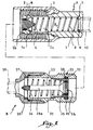
- the circuit breaker for hydraulic installation shown in Figures 1 to 5 comprises a male element A and a female element B provided both in tubular form.
- the male member A is formed with a tip 1 around which is arranged a nut 2 provided with an internal thread 3.
- the connector 1 includes a valve 4 intended to abut against a tapered surface 1a of the end 1 b of the tip 1.
- a ring 8, toroidal or substantially toroidal, is disposed in a peripheral housing 9 of the valve 4 to bear against the end 1b of the nozzle 1 in the closed position or locking of the circuit breaker, such as as shown in Figure 1.
- a conduit 10 connected to the nozzle 1 is connected to a pressurized source of fluid such as water, so that a pressure P 0 prevails inside the nozzle 1.
- the female element B is, in turn, connected to a conduit 20 connected to a device for using the fluid under pressure from the conduit 10.
- the female element B comprises a sleeve 21 provided with an external thread 22 provided to cooperate with the internal thread 3 the nut 2.
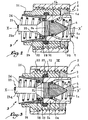
- screwing elements 2 and 21 together has effect of penetrating the tip 1 inside the sleeve 21 in the sequence shown in Figures 2 to 5.
- the sleeve 21 contains a piston 23 whose head 24 has a cross section substantially identical to that of the valve 4, so that it can penetrate inside the end 1b of the tip.1, pushing the valve 4 against the force exerted by the pressure P 0 and the spring 5.
- XX ' is the axis of displacement of the elements 4, 23 and 24 relative to the tip 1.
- a countervalve 25 is disposed around the head 24 of the piston 23. This counter-valve undergoes a thrust force in direction of the outlet of the sleeve 21, this effort being due to a resilient return spring 26 resting against a washer 27 immobilized between the sleeve 21 and an end fitting 20 ' duct 20 screwed onto the sleeve 21.
- a seal 28, toric or generally toric, is disposed in a housing 29 formed in the counter-valve 25 so as to bear against the outer radial surface of the head 24 of the piston 23 in the position of FIG.
- An O-ring 32 is provided close to the outlet of the sleeve 21 in a housing 33, so as to come into support against the outer radial surface of the tip 1 when elements A and B are coupled.
- the screwing of the nut 2 on the sleeve 21 has the effect of moving the tip 1 inside the sleeve 21 by pushing the countervalve 25, while the piston 23 can be held stationary relative to the tip 21 to which it is kinematically connected by a rod 23 integral with a washer 27.
- the head 24 of piston 23 enters the interior of the end 1b of the connector 1 as and as endpiece penetrates inside the sleeve 21.
- the housing 9 is connected downstream of the valve 4, that is to say to the front face of the head 24 of the piston 23, by at least one channel 40, two channels being represented on the figures.
- Each channel 40 connects the interior volume of the housing 9 at a peripheral zone 41 defined between the outer surface of the valve 4 and the inner surface 1a of the connector 1, that is to say radially around the valve 4.
- the preferential circuit is constituted by to the functional game between pieces 4 and 24 on the one hand, 4 and 1 on the other hand.
- it can be provided notches radial, not shown, to the right of the channels 40 on the face downstream of the valve 4 or on the front face of the head 24, these notches favoring the setting in communication of the channels 40 and from zone 41.
- the circuit formed between the channels 40 and the zone 41 is also preferred in that it is shorter than the circuit formed between the elements 24 and 1. Indeed, the bearing surface between the head 24 and the end 1b the sleeve 1, as shown in Figure 4, is substantially larger than the bearing surface between the valve 4 and the head 24, so that, with equivalent functional clearance, the fluid would tend to move towards the zone 41 rather than towards the interior volume of the sleeve 21.
- the outer peripheral surface of the head 24 may be provided with annular grooves 42 intended to form disturbances in the flow of fluid between elements 24 and 1b , so as to increase the pressure drops.
- the preferential character of the fluid flow circuit between the channels 40 and the zone 41 is intended to ensure that the pressure P 0 , or a pressure substantially equivalent to this pressure, serves as a back pressure in the zone 41 to exert on the joint 8 a force tending to bring it towards the interior of the housing 9.
- the channels 40 of the preferential circuit are not not put under pressure as long as the seal 8 remains in place in the housing 9, as shown in FIG. displacement of the seal 8 towards the outside of the housing 9 has for effect of opening the input channels 40 which are then put in pressure, this putting into pressure resulting in a setting corresponding pressure in zone 41, which has the effect of create the effort represented by the arrow F and fold down the seal 8 towards the interior of the dwelling 9.
- it is the deformation or the displacement of the gasket 8 towards the outside of housing 9 which generates the effort of putting back in place of this seal.
- the housing 9 is also connected to the main internal volume 1 c of the nozzle 1 through several channels 43, two of which are visible in the figures, these channels allowing a flow of fluid towards the channels 40 independently of the position of the seal 8 inside the dwelling 9.
- the channels 43 are advantageously arranged opposite channels 40, so that channels 40 and 43 can be made in a drilling operation, parallel to the axis XX '.
- channels 40 and 43 are regularly distributed around axis XX 'so that the zone of backpressure 41 is fed symmetrically around the axis XX '.
- the force exerted on the joint 8 thanks to the backpressure prevailing in this area is also regularly distributed around this axis.
- the number of channels 40 and 43 is included between 3 and 64, preferably between 3 and 12.
- the number of channels 40 and 43 could be more important.
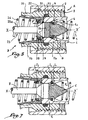
- the remainder of the nut screw movement 2 of the sleeve 21 has the effect of moving the head 24 of the piston 23 inwardly of the connector 1, so that given the flared character of the surface 1a , the fluid flow circuit between the parts 1 and 24 is increased in its section to the point that the pressure losses exerted on the fluid are very substantially decreased.
- the invention has been presented with the male element A connected to a source of pressure. It can also be applied to the case where the female element B is connected to a source of pressure then that the male element A is connected to a device or a fluid consumption system as shown in FIG. figure 6.
- channels 60 and 63 are respectively provided in downstream and upstream of the seal 28, so as to allow feeding a back pressure zone 61 formed radially around of the head 24 of the piston 23.
- the seal 28 Under the effect of the pressure P ' 0 prevailing in the sleeve 21, the seal 28 is moved to a zone of lower pressure, that is to say in the direction of the head 24 of the piston 23.
- the prevailing back pressure in the zone 61 exerts on the seal 28 a force represented by the arrow F in FIG. 6, this force tending to push this seal towards the interior of the housing 29.
- channels 60 and 63 are regularly distributed around the axis XX '. Obstacles can be provided on the outer radial surface of the valve 4 to increase the losses during the transitional phases of opening of the valve to create a preferential flow path between housing 29 and the backpressure zone, through the channels 60.
- annular grooves may also be provided on the inner surface of the end 1b of the element 1. In all cases, other types of obstacles intended to increase the pressure drops can be envisaged.
- the invention has been described with reference to a circuit breaker for a fluid installation not or little compressible. She remains applicable for other types of installations, especially adapted to compressible fluids such as gases.
- the invention can also be implemented with fluids two phases, depending on the conditions of use, in liquid or gaseous form, and in particular with a heat transfer fluid such as freon.
Landscapes
- Engineering & Computer Science (AREA)
- General Engineering & Computer Science (AREA)
- Mechanical Engineering (AREA)
- Quick-Acting Or Multi-Walled Pipe Joints (AREA)
- Check Valves (AREA)
- Percussive Tools And Related Accessories (AREA)
Claims (11)
- Abschaltgerät für eine Anlage zur Handhabung von unter Druck stehenden Flüssigkeiten mit einem Innenventil (4), wobei mindestens eine Dichtung (8) mit im Wesentlichen torischer Form in einem Aufnahmeraum (9) um das Ventil herum angeordnet ist,
dadurch gekennzeichnet, dass der Aufnahmeraum durch mindestens einen Zirkulationskanal (40) für Flüssigkeit mit einer Gegendruckzone (41) verbunden ist, die stromabwärts zur Dichtung (8) um das Ventil (4) herum ausgebildet ist, wobei die Gegendruckzone (41) bei einer Übergangsphase der Öffnung des Ventils über den Kanal (40) in dem Fall einer Verschiebung der Dichtung (8) aus dem Aufnahmeraum (9) heraus unter Druck gesetzt wird, wobei das Unterdrucksetzen (P0) der Gegendruckzone durch die Flüssigkeit über den Kanal (40) eine Kraft (F) ausübt, die die Dichtung in das Innere des Aufnahmeraums zurückdrängt. - Abschaltgerät für eine Anlage zur Handhabung von unter Druck stehenden Flüssigkeiten mit einem Innenventil (4) und einem Betätigungsorgan (23, 24) des Ventils, wobei mindestens eine Dichtung (28) mit im Wesentlichen torischer Form in einem Aufnahmeraum (29) um das Betätigungsorgan (23, 24) herum angeordnet ist, dadurch gekennzeichnet, dass der Aufnahmeraum durch mindestens einen Zirkulationskanal (60) für Flüssigkeit mit einer Gegendruckzone (61) verbunden ist, die stromabwärts zur Dichtung (28) um das Betätigungsorgan (23, 24) herum ausgebildet ist, wobei die Gegendruckzone (61) bei einer Übergangsphase der Öffnung des Abschaltgerätes um das Betätigungsorgan herum über den Kanal (60) in dem Fall einer Verschiebung der Dichtung (28) aus dem Aufnahmeraum (29) heraus unter Druck gesetzt wird, wobei das Unterdrucksetzen (P0) der Gegendruckzone durch die Flüssigkeit über den Kanal (60) eine Kraft (F) ausübt, die die Dichtung in das Innere des Aufnahmeraums zurückdrängt.
- Abschaltgerät nach einem der Ansprüche 1 oder 2, dadurch gekennzeichnet, dass bei einer Übergangsphase der Öffnung des Ventils ein bevorzugter Strömungskreis der Flüssigkeit zwischen dem Aufnahmeraum (9, 29) und der Gegendruckzone (41, 61) über den Kanal (40, 60) vorgesehen ist.
- Abschaltgerät nach Anspruch 3, dadurch gekennzeichnet, dass der bevorzugte Stromkreis eine solche Geometrie aufweist, dass die Druckverluste, die er auf die Flüssigkeit während des Fließens und bei der Übergangsphase des Öffnens des Ventils (4) bewirkt, geringer sind als die Druckverluste, die der Flüssigkeit durch einen Hauptströmungskreis der Flüssigkeit mitgeteilt werden, der zwischen dem Ventil (4) - beziehungsweise dem Betätigungsorgan (23, 24) - und einem Dichtungskörper (16) definiert ist.
- Abschaltgerät nach Anspruch 4, dadurch gekennzeichnet, dass der Hauptströmungskreis der Flüssigkeit mit Hindernissen (42) versehen ist, die geeignet sind, die der Flüssigkeit mitgeteilten Druckverluste zu erhöhen.
- Abschaltgerät nach Anspruch 5, dadurch gekennzeichnet, dass die Hindernisse durch Ringnuten gebildet sind, die an mindestens einer der Flächen gegenüberstehend zum Betätigungsorgan (24), zum Ventil (4) oder zum Dichtungskörper (1b) angeordnet sind, die stromabwärts zur Dichtung gelegen ist.
- Abschaltgerät nach einem der Ansprüche 3 bis 6, dadurch gekennzeichnet, dass bei einer Übergangsphase der Öffnung des Ventils (4) der Durchflussquerschnitt des bevorzugten Strömungskreises größer ist als der korrespondierende Durchflussquerschnitt eines Hauptströmungskreises der Flüssigkeit, der zwischen dem Ventil (4) - beziehungsweise dem Betätigungsorgan (23, 24) - und einem Dichtungskörper (1b) definiert ist.
- Abschaltgerät nach einem der Ansprüche 3 bis 7, dadurch gekennzeichnet, dass die Gesamtlänge des bevorzugten Strömungskreises kleiner ist als die korrespondierende Länge eines Hauptströmungskreises der Flüssigkeit, der zwischen dem Ventil (4) - beziehungsweise dem Betätigungsorgan (23, 24) - und einem Dichtungskörper (1b) definiert ist.
- Abschaltgerät nach einem der vorhergehenden Ansprüche, dadurch gekennzeichnet, dass der Aufnahmeraum (9, 29) mit der Gegendruckzone (41, 61) durch mehrere Zirkulationskanäle (40, 60) für Flüssigkeit verbunden ist, die um eine Verschiebungsachse (XX') des Ventils (4) herum verteilt sind.
- Abschaltgerät nach einen der vorhergehenden Ansprüche, dadurch gekennzeichnet, dass der Aufnahmeraum (9, 29) durch mindestens einen Flüssigkeitskanal (13, 63) mit mindestens einer unter Druck stehenden Flüssigkeitszone (1c) verbunden ist, die stromaufwärts zur Dichtung (8, 28) gebildet ist.
- Abschaltgerät nach Anspruch 10, dadurch gekennzeichnet, dass der Aufnahmeraum (9, 29) mit der unter Druck stehenden Flüssigkeitszone (1c) durch mehrere Flüssigkeitskanäle (43, 63) verbunden ist, die um die Verschiebungsachse (XX') des Ventils (4) herum verteilt sind.
Applications Claiming Priority (2)
| Application Number | Priority Date | Filing Date | Title |
|---|---|---|---|
| FR9808476 | 1998-06-30 | ||
| FR9808476A FR2780483B1 (fr) | 1998-06-30 | 1998-06-30 | Coupe-circuit pour installation de manutention de fluide sous pression |
Publications (2)
| Publication Number | Publication Date |
|---|---|
| EP0969239A1 EP0969239A1 (de) | 2000-01-05 |
| EP0969239B1 true EP0969239B1 (de) | 2004-11-17 |
Family
ID=9528181
Family Applications (1)
| Application Number | Title | Priority Date | Filing Date |
|---|---|---|---|
| EP99420143A Expired - Lifetime EP0969239B1 (de) | 1998-06-30 | 1999-06-25 | Abschaltgerät für unter Druck stehende Flüssigkeitshandhabungs-Anlage |
Country Status (6)
| Country | Link |
|---|---|
| US (1) | US6176263B1 (de) |
| EP (1) | EP0969239B1 (de) |
| JP (1) | JP2000039090A (de) |
| DE (1) | DE69921897T2 (de) |
| ES (1) | ES2232095T3 (de) |
| FR (1) | FR2780483B1 (de) |
Families Citing this family (19)
| Publication number | Priority date | Publication date | Assignee | Title |
|---|---|---|---|---|
| US6488043B2 (en) * | 2001-04-25 | 2002-12-03 | Gaymar Industries, Inc. | Valve system |
| US6905143B2 (en) | 2002-03-22 | 2005-06-14 | Itt Manufacturing Enterprises, Inc. | Fluid conduit quick connector and stuffer pack |
| US8113547B2 (en) * | 2002-03-22 | 2012-02-14 | Cooper Standard Automotive Inc. | Snap mount fluid quick connector |
| US6845965B2 (en) * | 2002-04-18 | 2005-01-25 | Teleflex Gpi Control Systems L.P. | Pressurized valve seal |
| US6802491B1 (en) | 2002-04-30 | 2004-10-12 | Itt Manufacturing Enterprises, Inc. | Fluid shut off valve cartridge with quick connection |
| JP2004324767A (ja) * | 2003-04-24 | 2004-11-18 | Nitto Kohki Co Ltd | 管継手のバルブ |
| FR2865790B1 (fr) | 2004-02-02 | 2007-07-13 | Staubli Sa Ets | Element male ou femelle de raccord rapide et raccord rapide comprenant un tel element |
| JP2006064083A (ja) * | 2004-08-27 | 2006-03-09 | Nitto Kohki Co Ltd | 継手部材 |
| JP5430104B2 (ja) * | 2008-09-11 | 2014-02-26 | 株式会社ブリヂストン | バルブ付き管継手 |
| US9739367B2 (en) | 2011-07-14 | 2017-08-22 | Oetiker Ny, Inc. | Transmission anti-leak valve |
| US20130037141A1 (en) * | 2011-07-14 | 2013-02-14 | Jiffy-Tite Company, Inc. | Transmission anti-leak valve |
| US9737980B2 (en) * | 2013-03-13 | 2017-08-22 | Eaton Corporation | Fluid filter installation tool |
| US11067210B2 (en) | 2013-03-15 | 2021-07-20 | Colder Products Company | Low-spill coupling assembly |
| WO2014143809A1 (en) * | 2013-03-15 | 2014-09-18 | Colder Products Company | Low-spill coupling assembly |
| USD830524S1 (en) | 2014-03-14 | 2018-10-09 | Colder Products Company | Coupling |
| US10941892B2 (en) * | 2017-02-17 | 2021-03-09 | Hewlett Packard Enterprise Development Lp | Valved connector |
| CN110500463B (zh) | 2019-07-17 | 2021-08-20 | 华为技术有限公司 | 一种接头、冷却系统和计算机装置 |
| US11619332B2 (en) * | 2020-02-13 | 2023-04-04 | Eaton Intelligent Power Limited | Quick disconnect fitting |
| GB2606388B (en) * | 2021-05-06 | 2024-02-28 | Alpha Process Controls International Ltd | Coupling |
Family Cites Families (3)
| Publication number | Priority date | Publication date | Assignee | Title |
|---|---|---|---|---|
| GB581087A (en) * | 1944-06-12 | 1946-10-01 | Automotive Prod Co Ltd | Improvements in or relating to pipe couplings |
| FR1039178A (fr) * | 1951-06-29 | 1953-10-05 | Perfectionnement aux soupapes automatiques | |
| US5771927A (en) * | 1996-10-24 | 1998-06-30 | Kongsberg Offshore A.S. | Undersea hydraulic connector with equalization channel |
-
1998
- 1998-06-30 FR FR9808476A patent/FR2780483B1/fr not_active Expired - Fee Related
-
1999
- 1999-06-07 US US09/327,195 patent/US6176263B1/en not_active Expired - Lifetime
- 1999-06-25 ES ES99420143T patent/ES2232095T3/es not_active Expired - Lifetime
- 1999-06-25 EP EP99420143A patent/EP0969239B1/de not_active Expired - Lifetime
- 1999-06-25 DE DE69921897T patent/DE69921897T2/de not_active Expired - Lifetime
- 1999-06-29 JP JP11184189A patent/JP2000039090A/ja active Pending
Also Published As
| Publication number | Publication date |
|---|---|
| ES2232095T3 (es) | 2005-05-16 |
| FR2780483B1 (fr) | 2000-08-25 |
| JP2000039090A (ja) | 2000-02-08 |
| DE69921897T2 (de) | 2005-11-24 |
| US6176263B1 (en) | 2001-01-23 |
| DE69921897D1 (de) | 2004-12-23 |
| EP0969239A1 (de) | 2000-01-05 |
| FR2780483A1 (fr) | 1999-12-31 |
Similar Documents
| Publication | Publication Date | Title |
|---|---|---|
| EP0969239B1 (de) | Abschaltgerät für unter Druck stehende Flüssigkeitshandhabungs-Anlage | |
| EP3298243B1 (de) | Turbinenmotoreinheit zum schmieren einer lagerhalterung | |
| EP1526318B1 (de) | Schnellkupplung für die lösbare Verbindung zweier Leitungen und Verwendung einer solchen Kupplung | |
| EP2020555B1 (de) | Schnellkupplungselement und Schnellkupplung, die ein solches Element beinhaltet | |
| EP0432013B1 (de) | Rohrverbindung mit einer Vorrichtung zur Ableitung von Lecken | |
| FR2963062A1 (fr) | Assemblage entre un tourillon d'arbre de compresseur et un pignon conique pour l'entrainement d'un boitier d'accessoires d'une turbomachine | |
| FR2817017A1 (fr) | Refroidissement integral des injecteurs de decollage d'une chambre de combustion a deux tetes | |
| EP1106212A1 (de) | Feuerlöschdüse | |
| EP1085245B1 (de) | Verbindungsmittel für Anschliessen eines Rohres an röhrenförmigen Körper | |
| EP0900966B1 (de) | Sicherheits-Abschaltgerät für Flüssigkeitshandhabungs-Anlage | |
| EP0359659A1 (de) | Wellenkupplung in einer Lagerstütze einer Turbomaschine und Verfahren zur Entkupplung | |
| FR2901340A1 (fr) | Agencement de distributeur hydraulique sous forme de cartouche | |
| EP4010563B1 (de) | Prallkühlvorrichtung für ein turbomaschinen-aussengehäuse und turbomaschine mit entsprechender vorrichtung | |
| FR2582378A1 (fr) | Perfectionnement aux coupleurs a clapets visant a faciliter le retour des billes de verrouillage en position de verrouillage | |
| EP4308793A1 (de) | Lüftermodul mit ölübertragungsvorrichtung | |
| FR3018336A1 (fr) | Dispositif de connexion d'une conduite amovible et canalisation pourvue d'un tel dispositif | |
| FR2666116A1 (fr) | Vanne de securite de l'espace annulaire et procede pour commander l'ecoulement de fluides entre des conduits tubulaires exterieur et interieur. | |
| WO2016193596A1 (fr) | Dispositif de refroidissement d'un palier a roulement pour une turbomachine | |
| EP4584520A1 (de) | Inline-dichtung mit grossem durchmesser mit einer dichtungsplatte | |
| FR2492022A1 (fr) | Dispositif d'accouplement rigide monte sous pression de fluide | |
| EP1090245A1 (de) | Anordnungsverfahren zum verbinden einer armatur mit einem rohrelement und ein neuer typ kupplung zur duerchführung des verfahrens | |
| EP4090833B1 (de) | Anordnung für einen turbinenmotor | |
| FR2961566A1 (fr) | Actionneur a verin d'un organe mobile dans une turbomachine | |
| EP0034101B1 (de) | Abnehmbare Verbindung, insbesondere zum Verbinden zweier Röhren oder Leitungen | |
| FR2901313A1 (fr) | Dispositif de degazage pour une turbomachine |
Legal Events
| Date | Code | Title | Description |
|---|---|---|---|
| PUAI | Public reference made under article 153(3) epc to a published international application that has entered the european phase |
Free format text: ORIGINAL CODE: 0009012 |
|
| AK | Designated contracting states |
Kind code of ref document: A1 Designated state(s): CH DE ES FR GB IT LI SE |
|
| AX | Request for extension of the european patent |
Free format text: AL;LT;LV;MK;RO;SI |
|
| 17P | Request for examination filed |
Effective date: 20000204 |
|
| AKX | Designation fees paid |
Free format text: CH DE ES FR GB IT LI SE |
|
| 17Q | First examination report despatched |
Effective date: 20020211 |
|
| GRAP | Despatch of communication of intention to grant a patent |
Free format text: ORIGINAL CODE: EPIDOSNIGR1 |
|
| GRAS | Grant fee paid |
Free format text: ORIGINAL CODE: EPIDOSNIGR3 |
|
| GRAA | (expected) grant |
Free format text: ORIGINAL CODE: 0009210 |
|
| AK | Designated contracting states |
Kind code of ref document: B1 Designated state(s): CH DE ES FR GB IT LI SE |
|
| REG | Reference to a national code |
Ref country code: GB Ref legal event code: FG4D Free format text: NOT ENGLISH |
|
| REG | Reference to a national code |
Ref country code: CH Ref legal event code: EP |
|
| GBT | Gb: translation of ep patent filed (gb section 77(6)(a)/1977) |
Effective date: 20041105 |
|
| REF | Corresponds to: |
Ref document number: 69921897 Country of ref document: DE Date of ref document: 20041223 Kind code of ref document: P |
|
| REG | Reference to a national code |
Ref country code: SE Ref legal event code: TRGR |
|
| REG | Reference to a national code |
Ref country code: ES Ref legal event code: FG2A Ref document number: 2232095 Country of ref document: ES Kind code of ref document: T3 |
|
| PLBE | No opposition filed within time limit |
Free format text: ORIGINAL CODE: 0009261 |
|
| STAA | Information on the status of an ep patent application or granted ep patent |
Free format text: STATUS: NO OPPOSITION FILED WITHIN TIME LIMIT |
|
| 26N | No opposition filed |
Effective date: 20050818 |
|
| REG | Reference to a national code |
Ref country code: FR Ref legal event code: PLFP Year of fee payment: 18 |
|
| REG | Reference to a national code |
Ref country code: FR Ref legal event code: PLFP Year of fee payment: 19 |
|
| REG | Reference to a national code |
Ref country code: FR Ref legal event code: PLFP Year of fee payment: 20 |
|
| PGFP | Annual fee paid to national office [announced via postgrant information from national office to epo] |
Ref country code: FR Payment date: 20180626 Year of fee payment: 20 |
|
| PGFP | Annual fee paid to national office [announced via postgrant information from national office to epo] |
Ref country code: SE Payment date: 20180627 Year of fee payment: 20 |
|
| PGFP | Annual fee paid to national office [announced via postgrant information from national office to epo] |
Ref country code: GB Payment date: 20180627 Year of fee payment: 20 Ref country code: ES Payment date: 20180702 Year of fee payment: 20 Ref country code: DE Payment date: 20180627 Year of fee payment: 20 Ref country code: IT Payment date: 20180621 Year of fee payment: 20 |
|
| PGFP | Annual fee paid to national office [announced via postgrant information from national office to epo] |
Ref country code: CH Payment date: 20180704 Year of fee payment: 20 |
|
| REG | Reference to a national code |
Ref country code: DE Ref legal event code: R071 Ref document number: 69921897 Country of ref document: DE |
|
| REG | Reference to a national code |
Ref country code: CH Ref legal event code: PL |
|
| REG | Reference to a national code |
Ref country code: GB Ref legal event code: PE20 Expiry date: 20190624 |
|
| REG | Reference to a national code |
Ref country code: SE Ref legal event code: EUG |
|
| PG25 | Lapsed in a contracting state [announced via postgrant information from national office to epo] |
Ref country code: GB Free format text: LAPSE BECAUSE OF EXPIRATION OF PROTECTION Effective date: 20190624 |
|
| REG | Reference to a national code |
Ref country code: ES Ref legal event code: FD2A Effective date: 20201202 |
|
| PG25 | Lapsed in a contracting state [announced via postgrant information from national office to epo] |
Ref country code: ES Free format text: LAPSE BECAUSE OF EXPIRATION OF PROTECTION Effective date: 20190626 |