EP1526318B1 - Schnellkupplung für die lösbare Verbindung zweier Leitungen und Verwendung einer solchen Kupplung - Google Patents
Schnellkupplung für die lösbare Verbindung zweier Leitungen und Verwendung einer solchen Kupplung Download PDFInfo
- Publication number
- EP1526318B1 EP1526318B1 EP20040356167 EP04356167A EP1526318B1 EP 1526318 B1 EP1526318 B1 EP 1526318B1 EP 20040356167 EP20040356167 EP 20040356167 EP 04356167 A EP04356167 A EP 04356167A EP 1526318 B1 EP1526318 B1 EP 1526318B1
- Authority
- EP
- European Patent Office
- Prior art keywords
- male
- elements
- female
- valve
- connection according
- Prior art date
- Legal status (The legal status is an assumption and is not a legal conclusion. Google has not performed a legal analysis and makes no representation as to the accuracy of the status listed.)
- Expired - Lifetime
Links
Images

Classifications
-
- F—MECHANICAL ENGINEERING; LIGHTING; HEATING; WEAPONS; BLASTING
- F16—ENGINEERING ELEMENTS AND UNITS; GENERAL MEASURES FOR PRODUCING AND MAINTAINING EFFECTIVE FUNCTIONING OF MACHINES OR INSTALLATIONS; THERMAL INSULATION IN GENERAL
- F16L—PIPES; JOINTS OR FITTINGS FOR PIPES; SUPPORTS FOR PIPES, CABLES OR PROTECTIVE TUBING; MEANS FOR THERMAL INSULATION IN GENERAL
- F16L37/00—Couplings of the quick-acting type
- F16L37/28—Couplings of the quick-acting type with fluid cut-off means
- F16L37/30—Couplings of the quick-acting type with fluid cut-off means with fluid cut-off means in each of two pipe-end fittings
- F16L37/32—Couplings of the quick-acting type with fluid cut-off means with fluid cut-off means in each of two pipe-end fittings at least one of two lift valves being opened automatically when the coupling is applied
- F16L37/34—Couplings of the quick-acting type with fluid cut-off means with fluid cut-off means in each of two pipe-end fittings at least one of two lift valves being opened automatically when the coupling is applied at least one of the lift valves being of the sleeve type, i.e. a sleeve being telescoped over an inner cylindrical wall
-
- F—MECHANICAL ENGINEERING; LIGHTING; HEATING; WEAPONS; BLASTING
- F16—ENGINEERING ELEMENTS AND UNITS; GENERAL MEASURES FOR PRODUCING AND MAINTAINING EFFECTIVE FUNCTIONING OF MACHINES OR INSTALLATIONS; THERMAL INSULATION IN GENERAL
- F16L—PIPES; JOINTS OR FITTINGS FOR PIPES; SUPPORTS FOR PIPES, CABLES OR PROTECTIVE TUBING; MEANS FOR THERMAL INSULATION IN GENERAL
- F16L37/00—Couplings of the quick-acting type
- F16L37/08—Couplings of the quick-acting type in which the connection between abutting or axially overlapping ends is maintained by locking members
- F16L37/084—Couplings of the quick-acting type in which the connection between abutting or axially overlapping ends is maintained by locking members combined with automatic locking
- F16L37/0841—Couplings of the quick-acting type in which the connection between abutting or axially overlapping ends is maintained by locking members combined with automatic locking by means of a transversally slidable locking member surrounding the tube
-
- Y—GENERAL TAGGING OF NEW TECHNOLOGICAL DEVELOPMENTS; GENERAL TAGGING OF CROSS-SECTIONAL TECHNOLOGIES SPANNING OVER SEVERAL SECTIONS OF THE IPC; TECHNICAL SUBJECTS COVERED BY FORMER USPC CROSS-REFERENCE ART COLLECTIONS [XRACs] AND DIGESTS
- Y10—TECHNICAL SUBJECTS COVERED BY FORMER USPC
- Y10T—TECHNICAL SUBJECTS COVERED BY FORMER US CLASSIFICATION
- Y10T137/00—Fluid handling
- Y10T137/8593—Systems
- Y10T137/87917—Flow path with serial valves and/or closures
- Y10T137/87925—Separable flow path section, valve or closure in each
- Y10T137/87941—Each valve and/or closure operated by coupling motion
- Y10T137/87949—Linear motion of flow path sections operates both
-
- Y—GENERAL TAGGING OF NEW TECHNOLOGICAL DEVELOPMENTS; GENERAL TAGGING OF CROSS-SECTIONAL TECHNOLOGIES SPANNING OVER SEVERAL SECTIONS OF THE IPC; TECHNICAL SUBJECTS COVERED BY FORMER USPC CROSS-REFERENCE ART COLLECTIONS [XRACs] AND DIGESTS
- Y10—TECHNICAL SUBJECTS COVERED BY FORMER USPC
- Y10T—TECHNICAL SUBJECTS COVERED BY FORMER US CLASSIFICATION
- Y10T137/00—Fluid handling
- Y10T137/8593—Systems
- Y10T137/87917—Flow path with serial valves and/or closures
- Y10T137/87925—Separable flow path section, valve or closure in each
- Y10T137/87965—Valve- or closure-operated by coupling motion
Definitions
- the invention relates to a quick coupling for the removable connection of pressurized fluid lines, as well as to the use of such a connection.
- US Patent 5,494,074 discloses a connector whose male and female elements are each provided with a valve whose protruding parts abut one on the other, so that a dead volume is created between the valves, which, at the opening of the fitting, induces leaks.
- FR-A-2,063,800 discloses a quick coupling which, in the embodiment of Figures 4 and 5, comprises male and female elements equipped with valves, while a tubular element interposed between these valves defines a dead volume generating dripping or leakage, in particular to the opening of the fitting.
- the U-shaped resilient blade used for locking in the fitting configuration of the coupling is unreliable.
- the invention intends to remedy more particularly by proposing a new quick coupling of the double-shutter type whose operation is facilitated.
- the invention relates to a quick coupling for the detachable joining of two pipes traversed by a pressurized fluid, this connection consisting of two elements, male and female, capable of being axially engaged one inside the other and each comprising a body inside which is movable a valve, a fixed part of each element being able to move the movable valve of the other element during their fitting.
- the female element is provided with a member in which is adapted to be introduced a portion of the male element and which is movable in translation in a radial direction relative to the axis of fitting male and female elements, between a first position in which this member allows the separation of these elements, and a second position where this member opposes withdrawal of the male element out of the female element, in that when the male and female elements are separated, their respective fixed parts and their respective movable valves define, respectively in the male element and in the female element, complementary volumes whose facing surfaces can be in surface support on one another and in that the aforementioned surfaces are flat and generally perpendicular to a longitudinal axis of the corresponding element and the fitting axis of said elements.
- the control of the coupling of the male and female elements can be carried out thanks to the movable member which moves transversely with respect to the direction of fitting.
- the invention takes the opposite view of a prejudice of the person skilled in the art who hitherto tended to consider that a double-shutter quick coupling required axisymmetric locking, as obtained with balls, except to risk a misalignment of the valves and fixed parts respectively provided on the male and female elements.
- the movable retaining member, which exerts on the male element a transverse force is not incompatible with the operation of the shutter valves.
- the invention makes it possible to minimize the dimensions of a coupling according to the invention insofar as a transverse displacement member requires less surface to be effectively operated by a user than a sleeve such as that known in the art. state of the art.
- the control force is exerted by the user on the control member perpendicular to the axis of the connection, so with little risk of sliding.
- connection of the invention thus makes it possible to effectively achieve a triple function of double sealing, ease of handling and sealing on connection / disconnection, by a structure that is both reliable, compact and economical.
- a connector may incorporate the features according to the dependent claims.
- the invention also relates to the use of at least one connector as previously described for the creation of a coolant circulation circuit for the cooling of electrical or electronic equipment.
- This use takes advantage of the fact that the constituent elements of a quick connector according to the invention can be of relatively modest dimensions and mounted in large numbers in an electrical cabinet.
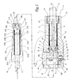
- connection shown in Figures 1 to 3 comprises a female element A and a male element or end B respectively connected to an upstream pipe C 1 and a downstream pipe C 2 .
- the upstream pipe C 1 is, itself, connected to a source of fluid under pressure not shown.
- the body 1 of the female element A is cylindrically conical outer shape with a circular base, centered on an axis X A -X ' A which is also the longitudinal axis of a duct 11 internal to the body 1 and in which is disposed a valve 2 movable along the axis X A -X ' A relative to the body 1.
- This valve 2 is intended to bear against a seat 12 formed by an internal frustoconical surface of the body 1.
- the valve 2 is subject to an elastic force F 1 exerted by a spring 3, this effort F 1 having a tendency to press against the seat 12.
- the valve 2 is centered on a head 41 of a pusher 4 whose stem 42, which is monobloc with the head 41, extends to the level of a rear portion 13 of the body 1 where it is held in position by three tabs 43 disposed substantially at 120 ° from each other about the axis X A -X ' A and wedged by a ring 14 screwed into the body 1 and on which is connected the pipe C 1 .
- the pusher 4 is centered on the axis X A- X ' A.
- Two O-rings 5 and 5 ' are respectively provided in a groove 15 provided on the internal radial surface of the body 1 and in a groove 45 provided on the outer radial surface of the head 41, these seals 5 and 5' being intended to provide a sealed contact with the valve 2 when the latter bears against the seat 12.
- the front portion 16 of the body 1 in which is provided an orifice 16a of introduction of the male element B.
- the surface 26 of the valve 2 and the surface 46 of the pusher 4 that are oriented toward the opening 16 a are globally co-planar in the configuration of the figure 1 and perpendicular to the axis X A -X ' A.
- the body 1 is provided with a housing 17 in which is disposed a spring-loaded button 7 by a F 2 force exerted by a spring 8 disposed between the button 7 and the bottom 17a 17.
- the displacement of the button 7 under the effect of the force F 2 is limited by a stop 18.
- the button 7 is movable in translation in the direction of the double arrow F 3 to the figure 1 , that is to say in a direction YY 'perpendicular to the axis X A -X' A. It defines a volume V 7 into which can be introduced a part of the male member B and extending from the orifice 16a to the vicinity of the surfaces 26 and 46.
- the button 7 is provided with a tooth 72.
- the male element B is provided with a cylindrical-conical body 101 inside which is formed a conduit 111 for circulating fluid under pressure, this conduit being in communication with the pipe C 2 .
- the body 101 is centered on an axis X B -X ' B which is also an axis of symmetry of the conduit 111 and which is intended to be aligned with the axis X A -X' A when the elements B and A are fitted. one in the other.
- a valve 102 loaded elastically by a force F 101 exerted by a spring 103 and tending to return the valve 102 to a closed configuration of the outlet of the conduit 111 on the front side of the element B , the valve 102 then resting on an internal frustoconical seat 112 formed by the body 101.
- the valve 102 is provided with a groove 125 in which is disposed a seal 105 intended to bear against the internal cylindrical surface of the front end of the body 101.
- the body 101 is provided with an outer radial flange 115 intended to interact with the tooth 72, in a known manner of FR-A-2 514 855 .
- the front face 126 of the valve 102 and the front face 116 of the body 101 are generally co-planar and perpendicular to the axis X B -X ' B in the configuration of the figure 1 .
- the face 115 has the flange 115 which is perpendicular to the axis X B -X 'B, is intended to abut against a face 72 a of the tooth 72 which is perpendicular to the axis X A -X' A as shown in figure 3 .
- the outer radial surface of the body 101 comprises three cylindrical surfaces 101 a, 101 b and 101 c whose diameter decreases towards the front of the body 1 and which are connected in pairs by frustoconical surfaces 101 d and 101 e.
- the male element B is intended to be introduced into the female element A in the direction of the arrow F 4 to the figure 2 .
- the body 1 is provided with a frustoconical surface 18 a which is formed in the vicinity of the stop 18 and for guiding the edge 114 to the center relative to the axis X a -X 'a and allow it to slide on a cylindrical surface of circular section 18b which is centered on the axis X a -X 'a, which extends the surface 18 a and whose radius is very slightly greater than that of the surface 113.
- the interaction of areas 18 a and 18 b on the one hand, 113 and 114 allows guidance of the front end of the element B when it is introduced into the element A.
- the circular surface 19 which defines the opening 16 has a radius substantially equal to that of the outer radial surface 115 b of the flange 115 and that of the surface 101b, which provides a guide the male member relative to the female member when the flange 115 passes through the opening 16a and when the body part 101 surrounded by the surface 101 b is in this opening, as shown in figure 3 .
- the movement of introduction of the element B into the element A has the effect of bringing surfaces 116 and 126 into surface abutment against the surfaces 26 and 46. If the pushing movement is continued to reach the configuration of the figure 3 , the valve 2 is pushed by the front face 116 of the body 101, while the valve 102 is pushed by the head 41 of the pusher 4, which allows to take off the valves 2 and 102 of their respective seats 12 and 112 and allows the flow of fluid under pressure, as represented by the arrows E at the figure 3 .
- the inclined surface 113 c of the flange 115 has pushed the tooth 72 against the force F 2 by sliding on its inclined surface 72 c and the flange 115 is locked behind the tooth 72, as shown on this same figure 3 .
- the front part of the body 101 comes, by its flat front face 116-126, in contact with the flat face 26-46 of the female element.
- the further fitting induces the passage of the flange 115 in the opening 16a and the sliding of the outer radial surface 115b of flange 115 on the lower portion of the surface 71.
- the body portion 101 bounded by the surface 101b enters the opening 16 a.
- the continuation of the fitting also induces a sliding of the surface 113 on the surface 18 b .
- the invention can be implemented for the constitution of a coolant circulation circuit in the direction of the arrow E to the figure 3 , or in the opposite direction, for the cooling of electrical or electronic equipment.
- the operating device formed by the button 7 can be of relatively modest size, as well as the bodies 1 and 101, which allows for connecting elements A and B of small size which can be produced in large numbers to create cooling systems for electrical cabinets, especially for computer servers.
- the invention has been shown when it is used in a connection where the valves and the associated fixed parts form, when the male and female elements are separated, plane faces 26-46 and 116-126 which are formed, for one, in the female element and, for the other, in the male element and are perpendicular to the axes X A- X ' A , X B- X' B and X-X '. This is particularly advantageous because the imprisonment of fluid is removed during the fitting.
Landscapes
- Engineering & Computer Science (AREA)
- General Engineering & Computer Science (AREA)
- Mechanical Engineering (AREA)
- Quick-Acting Or Multi-Walled Pipe Joints (AREA)
- Mutual Connection Of Rods And Tubes (AREA)
Claims (9)
- Schnellkupplung für die lösbare Verbindung von zwei Leitungen, die von einem unter Druck stehenden Fluid durchströmt werden, wobei die Kupplung ein Einsteckelement und ein Aufnahmeelement umfasst, die geeignet sind, axial ineinander gesteckt zu werden und die jeweils einen Körper umfassen, in dessen Innerem ein Ventil beweglich ist, wobei ein feststehendes Teil jedes Elements geeignet ist, das bewegliche Ventil des anderen Elements bei dem Ineinanderstecken der Elemente zu verschieben, dadurch gekennzeichnet, dass das Aufnahmeelement (A) mit einem Organ (7) versehen ist, in das ein Teil des Einsteckelements (B) eingesteckt werden kann und das translatorisch (F3) gemäß einer in Bezug auf die Einsteckachse (X-X') der Elemente radialen Richtung (Y-Y') zwischen einer ersten Position, in der das Organ die Trennung der Elemente zulässt, und einer zweiten Position, in der das Organ sich gegen ein Herausziehen des Einsteckelements aus dem Aufnahmeelement entgegenstellt, beweglich ist, dass, wenn die Elemente (A, B) getrennt sind, ihr jeweiliges feststehendes Teil (41, 101) und ihr bewegliches Ventil (2; 102) zusammen jeweils in dem Einsteckelement und in dem Aufnahmeelement komplementäre Volumen bilden, deren gegenüberstehende Flächen (26-46, 116-126) geeignet sind, in gegenseitige Flächenauflage zu kommen, und dass die Flächen (26-46, 116-126) eben und im Wesentlichen senkrecht zu einer Längsachse (X,-X'A, XB-X'B) des korrespondierenden Elements und zur Achse (X-X') des Ineinandersteckens der Elemente (A, B) sind.
- Kupplung nach Anspruch 1, dadurch gekennzeichnet, dass der Körper (1) des Aufnahmeelements (A) beidseitig des Organs (7) gemäß der Achse des Ineinandersteckens (X-X') der Elemente (A, B) zwei Zonen (18a, 18b, 19) der Führung bildet, die geeignet sind, gleichzeitig mit zwei Bereichen (101b, 113-115) des Einsteckelements (B) für die axiale relative Führung des Einsteckelements und des Aufnahmeelements bei ihrem Ineinanderstecken zusammenzuwirken.
- Kupplung nach einem der vorhergehenden Ansprüche, dadurch gekennzeichnet, dass das Ventil (2) des Aufnahmeelements (A) zu dem Kopf (41) eines Stößels (4) zentriert ist, der in Bezug auf den Körper (1) des Aufnahmeelements feststehend ist, während das Ventil (102) des Einsteckelements (B) in dem Körper (101) des Einsteckelements angeordnet ist, wobei eine vordere Fläche (116) des Körpers (101) des Einsteckelements geeignet ist, in Flächenauflage gegen eine Fläche (26) des Ventils (2) des Aufnahmeelements zu kommen, die zu der Öffnung (16a) des Einsteckens des Einsteckelements in das Aufnahmeelement gerichtet ist, wobei eine ebenfalls zu der Öffnung gerichtete Fläche (46) des Kopfes In Flächenauflage gegen eine vordere Fläche (126) des Ventils (102) des Einsteckelements kommt.
- Kupplung nach einem der vorhergehenden Ansprüche, dadurch gekennzeichnet, dass das Organ (7) in einem Aufnahmeraum (17) angeordnet ist, der in den Körper (1) des Aufnahmeelements (A) eingearbeitet ist und an der radialen Außenfläche des Körpers mündet.
- Kupplung nach einem der vorhergehenden Ansprüche, dadurch gekennzeichnet, dass das Einsteckelement (B) mit mindestens einem Relief (115) versehen ist, das geeignet ist, mit mindestens einem Relief (72) komplementärer Form, das von dem Organ (7) getragen wird, für die Blockierung der Elemente in gekuppelter Konfiguration zusammenzuarbeiten.
- Kupplung nach Anspruch 5, dadurch gekennzeichnet, dass das Relief des Einsteckelements (B) ein in Bezug auf den Hauptkörper (101) des Elements radialer äußerer Kragenring (115) ist.
- Kupplung nach einem der Ansprüche 5 oder 6, dadurch gekennzeichnet, dass das von dem Organ (7) getragene Relief ein Zahn (72) ist, der auf der radialen inneren Fläche (71) des Organs angebracht ist.
- Kupplung nach einem der vorhergehenden Ansprüche, dadurch gekennzeichnet, dass sie Mittel (8) zur elastischen Vorspannung (F2) des Organs (7) in die zweite Position umfasst.
- Verwendung von mindestens einer Kupplung (1-115) nach einem der vorhergehenden Ansprüche für die Erzeugung eines Kreises für die Zirkulation (E) eines Kühlmittels in Hinblick der Kühlung von elektrischen oder elektronischen Geräteanordnungen.
Applications Claiming Priority (2)
| Application Number | Priority Date | Filing Date | Title |
|---|---|---|---|
| FR0312188 | 2003-10-17 | ||
| FR0312188A FR2861159B1 (fr) | 2003-10-17 | 2003-10-17 | Raccord rapide pour la jonction amovible de deux canalisations et utilisation d'un tel raccord |
Publications (2)
| Publication Number | Publication Date |
|---|---|
| EP1526318A1 EP1526318A1 (de) | 2005-04-27 |
| EP1526318B1 true EP1526318B1 (de) | 2012-05-02 |
Family
ID=34385265
Family Applications (1)
| Application Number | Title | Priority Date | Filing Date |
|---|---|---|---|
| EP20040356167 Expired - Lifetime EP1526318B1 (de) | 2003-10-17 | 2004-10-15 | Schnellkupplung für die lösbare Verbindung zweier Leitungen und Verwendung einer solchen Kupplung |
Country Status (5)
| Country | Link |
|---|---|
| US (1) | US7044161B2 (de) |
| EP (1) | EP1526318B1 (de) |
| CN (1) | CN100489366C (de) |
| AT (1) | ATE556269T1 (de) |
| FR (1) | FR2861159B1 (de) |
Families Citing this family (41)
| Publication number | Priority date | Publication date | Assignee | Title |
|---|---|---|---|---|
| US20050082828A1 (en) | 2003-09-12 | 2005-04-21 | Wicks Jeffrey C. | Releasable connection assembly for joining tubing sections |
| US7448653B2 (en) | 2005-06-10 | 2008-11-11 | Value Plastics, Inc. | Female connector for releasable coupling with a male connector defining a fluid conduit |
| US7806139B2 (en) * | 2006-01-20 | 2010-10-05 | Value Plastics, Inc. | Fluid conduit coupling assembly having male and female couplers with integral valves |
| EP2024673B1 (de) * | 2006-05-15 | 2013-05-15 | Colder Products Company | Aseptische kupplungsvorrichtungen |
| USD654573S1 (en) | 2007-11-19 | 2012-02-21 | Value Plastics, Inc. | Female quick connect fitting |
| FR2928787B1 (fr) * | 2008-03-12 | 2012-06-22 | Staubli Sa Ets | Element femelle de connecteur et connecteur comprenant un tel element femelle |
| USD634840S1 (en) | 2008-07-03 | 2011-03-22 | Value Plastics, Inc. | Female body of connector for fluid tubing |
| USD630320S1 (en) | 2008-07-03 | 2011-01-04 | Value Plastics, Inc. | Connector for fluid tubing |
| USD629894S1 (en) | 2008-07-03 | 2010-12-28 | Value Plastics, Inc. | Male body of connector for fluid tubing |
| US8235426B2 (en) | 2008-07-03 | 2012-08-07 | Nordson Corporation | Latch assembly for joining two conduits |
| USD655393S1 (en) | 2009-06-23 | 2012-03-06 | Value Plastics, Inc. | Multi-port valve |
| US10711930B2 (en) | 2009-12-09 | 2020-07-14 | Nordson Corporation | Releasable connection assembly |
| USD649240S1 (en) | 2009-12-09 | 2011-11-22 | Value Plastics, Inc. | Male dual lumen bayonet connector |
| USD783815S1 (en) | 2009-12-09 | 2017-04-11 | General Electric Company | Male dual lumen bayonet connector |
| USD650478S1 (en) | 2009-12-23 | 2011-12-13 | Value Plastics, Inc. | Female dual lumen connector |
| US9388929B2 (en) | 2009-12-09 | 2016-07-12 | Nordson Corporation | Male bayonet connector |
| EP2516913B1 (de) | 2009-12-23 | 2014-09-17 | Nordson Corporation | Fluidverbinderverriegelungen mit profildurchführungen |
| CN102753876B (zh) | 2009-12-23 | 2015-07-22 | 诺信公司 | 具有一体式模制悬臂弹簧的按钮闩 |
| CN102478140B (zh) * | 2010-11-23 | 2013-10-16 | 英业达股份有限公司 | 快速接头 |
| CN102480902B (zh) * | 2010-11-23 | 2014-08-27 | 英业达股份有限公司 | 可调式冷却液快速接头 |
| USD652510S1 (en) | 2011-02-11 | 2012-01-17 | Value Plastics, Inc. | Connector for fluid tubing |
| USD663022S1 (en) | 2011-02-11 | 2012-07-03 | Nordson Corporation | Male body of connector for fluid tubing |
| USD652511S1 (en) | 2011-02-11 | 2012-01-17 | Value Plastics, Inc. | Female body of connector for fluid tubing |
| USD698440S1 (en) | 2011-07-29 | 2014-01-28 | Nordson Corporation | Connector for fluid tubing |
| USD699840S1 (en) | 2011-07-29 | 2014-02-18 | Nordson Corporation | Male body of connector for fluid tubing |
| USD699841S1 (en) | 2011-07-29 | 2014-02-18 | Nordson Corporation | Female body of connector for fluid tubing |
| USD709612S1 (en) | 2011-12-23 | 2014-07-22 | Nordson Corporation | Female dual lumen connector |
| US11067210B2 (en) | 2013-03-15 | 2021-07-20 | Colder Products Company | Low-spill coupling assembly |
| FR3014166B1 (fr) | 2013-12-02 | 2016-01-15 | Staubli Sa Ets | Raccord rapide pour la jonction amovible de deux canalisations |
| USD830523S1 (en) | 2014-03-14 | 2018-10-09 | Colder Products Company | Coupling |
| EP2955072A1 (de) * | 2014-06-13 | 2015-12-16 | J.Juan S.A. | Kupplungsanordnung für ein hydraulisches Fahrzeugbremssystem |
| DE102014118285A1 (de) * | 2014-12-10 | 2016-06-16 | Airbus Operations Gmbh | Drainiervorrichtung zum Drainieren einer Fluidleitung |
| EP3875824B1 (de) * | 2015-04-20 | 2024-10-30 | Colder Products Company | Aseptische einweg-flüssigkeitskupplungen |
| CN105782613B (zh) * | 2015-08-25 | 2018-02-16 | 杭州哈帝环保科技有限公司 | 液电一体快换接头 |
| USD838366S1 (en) | 2016-10-31 | 2019-01-15 | Nordson Corporation | Blood pressure connector |
| FR3084437B1 (fr) | 2018-07-24 | 2020-10-16 | Staubli Sa Ets | Raccord rapide pour la jonction amovible de deux canalisations parcourues par un fluide sous pression |
| FR3084436B1 (fr) | 2018-07-24 | 2021-01-15 | Staubli Sa Ets | Raccord rapide pour la jonction amovible de deux canalisations parcourues par un fluide sous pression |
| US11619334B2 (en) * | 2019-12-31 | 2023-04-04 | Colder Products Company | Fluid couplings |
| US12203579B2 (en) | 2020-11-16 | 2025-01-21 | Colder Products Company | Fluid handling couplings |
| JP7618801B2 (ja) * | 2020-11-16 | 2025-01-21 | コルダー プロダクツ カンパニー | 流体処理継手 |
| EP4437240A4 (de) * | 2021-11-23 | 2025-08-20 | Joseph A Manly | Energieübertragendes, durch bolzen und buchse lösbares befestigungssystem |
Family Cites Families (11)
| Publication number | Priority date | Publication date | Assignee | Title |
|---|---|---|---|---|
| US2637572A (en) * | 1950-07-14 | 1953-05-05 | Us Army | Self-sealing coupling |
| US2868563A (en) * | 1956-06-05 | 1959-01-13 | Wayne L Wood | Fluid line coupling device |
| FR1561337A (de) * | 1968-01-17 | 1969-03-28 | ||
| FR2063800A5 (de) * | 1969-10-31 | 1971-07-09 | Corobit Anstalt | |
| FR2514855A1 (fr) * | 1981-10-20 | 1983-04-22 | Staubli Sa Ets | Perfectionnements aux raccords rapides pour la jonction amovible des canalisations |
| US4613112A (en) * | 1985-07-19 | 1986-09-23 | Essex Industries, Inc. | Quick-disconnect fitting for gas line connection |
| JPH0618123Y2 (ja) * | 1989-11-11 | 1994-05-11 | 日東工器株式会社 | 管継手のソケット |
| US5143347A (en) * | 1992-01-14 | 1992-09-01 | Lee Yeong D | Revolvable quick coupling |
| US5316041A (en) * | 1992-10-27 | 1994-05-31 | Colder Product Company | Quick connection coupling valve assembly |
| JP2559233Y2 (ja) * | 1993-07-07 | 1998-01-14 | 日東工器株式会社 | 管継手 |
| FR2719105B1 (fr) * | 1994-04-21 | 1996-05-31 | Yto | Coupleur rapide pour conduit sous pression à désaccouplement contrôlé. |
-
2003
- 2003-10-17 FR FR0312188A patent/FR2861159B1/fr not_active Expired - Fee Related
-
2004
- 2004-10-08 US US10/959,990 patent/US7044161B2/en not_active Expired - Lifetime
- 2004-10-14 CN CNB2004100837510A patent/CN100489366C/zh not_active Expired - Fee Related
- 2004-10-15 AT AT04356167T patent/ATE556269T1/de active
- 2004-10-15 EP EP20040356167 patent/EP1526318B1/de not_active Expired - Lifetime
Also Published As
| Publication number | Publication date |
|---|---|
| FR2861159B1 (fr) | 2007-05-11 |
| CN100489366C (zh) | 2009-05-20 |
| EP1526318A1 (de) | 2005-04-27 |
| US7044161B2 (en) | 2006-05-16 |
| CN1609496A (zh) | 2005-04-27 |
| US20050081929A1 (en) | 2005-04-21 |
| ATE556269T1 (de) | 2012-05-15 |
| FR2861159A1 (fr) | 2005-04-22 |
Similar Documents
| Publication | Publication Date | Title |
|---|---|---|
| EP1526318B1 (de) | Schnellkupplung für die lösbare Verbindung zweier Leitungen und Verwendung einer solchen Kupplung | |
| EP1557599B1 (de) | Schnellkupplung und Verfahren zum Lösen der ineinander gesteckten Teile der Schnellkupplung | |
| EP1422462B1 (de) | Schnellkupplung mit einer integrierten Druckentlastungsvorrichtung | |
| EP1853842B1 (de) | Schnellkupplung zur verbindung zweier druckgasleitungen | |
| EP2439440B1 (de) | Anschlussvorrichtung mit Verriegelung durch Gewindegriffe, und Anschluss, der eine solche Vorrichtung enthält | |
| EP1308663B1 (de) | Schnellkupplung für die lösbare Verbindung zweier Rohrleitungen | |
| EP1135643B1 (de) | Kugelkupplung | |
| EP1333218B1 (de) | Schnellkupplung für die lösbare Verbindung zweier Rohrleitungen | |
| EP2278205B1 (de) | Kupplungsaufnahme und diese beinhaltende Schnellkupplung | |
| EP2306061B1 (de) | Schnellkupplungsmuffe und Schnellkupplung mit solcher Schnellkupplungsmuffe | |
| EP1219885A1 (de) | Steckdosenelement und Schnellkupplung und Vorrichtung die ein solches Element enthält | |
| EP1422461A1 (de) | Schnellkupplung zur trennbaren Verbindung von zwei Rohre | |
| EP3184870B1 (de) | Buchse eines schnellanschlusses, und eine solche buchse umfassender schnellanschluss | |
| FR2862369A1 (fr) | Element femelle de raccord et raccord rapide incorporant un tel element | |
| EP3599408B1 (de) | Schnellkupplung für die lösbare verbindung von zwei rohren, durch die eine flüssigkeit unter druck fliesst | |
| EP2778495A1 (de) | Aufnahmeelement und Anschlussstück zur Ausführung einer abnehmbaren Verbindung zwischen zwei Flüssigkeitskanalisationssystemen | |
| EP2878872A1 (de) | Schnellanschluss zur lösbaren verbindung von zwei rohren | |
| EP4421371A1 (de) | Schnellkupplungsbuchse und zugehörige schnellkupplung | |
| EP2587109B1 (de) | Anschlussvorrichtung | |
| FR2771472A1 (fr) | Raccord encliquetable notamment pour conduites de carburant | |
| WO2025153441A1 (fr) | Dispositif de couplage fluidique | |
| EP4497986A1 (de) | Verbindungselement und verfahren zur herstellung eines solchen verbindungselements | |
| FR2866409A3 (fr) | Raccord femelle pour conduite de fluide | |
| FR2790057A1 (fr) | Coupleur a billes | |
| FR3072155A3 (fr) | Element de raccord fluidique et raccord fluidique incorporant un tel element |
Legal Events
| Date | Code | Title | Description |
|---|---|---|---|
| PUAI | Public reference made under article 153(3) epc to a published international application that has entered the european phase |
Free format text: ORIGINAL CODE: 0009012 |
|
| AK | Designated contracting states |
Kind code of ref document: A1 Designated state(s): AT BE BG CH CY CZ DE DK EE ES FI FR GB GR HU IE IT LI LU MC NL PL PT RO SE SI SK TR |
|
| AX | Request for extension of the european patent |
Extension state: AL HR LT LV MK |
|
| 17P | Request for examination filed |
Effective date: 20050916 |
|
| AKX | Designation fees paid |
Designated state(s): AT BE BG CH CY CZ DE DK EE ES FI FR GB GR HU IE IT LI LU MC NL PL PT RO SE SI SK TR |
|
| 17Q | First examination report despatched |
Effective date: 20080211 |
|
| GRAP | Despatch of communication of intention to grant a patent |
Free format text: ORIGINAL CODE: EPIDOSNIGR1 |
|
| RIC1 | Information provided on ipc code assigned before grant |
Ipc: F16L 37/34 20060101ALI20111109BHEP Ipc: F16L 37/084 20060101AFI20111109BHEP |
|
| GRAS | Grant fee paid |
Free format text: ORIGINAL CODE: EPIDOSNIGR3 |
|
| GRAA | (expected) grant |
Free format text: ORIGINAL CODE: 0009210 |
|
| AK | Designated contracting states |
Kind code of ref document: B1 Designated state(s): AT BE BG CH CY CZ DE DK EE ES FI FR GB GR HU IE IT LI LU MC NL PL PT RO SE SI SK TR |
|
| REG | Reference to a national code |
Ref country code: GB Ref legal event code: FG4D Free format text: NOT ENGLISH |
|
| REG | Reference to a national code |
Ref country code: AT Ref legal event code: REF Ref document number: 556269 Country of ref document: AT Kind code of ref document: T Effective date: 20120515 Ref country code: CH Ref legal event code: EP |
|
| REG | Reference to a national code |
Ref country code: IE Ref legal event code: FG4D Free format text: LANGUAGE OF EP DOCUMENT: FRENCH |
|
| REG | Reference to a national code |
Ref country code: DE Ref legal event code: R096 Ref document number: 602004037591 Country of ref document: DE Effective date: 20120705 |
|
| REG | Reference to a national code |
Ref country code: NL Ref legal event code: VDEP Effective date: 20120502 |
|
| PG25 | Lapsed in a contracting state [announced via postgrant information from national office to epo] |
Ref country code: SE Free format text: LAPSE BECAUSE OF FAILURE TO SUBMIT A TRANSLATION OF THE DESCRIPTION OR TO PAY THE FEE WITHIN THE PRESCRIBED TIME-LIMIT Effective date: 20120502 Ref country code: PL Free format text: LAPSE BECAUSE OF FAILURE TO SUBMIT A TRANSLATION OF THE DESCRIPTION OR TO PAY THE FEE WITHIN THE PRESCRIBED TIME-LIMIT Effective date: 20120502 Ref country code: FI Free format text: LAPSE BECAUSE OF FAILURE TO SUBMIT A TRANSLATION OF THE DESCRIPTION OR TO PAY THE FEE WITHIN THE PRESCRIBED TIME-LIMIT Effective date: 20120502 Ref country code: CY Free format text: LAPSE BECAUSE OF FAILURE TO SUBMIT A TRANSLATION OF THE DESCRIPTION OR TO PAY THE FEE WITHIN THE PRESCRIBED TIME-LIMIT Effective date: 20120502 |
|
| REG | Reference to a national code |
Ref country code: AT Ref legal event code: MK05 Ref document number: 556269 Country of ref document: AT Kind code of ref document: T Effective date: 20120502 |
|
| PG25 | Lapsed in a contracting state [announced via postgrant information from national office to epo] |
Ref country code: GR Free format text: LAPSE BECAUSE OF FAILURE TO SUBMIT A TRANSLATION OF THE DESCRIPTION OR TO PAY THE FEE WITHIN THE PRESCRIBED TIME-LIMIT Effective date: 20120803 Ref country code: SI Free format text: LAPSE BECAUSE OF FAILURE TO SUBMIT A TRANSLATION OF THE DESCRIPTION OR TO PAY THE FEE WITHIN THE PRESCRIBED TIME-LIMIT Effective date: 20120502 Ref country code: PT Free format text: LAPSE BECAUSE OF FAILURE TO SUBMIT A TRANSLATION OF THE DESCRIPTION OR TO PAY THE FEE WITHIN THE PRESCRIBED TIME-LIMIT Effective date: 20120903 |
|
| PG25 | Lapsed in a contracting state [announced via postgrant information from national office to epo] |
Ref country code: CZ Free format text: LAPSE BECAUSE OF FAILURE TO SUBMIT A TRANSLATION OF THE DESCRIPTION OR TO PAY THE FEE WITHIN THE PRESCRIBED TIME-LIMIT Effective date: 20120502 Ref country code: RO Free format text: LAPSE BECAUSE OF FAILURE TO SUBMIT A TRANSLATION OF THE DESCRIPTION OR TO PAY THE FEE WITHIN THE PRESCRIBED TIME-LIMIT Effective date: 20120502 Ref country code: DK Free format text: LAPSE BECAUSE OF FAILURE TO SUBMIT A TRANSLATION OF THE DESCRIPTION OR TO PAY THE FEE WITHIN THE PRESCRIBED TIME-LIMIT Effective date: 20120502 Ref country code: SK Free format text: LAPSE BECAUSE OF FAILURE TO SUBMIT A TRANSLATION OF THE DESCRIPTION OR TO PAY THE FEE WITHIN THE PRESCRIBED TIME-LIMIT Effective date: 20120502 Ref country code: EE Free format text: LAPSE BECAUSE OF FAILURE TO SUBMIT A TRANSLATION OF THE DESCRIPTION OR TO PAY THE FEE WITHIN THE PRESCRIBED TIME-LIMIT Effective date: 20120502 Ref country code: NL Free format text: LAPSE BECAUSE OF FAILURE TO SUBMIT A TRANSLATION OF THE DESCRIPTION OR TO PAY THE FEE WITHIN THE PRESCRIBED TIME-LIMIT Effective date: 20120502 Ref country code: AT Free format text: LAPSE BECAUSE OF FAILURE TO SUBMIT A TRANSLATION OF THE DESCRIPTION OR TO PAY THE FEE WITHIN THE PRESCRIBED TIME-LIMIT Effective date: 20120502 |
|
| PG25 | Lapsed in a contracting state [announced via postgrant information from national office to epo] |
Ref country code: IT Free format text: LAPSE BECAUSE OF FAILURE TO SUBMIT A TRANSLATION OF THE DESCRIPTION OR TO PAY THE FEE WITHIN THE PRESCRIBED TIME-LIMIT Effective date: 20120502 |
|
| PLBE | No opposition filed within time limit |
Free format text: ORIGINAL CODE: 0009261 |
|
| STAA | Information on the status of an ep patent application or granted ep patent |
Free format text: STATUS: NO OPPOSITION FILED WITHIN TIME LIMIT |
|
| 26N | No opposition filed |
Effective date: 20130205 |
|
| BERE | Be: lapsed |
Owner name: STAUBLI FAVERGES, S.A. Effective date: 20121031 |
|
| PG25 | Lapsed in a contracting state [announced via postgrant information from national office to epo] |
Ref country code: ES Free format text: LAPSE BECAUSE OF FAILURE TO SUBMIT A TRANSLATION OF THE DESCRIPTION OR TO PAY THE FEE WITHIN THE PRESCRIBED TIME-LIMIT Effective date: 20120813 |
|
| REG | Reference to a national code |
Ref country code: DE Ref legal event code: R097 Ref document number: 602004037591 Country of ref document: DE Effective date: 20130205 |
|
| PG25 | Lapsed in a contracting state [announced via postgrant information from national office to epo] |
Ref country code: MC Free format text: LAPSE BECAUSE OF NON-PAYMENT OF DUE FEES Effective date: 20121031 |
|
| REG | Reference to a national code |
Ref country code: CH Ref legal event code: PL |
|
| GBPC | Gb: european patent ceased through non-payment of renewal fee |
Effective date: 20121015 |
|
| REG | Reference to a national code |
Ref country code: IE Ref legal event code: MM4A |
|
| PG25 | Lapsed in a contracting state [announced via postgrant information from national office to epo] |
Ref country code: LI Free format text: LAPSE BECAUSE OF NON-PAYMENT OF DUE FEES Effective date: 20121031 Ref country code: IE Free format text: LAPSE BECAUSE OF NON-PAYMENT OF DUE FEES Effective date: 20121015 Ref country code: BG Free format text: LAPSE BECAUSE OF FAILURE TO SUBMIT A TRANSLATION OF THE DESCRIPTION OR TO PAY THE FEE WITHIN THE PRESCRIBED TIME-LIMIT Effective date: 20120802 Ref country code: GB Free format text: LAPSE BECAUSE OF NON-PAYMENT OF DUE FEES Effective date: 20121015 Ref country code: CH Free format text: LAPSE BECAUSE OF NON-PAYMENT OF DUE FEES Effective date: 20121031 Ref country code: BE Free format text: LAPSE BECAUSE OF NON-PAYMENT OF DUE FEES Effective date: 20121031 |
|
| PG25 | Lapsed in a contracting state [announced via postgrant information from national office to epo] |
Ref country code: LU Free format text: LAPSE BECAUSE OF NON-PAYMENT OF DUE FEES Effective date: 20121015 |
|
| PG25 | Lapsed in a contracting state [announced via postgrant information from national office to epo] |
Ref country code: HU Free format text: LAPSE BECAUSE OF FAILURE TO SUBMIT A TRANSLATION OF THE DESCRIPTION OR TO PAY THE FEE WITHIN THE PRESCRIBED TIME-LIMIT Effective date: 20041015 |
|
| REG | Reference to a national code |
Ref country code: FR Ref legal event code: PLFP Year of fee payment: 12 |
|
| REG | Reference to a national code |
Ref country code: FR Ref legal event code: PLFP Year of fee payment: 13 |
|
| REG | Reference to a national code |
Ref country code: FR Ref legal event code: PLFP Year of fee payment: 14 |
|
| REG | Reference to a national code |
Ref country code: FR Ref legal event code: PLFP Year of fee payment: 15 |
|
| PGFP | Annual fee paid to national office [announced via postgrant information from national office to epo] |
Ref country code: FR Payment date: 20221025 Year of fee payment: 19 |
|
| PGFP | Annual fee paid to national office [announced via postgrant information from national office to epo] |
Ref country code: TR Payment date: 20221010 Year of fee payment: 19 Ref country code: DE Payment date: 20221027 Year of fee payment: 19 |
|
| REG | Reference to a national code |
Ref country code: DE Ref legal event code: R119 Ref document number: 602004037591 Country of ref document: DE |
|
| PG25 | Lapsed in a contracting state [announced via postgrant information from national office to epo] |
Ref country code: FR Free format text: LAPSE BECAUSE OF NON-PAYMENT OF DUE FEES Effective date: 20231031 Ref country code: DE Free format text: LAPSE BECAUSE OF NON-PAYMENT OF DUE FEES Effective date: 20240501 |