EP0968567B1 - Sicherheitsschalter - Google Patents
Sicherheitsschalter Download PDFInfo
- Publication number
- EP0968567B1 EP0968567B1 EP97953925A EP97953925A EP0968567B1 EP 0968567 B1 EP0968567 B1 EP 0968567B1 EP 97953925 A EP97953925 A EP 97953925A EP 97953925 A EP97953925 A EP 97953925A EP 0968567 B1 EP0968567 B1 EP 0968567B1
- Authority
- EP
- European Patent Office
- Prior art keywords
- actuator
- reading head
- safety switch
- actuating element
- switch according
- Prior art date
- Legal status (The legal status is an assumption and is not a legal conclusion. Google has not performed a legal analysis and makes no representation as to the accuracy of the status listed.)
- Expired - Lifetime
Links
- 238000012544 monitoring process Methods 0.000 claims abstract 2
- 238000011156 evaluation Methods 0.000 claims description 17
- 238000004804 winding Methods 0.000 claims description 3
- 238000009434 installation Methods 0.000 claims 1
- 230000003993 interaction Effects 0.000 abstract description 3
- 230000001939 inductive effect Effects 0.000 abstract 1
- 230000001681 protective effect Effects 0.000 description 14
- 239000003990 capacitor Substances 0.000 description 3
- 230000004044 response Effects 0.000 description 3
- 238000005516 engineering process Methods 0.000 description 2
- RYGMFSIKBFXOCR-UHFFFAOYSA-N Copper Chemical compound [Cu] RYGMFSIKBFXOCR-UHFFFAOYSA-N 0.000 description 1
- 238000013459 approach Methods 0.000 description 1
- 230000005540 biological transmission Effects 0.000 description 1
- 238000004140 cleaning Methods 0.000 description 1
- 230000008878 coupling Effects 0.000 description 1
- 238000010168 coupling process Methods 0.000 description 1
- 238000005859 coupling reaction Methods 0.000 description 1
- 238000010586 diagram Methods 0.000 description 1
- 230000007613 environmental effect Effects 0.000 description 1
- 238000012423 maintenance Methods 0.000 description 1
- 230000007257 malfunction Effects 0.000 description 1
- 238000004519 manufacturing process Methods 0.000 description 1
- 239000000463 material Substances 0.000 description 1
- 239000002184 metal Substances 0.000 description 1
- 229910052751 metal Inorganic materials 0.000 description 1
- 230000010355 oscillation Effects 0.000 description 1
- 229920006395 saturated elastomer Polymers 0.000 description 1
- 230000035939 shock Effects 0.000 description 1
- 230000008054 signal transmission Effects 0.000 description 1
- 230000007704 transition Effects 0.000 description 1
Images

Classifications
-
- H—ELECTRICITY
- H03—ELECTRONIC CIRCUITRY
- H03K—PULSE TECHNIQUE
- H03K17/00—Electronic switching or gating, i.e. not by contact-making and –breaking
- H03K17/94—Electronic switching or gating, i.e. not by contact-making and –breaking characterised by the way in which the control signals are generated
- H03K17/945—Proximity switches
-
- F—MECHANICAL ENGINEERING; LIGHTING; HEATING; WEAPONS; BLASTING
- F16—ENGINEERING ELEMENTS AND UNITS; GENERAL MEASURES FOR PRODUCING AND MAINTAINING EFFECTIVE FUNCTIONING OF MACHINES OR INSTALLATIONS; THERMAL INSULATION IN GENERAL
- F16P—SAFETY DEVICES IN GENERAL; SAFETY DEVICES FOR PRESSES
- F16P3/00—Safety devices acting in conjunction with the control or operation of a machine; Control arrangements requiring the simultaneous use of two or more parts of the body
- F16P3/08—Safety devices acting in conjunction with the control or operation of a machine; Control arrangements requiring the simultaneous use of two or more parts of the body in connection with the locking of doors, covers, guards, or like members giving access to moving machine parts
-
- G—PHYSICS
- G05—CONTROLLING; REGULATING
- G05B—CONTROL OR REGULATING SYSTEMS IN GENERAL; FUNCTIONAL ELEMENTS OF SUCH SYSTEMS; MONITORING OR TESTING ARRANGEMENTS FOR SUCH SYSTEMS OR ELEMENTS
- G05B9/00—Safety arrangements
- G05B9/02—Safety arrangements electric
-
- H—ELECTRICITY
- H03—ELECTRONIC CIRCUITRY
- H03K—PULSE TECHNIQUE
- H03K17/00—Electronic switching or gating, i.e. not by contact-making and –breaking
- H03K17/94—Electronic switching or gating, i.e. not by contact-making and –breaking characterised by the way in which the control signals are generated
- H03K17/945—Proximity switches
- H03K17/95—Proximity switches using a magnetic detector
- H03K17/952—Proximity switches using a magnetic detector using inductive coils
- H03K17/9537—Proximity switches using a magnetic detector using inductive coils in a resonant circuit
- H03K17/9542—Proximity switches using a magnetic detector using inductive coils in a resonant circuit forming part of an oscillator
-
- H—ELECTRICITY
- H03—ELECTRONIC CIRCUITRY
- H03K—PULSE TECHNIQUE
- H03K2217/00—Indexing scheme related to electronic switching or gating, i.e. not by contact-making or -breaking covered by H03K17/00
- H03K2217/94—Indexing scheme related to electronic switching or gating, i.e. not by contact-making or -breaking covered by H03K17/00 characterised by the way in which the control signal is generated
- H03K2217/945—Proximity switches
- H03K2217/95—Proximity switches using a magnetic detector
- H03K2217/958—Proximity switches using a magnetic detector involving transponders
Definitions
- the invention relates to a safety switch with the features of Preamble of claim 1.
- Movable protective devices are monitored with safety switches, for example doors and covers on machines and systems.
- the protective devices separate man and machine from each other Protection from each other. To do this, the safety switches must open one or safely interrupt several circuits and keep them open until the protective device is closed again.
- Electromechanical Safety switches indicate this with the fixed part of the Protective device connected switching element, in which a with the movable protective device connected, separate actuator can be inserted. The separate actuator closes when inserted the switch contacts, while with the protective device open, i.e. without Introduced actuator, the switch contacts through a positive Power transmission are forcibly open.
- electromechanical safety switches can be used (Food processing, cleaning systems), become actuators with several Permanent magnets are used, which are non-contact with reading heads cooperate in which coils are provided. For safety reasons At least three magnets must be provided. Compared to the Electromechanical safety switches are the magnetic safety switches much more sensitive to vibrations. In addition, one Failure the preferred response that the switch does not open.
- EP 0 229 247 A2 shows a contactless signal transmitter for delivery of a signal when a second part approaches a first part sufficiently Part of a first transmitter for a basic signal and a second Receiving device for receiving a first signal, wherein the second part for receiving the basic signal with a first Receiving device is provided, one in response to the basic signal Signal generating device for generating the first signal and one second signal which can be impressed on the first signal can be applied, and the signal generating device a second transmitting device is connected downstream, the signal from the second receiving device in the first Part is recordable.
- the invention is therefore based on the object of a safety switch to improve the type mentioned at the beginning. This object is achieved according to the invention solved by the features of claim 1. Advantageous refinements are Subject of the subclaims.
- An inductor therefore offers greater security than the three Permanent magnets. Due to the relatively large permissible mechanical Tolerances between actuator element and read head is a use of the Safety switch according to the invention also on heavy protective doors possible.
- the read head advantageously also has an inductance, which via an alternating magnetic field with the inductance of the actuator element cooperates.
- the two inductors then form a transformer.
- This transformer can with the safety principle of dynamic signal transmission. This allows, even with very high security requirements with a single-channel structure work. This simplifies and reduces the cost of manufacturing the read head.
- the actuator element uses its energy for operation from this alternating magnetic field, because then no own Power supply for the actuator element is necessary. So that will the probability of a technical failure of the inductance (with the consequence a transition of the safety switch to the open state) strong reduced, and thereby also the corresponding maintenance effort of Actuator.
- the actuator element contains one in a memory electronic coding, which clearly identifies the actuator element identified. Every actuator element is unique, which means that Manipulations of the safety switch with the help of another Actuator element are excluded. At the same time it is digital Evaluation possible instead of an analog evaluation using a Frequency shift. Similar actuator elements are used for Identification systems used in which moving tools or Work pallets carry such an actuator element, which of Read / write heads are queried and, if necessary, reprogrammed, to give a machine instructions for moving or transporting it Deliver parts.
- An evaluation device which is located in contains at least one further memory an electronic coding, which uniquely identifies the read head or the switching element. This is each safety switch is also unique. In combination with one clearly Identifiable actuator element is achieved that every single one Safety switch only reacts to a single actuator element. This is preferably a comparison device in the evaluation device provided that the coding emitted by the actuator element with the compares the saved coding itself. It is preferred the coding of the actuator element at the suggestion of the read head submitted and taken up by the latter. Similar systems under the Designation transponders can also be used for electronic immobilizers from Automobiles are used, for example in connection with Ignition keys.
- the information flow in the evaluation device takes place in two channels. This will thereby achieved that the parts of the evaluation device that are used for the evaluation of the signal picked up by the read head are responsible, at least twice available.
- the safety switch can have key-like actuator that can be inserted into the housing of the switching element is.
- An application of the invention is when the actuator element on the Actuator is provided while correspondingly the read head within the Housing of the switching element is provided. But one would also be conceivable reversed arrangement.
- the actuator can be locked by a plunger. Another application of the invention results therefore, if the actuator element is provided on this plunger, while the read head is arranged within the housing of the switching element. Here too, the arrangements could be reversed accordingly.
- the actuator is not made of metal, but plastic.
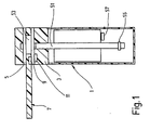
- a safety switch consists of a switching element 1 with a housing 3, which with the fixed part of a protective device is connectable.
- the housing 3 is penetrated by a head Actuator channel 5, which is open at both ends.
- a key-like actuator 7 insertable on the movable part of a Protective device can be attached, for example on a door or hood.
- the actuator 7 carries an actuator element 9 encapsulated in plastic, which is within the actuator channel 5 when the actuator 7 is complete is introduced into the actuator channel 5.
- the switching element 1 has on the edge of Actuator channel 5 a read head 11. With the actuator fully inserted 7, the actuator element 9 and the reading head 11 are opposite one another arranged and can interact with each other.
- the reading head 11 is connected to an evaluation device 13.
- the evaluation device 13 has connections 15 to which one Device supply voltage of 24 V is applied. With these connections 15 the inputs of a controller 17 are connected.
- the output of the regulator 17 outputs an internal supply voltage of 5 V.
- the Collector of an npn transistor 19, which is followed by a pnp transistor 21 is, as well as a first and, for security reasons, a second microprocessor 23 or 25 connected.
- the first microprocessor 23 is a Control line also monitored by controller 17. An exit from the first Microprocessor 23 is connected to the bases of transistors 19 via an amplifier and 21 connected.
- This coil 27 is inside the read head 11 on the Actuator channel 5 arranged side and runs with it Longitudinal axis parallel to this.
- the coil 27 is a capacitor 29 downstream, which is on the one hand via two resistors 31 to ground, and on the other hand via a receiving amplifier 33 with bandpass filter on one Input of the two microprocessors 23 and 25 is connected.
- Parallel to each of the two resistors 31 is one for safety reasons
- Level monitor 35 connected, one of which is connected to an input of the first microprocessor 23 and the other to an input of the second Microprocessor 25 is connected.
- the first microprocessor 23 generates a frequency of from the computer clock 125 kHz, with which he drives the two transistors 19 and 21, which alternately switch from the blocked to the saturated state.
- the oscillating circuit consisting of the coil 27 and the capacitor 29 becomes clock, whose resonance frequency is also 125 kHz, to vibrations excited.
- the coil 27 emits an alternating magnetic field.
- the resistors 31 limit the current in the resonant circuit and thus the amplitude of the alternating magnetic field.
- the Distance between actuator element 9 and reading head 11 set in which both can still work together. Because the resistors 31 double are present, the level monitors 35 can by comparing one Detect drift of one of the resistors 31.
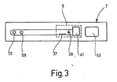
- An actuator coil 37 is provided in the actuator element 9 as an inductor, which on the side facing the reading head 11 in the longitudinal direction of the Actuator 7 is arranged.
- the actuator coil 37 forms together with one Actuator capacitor 39 a resonant circuit, to which an IC chip 41st lies in parallel. If, with the actuator fully inserted, 7 the actuator element 9 and the reading head 11 face each other, form the coil 27 and the actuator coil 37 a transformer, that is one Transformer. Since there is a gap between the two coils 27, 37, the transformer has a low degree of coupling (typically between 0.01 and 0.1).
- the magnetic radiated from the coil 27 Alternating field induces a voltage in the actuator coil 37 and thus excites an oscillation in the oscillating circuit 37, 39.
- the IC chip 41 has one Rectifier on, whereby he take energy from the resonant circuit 37, 39 can. Furthermore, the IC module 41 has an EEPROM, which is a 32 bit stores long code with which the actuator element 9 can be clearly identified is. The IC chip 41 modulates the amplitude in this code Oscillating circuit 37, 39 at a rate of 1 bit per msec. Actuator coil 37 couples back to the coil 27 in the read head 11, causing its resonant circuit 37, 39 is also modulated. This is via the receive amplifier 33 modulated signal supplied to the microprocessors 23 and 25.
- Each of the two microprocessors 23 and 25 has an EEPROM 43, in which a 32-bit code is stored, with which the reading head 11 is clearly identifiable. Place the two microprocessors 23 and 25 independently of one another whether the actuator 9 has a code at all is transmitted, and whether this to the code from the EEPROM 23rd fits, so whether the associated pair of actuator 9 and Read head 11 is opposite.
- the microprocessor only gives in the latter case 23 or 25 via an amplifier to a relay 45 the signal for closing a switch 47. For greater security, the closures of the Switch 47 positively driven NC contacts and lines provided, with which each microprocessor 23 and 25 the switching state of the respective other relay 45 can determine.
- the two switches 47 form the outputs of the safety switch and are connected in series, for example used, the voltage supply of the provided with the protective device Control machine. Is the distance between actuator element 9 and Read head 11 too large, for example if it is not in the actuator channel 5 inserted actuator 7 (i.e. an open protective device) the microprocessors 23, 25 do not find any suitable codes, so that they the signal to open the switch 47 and thus to switch off the Apply power to the machine.
- the switching element 1 has a in the longitudinal direction of the Housing 3 displaceable plunger 51, which preferably as an anchor Solenoid is designed.
- the plunger 51 can be perpendicular to it Cross the actuator channel 5 and move on the engage the opposite side in a recess of the housing 3.
- the actuator 7 has an opening 53 through which the plunger 51 engage can when the actuator 7 is fully inserted into the actuator channel 5.
- the plunger 51 is spring-loaded against the stroke direction of the magnet.
- the arrangement and the control of the solenoid is chosen so that when the actuator 7 is fully inserted into the actuator channel 5, the tappet 51 by reaching through the opening 53 into the recess in the head of the Housing 3 engages and locks the actuator 7.
- the plunger 51 is there only release the actuator 7 after switching off the machine when the machine has come to a standstill, so that it is prevented that the protective device can already be opened while it is running down the machine.
- this has a on further actuator element 55, which is formed like the actuator element 9 is.
- the switching element 1 has a further read head 57 in the housing 3 on, which is designed like the reading head 11.
- the further actuator element 55 and the further reading head 57 are arranged so that they are each other oppose when the plunger 51 locks the actuator 7.
- the one Another read head 57 further evaluation device has two Switch on, preferably with the switches 47 of the evaluation device 13 can be placed in series.
- the actuator 7 is made of plastic. At the opening 53 Fastening holes are provided at the opposite end, with which the actuator 7 is attached to the movable part of the protective device.
- One out Copper wire existing turn of the actuator coil 37 is from the Actuator element 9 out, on the actuator 7 along the Fastening holes 59 around and back to the actuator element 9. The turn can also be placed around the opening 53. In the event of a break of the actuator 7, this winding and thus the actuator coil 37 broken open so that the actuator element 9 is no longer on the magnetic Alternating field of the read head 11 can address.
- the Switching element 1 signals an open protective device, so that the Safety switch goes into the safe state, so switches off the power supply to the machine.
Description
- Fig. 1
- einen Schnitt durch das Ausführungsbeispiel,
- Fig. 2
- ein Blockschaltbild von Betätigerelement, Lesekopf und Auswerteeinrichtung,
- Fig. 3
- eine schematisierte Darstellung des Betätigers.
Claims (9)
- Sicherheitsschalter zur Überwachung von beweglichen Schutzeinrichtungen mitwobeia) einem Schaltglied (1), das wenigstens einen Lesekopf (11, 57) aufweist, undb) einem relativ zum Lesekopf (11, 57) bewegbaren Betätigerelement (9, 55), welches mit dem Lesekopf (11, 57) berührungslos zusammenwirkt,c) das Betätigerelement (9, 55) für das Zusammenwirken mit dem Lesekopf (11, 57) eine Induktivität (37) aufweist,d) das Betätigerelement (9, 55) in einem Speicher (41) eine elektronische Codierung enthält, welche das Betätigerelement (9, 55) eindeutig identifiziert,e) dem Lesekopf (11, 57) eine Auswerteeinrichtung (13) nachgeschaltet ist, welche in wenigstens einem weiteren Speicher (43) eine elektronische Codierung enthält, welche den Lesekopf (11, 57) oder das Schaltglied (1) eindeutig identifiziert,f) und diejenigen Teile (23, 25, 35, 43) der Auswerteeinrichtung (13), die für die Auswertung des vom Lesekopf (11, 57) aufgenommenen Signals vorgesehen sind, mindestens doppelt vorhanden sind.
- Sicherheitsschalter nach Anspruch 1, dadurch gekennzeichnet, daß der Lesekopf (11, 57) ebenfalls eine Induktivität (27) aufweist, welche über ein magnetisches Wechselfeld mit der Induktivität (37) des Betätigerelementes (9, 55) zusammenwirkt.
- Sicherheitsschalter nach Anspruch 2, dadurch gekennzeichnet, daß das Betätigerelement (9, 55) seine Energie zum Betrieb dem magnetischen Wechselfeld entnimmt.
- Sicherheitsschalter nach einem der Ansprüche 1 bis 3, dadurch gekennzeichnet, daß die Auswerteeinrichtung (13) wenigstens eine Vergleichseinrichtung (23, 25) aufweist zum Vergleich der vom Betätigerelement (9, 55) auf Anregung des Lesekopfes (11, 57) hin abgegebenen und vom Lesekopf (11, 57) aufgenommenen Codierung mit der in der Auswerteeinrichtung (13) gespeicherten Codierung.
- Sicherheitsschalter nach einem der Ansprüche 1 bis 4, dadurch gekennzeichnet, daß ein Betätiger (7) in ein Gehäuse (3) des Schaltgliedes (1) einführbar ist.
- Sicherheitsschalter nach Anspruch 5, dadurch gekennzeichnet, daß das Betätigerelement (9) am Betätiger (7) vorgesehen ist.
- Sicherheitsschalter nach Anspruch 5, dadurch gekennzeichnet, daß das Betätigerelement (55) auf einem den Betätiger (7) verriegelnden Stößel (51) vorgesehen ist.
- Sicherheitsschalter nach einem der Ansprüche 5 bis 7, dadurch gekennzeichnet, daß wenigstens eine Windung der Induktivität (37) des Betätigerelements (9) sich über nahezu die gesamte Länge des Betätigers (7) erstreckt.
- Verwendung eines Sicherheitsschalters nach einem der Ansprüche 1 bis 8 für eine Schutzeinrichtung einer Maschine oder einer Anlage.
Applications Claiming Priority (3)
| Application Number | Priority Date | Filing Date | Title |
|---|---|---|---|
| DE19711588 | 1997-03-20 | ||
| DE19711588A DE19711588A1 (de) | 1997-03-20 | 1997-03-20 | Sicherheitsschalter |
| PCT/EP1997/007302 WO1998043351A1 (de) | 1997-03-20 | 1997-12-24 | Sicherheitsschalter |
Publications (3)
| Publication Number | Publication Date |
|---|---|
| EP0968567A1 EP0968567A1 (de) | 2000-01-05 |
| EP0968567B1 true EP0968567B1 (de) | 2001-07-11 |
| EP0968567B2 EP0968567B2 (de) | 2008-01-09 |
Family
ID=7823991
Family Applications (1)
| Application Number | Title | Priority Date | Filing Date |
|---|---|---|---|
| EP97953925A Expired - Lifetime EP0968567B2 (de) | 1997-03-20 | 1997-12-24 | Sicherheitsschalter |
Country Status (6)
| Country | Link |
|---|---|
| US (1) | US6409083B1 (de) |
| EP (1) | EP0968567B2 (de) |
| JP (1) | JP2002501698A (de) |
| AT (1) | ATE203129T1 (de) |
| DE (2) | DE19711588A1 (de) |
| WO (1) | WO1998043351A1 (de) |
Cited By (7)
| Publication number | Priority date | Publication date | Assignee | Title |
|---|---|---|---|---|
| DE10228232C1 (de) * | 2002-06-25 | 2003-09-25 | Schmersal K A Gmbh & Co | Betätiger für einen Sicherheitsschalter |
| DE10334653A1 (de) * | 2003-07-21 | 2005-03-03 | Pilz Gmbh & Co. Kg | Verfahren und Vorrichtung zum sicheren Überwachen einer Schließposition zweier relativ zueinander beweglicher Teile |
| DE10348884A1 (de) * | 2003-10-14 | 2005-05-25 | Pilz Gmbh & Co. Kg | Sicherheitsschalter, insbesondere Not-Aus-Schalter, zum sicheren Abschalten eines gefahrbringenden Gerätes |
| DE102004002438A1 (de) * | 2004-01-09 | 2005-09-22 | Pilz Gmbh & Co. Kg | Sicherheitsschalter zum Überwachen einer Schließposition zweier relativ zueinander beweglicher Teile |
| EP1928091A1 (de) | 2006-12-01 | 2008-06-04 | Siemens Aktiengesellschaft | Sensoreinheit mit Sicherheitssystem |
| US7746233B2 (en) | 2004-01-09 | 2010-06-29 | Pilz Gmbh & Co. Kg | Safety switch for monitoring a closed position of two parts moveable relative to one another |
| EP2637067A2 (de) | 2012-03-07 | 2013-09-11 | Pilz GmbH & Co. KG | Sensoranordnung zum Detektieren eines sicheren Anlagenzustandes einer automatisiert betriebenen Anlage |
Families Citing this family (43)
| Publication number | Priority date | Publication date | Assignee | Title |
|---|---|---|---|---|
| DE19917211C1 (de) | 1999-04-16 | 2000-11-16 | Euchner Gmbh & Co | Vorrichtung zum Schalten einer Verbindung in Abhängigkeit des Zustandes einer zu überwachenden Einrichtung, insbesondere Sicherheitsschalter |
| DE19917212A1 (de) | 1999-04-16 | 2000-11-02 | Euchner Gmbh & Co | Vorrichtung zum Schalten einer Verbindung in Abhängigkeit des Zustandes einer zu überwachenden Einrichtung, insbesondere Sicherheitsschalter |
| DE19934370C2 (de) * | 1999-07-22 | 2001-05-17 | Schmersal K A Gmbh & Co | Überwachungseinrichtung |
| US6539760B1 (en) | 1999-05-24 | 2003-04-01 | K.A. Schmersal Gmbh & Co. | Monitoring device |
| GB2353361A (en) * | 1999-08-18 | 2001-02-21 | Walton Green Andrew John Scott | Proximity switch comprising relatively movable tuned circuits |
| DE19953898C5 (de) * | 1999-11-10 | 2004-07-01 | K.A. Schmersal Gmbh & Co | Zugangsschutzeinrichtung |
| DE10043237C1 (de) * | 2000-09-02 | 2001-11-29 | Schmersal K A Gmbh & Co | Codegeber-Detektionseinrichtung |
| DE10216225A1 (de) * | 2002-04-08 | 2003-10-30 | Euchner Gmbh & Co | Elektromagnetisches Zuhaltesystem eines Sicherheitsschalters |
| DE10222186C1 (de) * | 2002-05-18 | 2003-10-09 | Schmersal K A Gmbh & Co | Sicherheitsschalter |
| DE10230564A1 (de) * | 2002-07-05 | 2004-01-29 | Gerhard Thiel | Kodierte Verriegelungseinrichtung mit Zuhaltung |
| DE10234984B4 (de) * | 2002-07-31 | 2006-07-06 | Siemens Ag | Schalteinrichtung |
| DE10305704B3 (de) * | 2003-02-12 | 2004-06-24 | K.A. Schmersal Gmbh & Co | Sicherheitszuhaltung |
| EP1455454A3 (de) * | 2003-03-07 | 2009-09-30 | Pilz Auslandsbeteiligungen GmbH | Induktive Überwachungsvorrichtung und Verfahren zur Überwachung des Abstands zwischen einer ersten und einer zweiten Spule |
| DE10348527B3 (de) * | 2003-10-18 | 2005-08-18 | K.A. Schmersal Gmbh & Co | Magnetischer Sicherheitsverschluß für eine bewegliche Schutzeinrichtung |
| NL1025100C1 (nl) * | 2003-12-22 | 2005-06-23 | Johannes Leonardus Henr Ceelen | Elektronische beveiligingsinrichting. |
| DE102004016632B4 (de) * | 2004-03-29 | 2006-03-23 | Pilz Gmbh & Co. Kg | Sicherheitsschalter zum Überwachen einer Schließposition zweier relativ zueinander beweglicher Teile |
| DE502005008743D1 (de) * | 2004-03-29 | 2010-02-04 | Pilz Gmbh & Co Kg | Sicherheitsschalter zum überwachen einer schliessposition zweier relativ zueinander beweglicher teile |
| EP1738383B2 (de) | 2004-04-19 | 2023-01-11 | Pilz GmbH & Co. KG | Meldegerät für eine sicherheitsschaltung |
| DE102004049024B3 (de) * | 2004-09-20 | 2006-04-13 | K.A. Schmersal Holding Kg | Positionsüberwachungseinrichtung |
| EP1677167B1 (de) * | 2005-01-03 | 2013-05-22 | K. A. Schmersal GmbH & Co. KG | Betriebsartenwahlschalter |
| DE102005013102A1 (de) * | 2005-03-18 | 2006-09-21 | K.A. Schmersal Holding Kg | Berührungslos wirkender Schalter |
| GB0601990D0 (en) * | 2006-02-01 | 2006-03-15 | Eja Ltd | Safety switch |
| DE102006032226B4 (de) | 2006-07-07 | 2009-12-10 | Pilz Gmbh & Co. Kg | Verfahren und Vorrichtung zur sicheren Abstandsüberwachung |
| ATE506748T1 (de) * | 2006-09-13 | 2011-05-15 | Siemens Ag | Verfahren und vorrichtung zur beschleunigten erkennung eines auslösefalls eines berührungslosen schaltsystems |
| DE102006046437B4 (de) * | 2006-09-25 | 2009-04-09 | Euchner Gmbh + Co. Kg | Vorrichtung zum Überwachen des Zustandes einer sicherheitsrelevanten Einrichtung |
| DE202006015768U1 (de) | 2006-10-14 | 2006-12-14 | Sick Ag | Vorrichtung zum Überwachen der Annäherung zweier relativ zueinander beweglicher Teile |
| DK2181234T3 (da) | 2007-08-07 | 2017-11-20 | Telesteps Ab | Sæt af stigetilbehørsdele |
| GB0801706D0 (en) | 2008-01-31 | 2008-03-05 | Eja Ltd | Safety switch |
| US8779778B2 (en) | 2009-04-28 | 2014-07-15 | Omron Corporation | Proximity switch |
| DE102009059050B4 (de) | 2009-12-15 | 2017-10-12 | Euchner Gmbh + Co. Kg | Zuhaltesystem für einen Sicherheitsschalter und Sicherheitsschalter mit einem solchen Zuhaltesystem |
| DE102010034472B4 (de) | 2010-08-05 | 2017-10-12 | Euchner Gmbh + Co. Kg | Zuhalteeinrichtung für eine Vorrichtung zum Überwachen des Zustandes einer Schutzeinrichtung einer Maschine |
| DE102010035765B4 (de) | 2010-08-20 | 2012-03-22 | Euchner Gmbh + Co. Kg | Vorrichtung zum Überwachen des Zustandes einer Schutzeinrichtung einer Maschine, insbesondere Sicherheitsschalter, und Verfahren zum Betrieb einer solchen Vorrichtung |
| DE102011119413A1 (de) | 2011-11-21 | 2013-05-23 | Euchner Gmbh + Co. Kg | Vorrichtung zum Steuern des Betriebs einer Maschine, Sperreinsatz für eine solche Vorrichtung und zugehöriges Betriebsverfahren |
| ITVI20110342A1 (it) | 2011-12-29 | 2013-06-30 | Pizzato Elettrica Srl | Dispositivo di sicurezza elettronico per una barriera di protezione |
| DE102012109311B4 (de) | 2012-10-01 | 2022-01-05 | Pilz Gmbh & Co. Kg | Vorrichtung zum sicheren Überwachen einer Schließposition zweier relativ zueinander beweglicher Teile |
| DE102012021968B4 (de) | 2012-10-31 | 2015-10-22 | Euchner Gmbh + Co. Kg | Vorrichtung zum lösbaren Arretieren eines vorgebbaren Zustandes einer Einrichtung sowie Sicherheitsschalter mit einer solchen Vorrichtung |
| DE102013014456B4 (de) * | 2013-08-30 | 2016-03-24 | Euchner Gmbh + Co. Kg | Betätiger eines Sicherheitsschalters sowie Sicherheitsschalter mit einem solchen Betätiger |
| DE102015113937A1 (de) | 2015-08-21 | 2017-02-23 | Elobau Gmbh & Co. Kg | Drahtloses Überwachungssystem |
| IT201600117298A1 (it) * | 2016-11-21 | 2018-05-21 | Pizzato Elettrica Srl | Interruttore di sicurezza con cpu differenziate |
| CH714313A1 (de) * | 2017-11-09 | 2019-05-15 | Elesta Gmbh Ostfildern De Zweigniederlassung Bad Ragaz | Vorrichtung mit einem Sensor und einem Betätiger, insbesondere zur Verwendung als Türkontaktschalter, und Verfahren zum Testen der Vorrichtung. |
| JP7010755B2 (ja) | 2018-04-13 | 2022-01-26 | 株式会社キーエンス | 安全ドアスイッチ |
| JP7122851B2 (ja) | 2018-04-13 | 2022-08-22 | 株式会社キーエンス | 安全スイッチ |
| JP2021173062A (ja) * | 2020-04-24 | 2021-11-01 | パナソニックIpマネジメント株式会社 | 安全スイッチ及び記憶制御方法 |
Family Cites Families (17)
| Publication number | Priority date | Publication date | Assignee | Title |
|---|---|---|---|---|
| JPS61196080A (ja) * | 1985-02-21 | 1986-08-30 | 日産自動車株式会社 | 無線式利用者識別装置 |
| DE3600979A1 (de) * | 1986-01-15 | 1987-07-16 | Rheinmetall Gmbh | Beruehrungsloser signalgeber |
| DE3616389A1 (de) * | 1986-05-15 | 1987-11-19 | Turck Werner Kg | Beruehrungslos wirkender naeherungsschalter |
| JP2546842B2 (ja) * | 1987-06-16 | 1996-10-23 | 日産自動車株式会社 | 車両用施解錠制御装置 |
| DE3837218A1 (de) | 1988-11-02 | 1990-05-03 | Elektronik Geraetewerk Gmbh | Kriech- und drehbewegungsueberwachung bei schutzeinrichtung mit normaler oder erhoehter sicherheit typ ebud-00 (...99) |
| CH680082A5 (de) * | 1989-12-15 | 1992-06-15 | Bauer Kaba Ag | |
| JPH03228988A (ja) * | 1990-02-02 | 1991-10-09 | Daishowa Seiki Co Ltd | 扉開閉のための識別装置 |
| GB9017910D0 (en) * | 1990-08-15 | 1990-09-26 | Vaseal Electronics Limited | Improvements in and relating to proximity switches |
| DE4041550C3 (de) | 1990-12-22 | 2003-08-28 | Schmersal K A Gmbh & Co | Sicherheitseinrichtung mit mindestens einem berührungslosen Geber |
| DE4303367C1 (de) † | 1993-02-05 | 1994-02-24 | Schmersal K A Gmbh & Co | Sicherheitsschalter |
| DE4412653C2 (de) † | 1994-04-13 | 1997-01-09 | Schmersal K A Gmbh & Co | Überwachungseinrichtung |
| DE19501004C2 (de) * | 1994-05-03 | 1999-09-16 | Telefunken Microelectron | Verfahren zur verifizierbaren Datenübertragung zwischen einem Transponder und einem Lesegerät |
| DE4438039A1 (de) | 1994-10-25 | 1996-05-02 | Leon Helma Christina | Elektronisches Schaltgerät für die Erfassung des Betätigungszustandes von taktilen Sensoren |
| JP3670719B2 (ja) * | 1995-07-24 | 2005-07-13 | 株式会社ユーシン | キーレスエントリーシステム |
| US6243004B1 (en) * | 1996-08-22 | 2001-06-05 | Kenneth E. Flick | Vehicle security system with inductive coupling to a vehicle having a data communications bus and related methods |
| JPH10159419A (ja) * | 1996-11-29 | 1998-06-16 | Aisin Seiki Co Ltd | オートドアロック制御装置 |
| JP3256666B2 (ja) * | 1996-12-25 | 2002-02-12 | 三菱電機株式会社 | 車両用リモコン装置および車両セキュリティ装置 |
-
1997
- 1997-03-20 DE DE19711588A patent/DE19711588A1/de not_active Withdrawn
- 1997-12-24 DE DE59704043T patent/DE59704043D1/de not_active Expired - Lifetime
- 1997-12-24 EP EP97953925A patent/EP0968567B2/de not_active Expired - Lifetime
- 1997-12-24 US US09/319,042 patent/US6409083B1/en not_active Expired - Lifetime
- 1997-12-24 AT AT97953925T patent/ATE203129T1/de not_active IP Right Cessation
- 1997-12-24 WO PCT/EP1997/007302 patent/WO1998043351A1/de active IP Right Grant
- 1997-12-24 JP JP54477698A patent/JP2002501698A/ja active Pending
Cited By (11)
| Publication number | Priority date | Publication date | Assignee | Title |
|---|---|---|---|---|
| DE10228232C1 (de) * | 2002-06-25 | 2003-09-25 | Schmersal K A Gmbh & Co | Betätiger für einen Sicherheitsschalter |
| DE10334653A1 (de) * | 2003-07-21 | 2005-03-03 | Pilz Gmbh & Co. Kg | Verfahren und Vorrichtung zum sicheren Überwachen einer Schließposition zweier relativ zueinander beweglicher Teile |
| DE10334653B4 (de) * | 2003-07-21 | 2005-06-09 | Pilz Gmbh & Co. Kg | Verfahren und Vorrichtung zum sicheren Überwachen einer Schließposition zweier relativ zueinander beweglicher Teile |
| US7548159B2 (en) | 2003-07-21 | 2009-06-16 | Pilz Gmbh & Co. Kg | Method and device for reliably monitoring a closed position of two parts moveable relative to one another |
| DE10348884A1 (de) * | 2003-10-14 | 2005-05-25 | Pilz Gmbh & Co. Kg | Sicherheitsschalter, insbesondere Not-Aus-Schalter, zum sicheren Abschalten eines gefahrbringenden Gerätes |
| DE102004002438A1 (de) * | 2004-01-09 | 2005-09-22 | Pilz Gmbh & Co. Kg | Sicherheitsschalter zum Überwachen einer Schließposition zweier relativ zueinander beweglicher Teile |
| US7746233B2 (en) | 2004-01-09 | 2010-06-29 | Pilz Gmbh & Co. Kg | Safety switch for monitoring a closed position of two parts moveable relative to one another |
| EP1928091A1 (de) | 2006-12-01 | 2008-06-04 | Siemens Aktiengesellschaft | Sensoreinheit mit Sicherheitssystem |
| US7667354B2 (en) | 2006-12-01 | 2010-02-23 | Siemens Aktiengesellschaft | Sensor unit with safety system |
| EP2637067A2 (de) | 2012-03-07 | 2013-09-11 | Pilz GmbH & Co. KG | Sensoranordnung zum Detektieren eines sicheren Anlagenzustandes einer automatisiert betriebenen Anlage |
| US9423784B2 (en) | 2012-03-07 | 2016-08-23 | Pilz Gmbh & Co. Kg | Sensor arrangement for detecting a safe installation state of an installation operated in an automated manner |
Also Published As
| Publication number | Publication date |
|---|---|
| EP0968567B2 (de) | 2008-01-09 |
| US6409083B1 (en) | 2002-06-25 |
| DE19711588A1 (de) | 1998-09-24 |
| WO1998043351A1 (de) | 1998-10-01 |
| EP0968567A1 (de) | 2000-01-05 |
| DE59704043D1 (de) | 2001-08-16 |
| JP2002501698A (ja) | 2002-01-15 |
| ATE203129T1 (de) | 2001-07-15 |
Similar Documents
| Publication | Publication Date | Title |
|---|---|---|
| EP0968567B1 (de) | Sicherheitsschalter | |
| EP0986176B1 (de) | Berührungsloser Sicherheitsschalter | |
| EP2041871B1 (de) | Verfahren und vorrichtung zur sicheren abstandsüberwachung | |
| DE3501482A1 (de) | Einrichtung zur kontaktlosen kopplung der steuerungs- und leistungsstroeme zwischen der elektronik am schliesszylinder und der elektronik im schluessel bei einer elektronisch/mechanischen schliesseinrichtung | |
| EP1479030B1 (de) | Mit einem transponder betätigbare schaltvorrichtung | |
| WO1992018410A1 (de) | Überwachungseinrichtung für eine steuervorrichtung | |
| EP0368018A2 (de) | Beschlag, insbesondere für Türen oder dergleichen | |
| EP0187363B1 (de) | Mechanisch und nichtmechanisch codierter Schlüssel sowie dadurch zu betätigendes Schloss | |
| DE19953898C5 (de) | Zugangsschutzeinrichtung | |
| DE10334653A1 (de) | Verfahren und Vorrichtung zum sicheren Überwachen einer Schließposition zweier relativ zueinander beweglicher Teile | |
| DE102005009489A1 (de) | Elektronikbaugruppe für eine Positionserfassungseinrichtung mit einer Weckvorrichtung zum Verarbeiten eines Aufweck-Strompulses einer Wiegand-Spule | |
| CH658735A5 (de) | Vorrichtung zur identifizierung einer information. | |
| DE102006046437B4 (de) | Vorrichtung zum Überwachen des Zustandes einer sicherheitsrelevanten Einrichtung | |
| DE4240628A1 (de) | Überwachungseinrichtung an einer Textilmaschine | |
| EP0377128A1 (de) | Zündanlage für Kraftfahrzeuge | |
| EP3517822A1 (de) | Zuhaltung mit freigabesignal | |
| EP3502539A1 (de) | Schutzeinrichtung sowie verfahren zum betreiben einer schutzeinrichtung | |
| EP1702409A1 (de) | Sicherheitsschalter zum überwachen einer schliessposition zweier relativ zueinander beweglicher teile | |
| DE10252025A1 (de) | Schloß | |
| EP2080151B1 (de) | Vorrichtung und verfahren zum betrieb eines schreib-/lesegeräts | |
| DE102004016632B4 (de) | Sicherheitsschalter zum Überwachen einer Schließposition zweier relativ zueinander beweglicher Teile | |
| EP1473511A2 (de) | Zugangsschutzeinrichtung | |
| WO2009000870A1 (de) | Elektronische zustandserfassungseinrichtung | |
| EP1730759B1 (de) | Sicherheitsschalter zum überwachen einer schliessposition zweier relativ zueinander beweglicher teile | |
| DE4341333B4 (de) | Verfahren zum Betreiben einer elektronischen Wegfahrsperre und elektronische Wegfahrsperre für Kraftfahrzeuge |
Legal Events
| Date | Code | Title | Description |
|---|---|---|---|
| PUAI | Public reference made under article 153(3) epc to a published international application that has entered the european phase |
Free format text: ORIGINAL CODE: 0009012 |
|
| 17P | Request for examination filed |
Effective date: 19990121 |
|
| AK | Designated contracting states |
Kind code of ref document: A1 Designated state(s): AT BE CH DE FR GB IT LI NL SE |
|
| GRAG | Despatch of communication of intention to grant |
Free format text: ORIGINAL CODE: EPIDOS AGRA |
|
| GRAG | Despatch of communication of intention to grant |
Free format text: ORIGINAL CODE: EPIDOS AGRA |
|
| GRAH | Despatch of communication of intention to grant a patent |
Free format text: ORIGINAL CODE: EPIDOS IGRA |
|
| 17Q | First examination report despatched |
Effective date: 20001129 |
|
| GRAH | Despatch of communication of intention to grant a patent |
Free format text: ORIGINAL CODE: EPIDOS IGRA |
|
| GRAA | (expected) grant |
Free format text: ORIGINAL CODE: 0009210 |
|
| AK | Designated contracting states |
Kind code of ref document: B1 Designated state(s): AT BE CH DE FR GB IT LI NL SE |
|
| REF | Corresponds to: |
Ref document number: 203129 Country of ref document: AT Date of ref document: 20010715 Kind code of ref document: T |
|
| REG | Reference to a national code |
Ref country code: CH Ref legal event code: NV Representative=s name: ISLER & PEDRAZZINI AG Ref country code: CH Ref legal event code: EP |
|
| REF | Corresponds to: |
Ref document number: 59704043 Country of ref document: DE Date of ref document: 20010816 |
|
| ITF | It: translation for a ep patent filed |
Owner name: BUZZI, NOTARO&ANTONIELLI D'OULX |
|
| ET | Fr: translation filed | ||
| GBT | Gb: translation of ep patent filed (gb section 77(6)(a)/1977) |
Effective date: 20011011 |
|
| REG | Reference to a national code |
Ref country code: GB Ref legal event code: IF02 |
|
| PLBQ | Unpublished change to opponent data |
Free format text: ORIGINAL CODE: EPIDOS OPPO |
|
| PLBI | Opposition filed |
Free format text: ORIGINAL CODE: 0009260 |
|
| PLBF | Reply of patent proprietor to notice(s) of opposition |
Free format text: ORIGINAL CODE: EPIDOS OBSO |
|
| 26 | Opposition filed |
Opponent name: K.A. SCHMERSAL GMBH & CO. Effective date: 20020409 |
|
| NLR1 | Nl: opposition has been filed with the epo |
Opponent name: K.A. SCHMERSAL GMBH & CO. |
|
| PLBF | Reply of patent proprietor to notice(s) of opposition |
Free format text: ORIGINAL CODE: EPIDOS OBSO |
|
| PLBF | Reply of patent proprietor to notice(s) of opposition |
Free format text: ORIGINAL CODE: EPIDOS OBSO |
|
| TPAD | Observations filed by third parties |
Free format text: ORIGINAL CODE: EPIDOS TIPA |
|
| APBP | Date of receipt of notice of appeal recorded |
Free format text: ORIGINAL CODE: EPIDOSNNOA2O |
|
| APAH | Appeal reference modified |
Free format text: ORIGINAL CODE: EPIDOSCREFNO |
|
| APAH | Appeal reference modified |
Free format text: ORIGINAL CODE: EPIDOSCREFNO |
|
| APAL | Date of receipt of statement of grounds of an appeal modified |
Free format text: ORIGINAL CODE: EPIDOSCNOA3O |
|
| APBQ | Date of receipt of statement of grounds of appeal recorded |
Free format text: ORIGINAL CODE: EPIDOSNNOA3O |
|
| APBU | Appeal procedure closed |
Free format text: ORIGINAL CODE: EPIDOSNNOA9O |
|
| REG | Reference to a national code |
Ref country code: CH Ref legal event code: PCAR Free format text: ISLER & PEDRAZZINI AG;POSTFACH 1772;8027 ZUERICH (CH) |
|
| PUAH | Patent maintained in amended form |
Free format text: ORIGINAL CODE: 0009272 |
|
| STAA | Information on the status of an ep patent application or granted ep patent |
Free format text: STATUS: PATENT MAINTAINED AS AMENDED |
|
| 27A | Patent maintained in amended form |
Effective date: 20080109 |
|
| AK | Designated contracting states |
Kind code of ref document: B2 Designated state(s): AT BE CH DE FR GB IT LI NL SE |
|
| REG | Reference to a national code |
Ref country code: CH Ref legal event code: AEN Free format text: AUFRECHTERHALTUNG DES PATENTES IN GEAENDERTER FORM |
|
| NLR2 | Nl: decision of opposition |
Effective date: 20080109 |
|
| REG | Reference to a national code |
Ref country code: SE Ref legal event code: RPEO |
|
| GBTA | Gb: translation of amended ep patent filed (gb section 77(6)(b)/1977) |
Effective date: 20080416 |
|
| NLR3 | Nl: receipt of modified translations in the netherlands language after an opposition procedure | ||
| ET3 | Fr: translation filed ** decision concerning opposition | ||
| PLAB | Opposition data, opponent's data or that of the opponent's representative modified |
Free format text: ORIGINAL CODE: 0009299OPPO |
|
| PGFP | Annual fee paid to national office [announced via postgrant information from national office to epo] |
Ref country code: NL Payment date: 20081231 Year of fee payment: 12 Ref country code: CH Payment date: 20081229 Year of fee payment: 12 |
|
| PGFP | Annual fee paid to national office [announced via postgrant information from national office to epo] |
Ref country code: AT Payment date: 20081106 Year of fee payment: 12 |
|
| PGFP | Annual fee paid to national office [announced via postgrant information from national office to epo] |
Ref country code: BE Payment date: 20081128 Year of fee payment: 12 |
|
| BERE | Be: lapsed |
Owner name: *EUCHNER G.M.B.H. + CO. Effective date: 20091231 |
|
| REG | Reference to a national code |
Ref country code: NL Ref legal event code: V1 Effective date: 20100701 |
|
| REG | Reference to a national code |
Ref country code: CH Ref legal event code: PL |
|
| PG25 | Lapsed in a contracting state [announced via postgrant information from national office to epo] |
Ref country code: AT Free format text: LAPSE BECAUSE OF NON-PAYMENT OF DUE FEES Effective date: 20091224 |
|
| PG25 | Lapsed in a contracting state [announced via postgrant information from national office to epo] |
Ref country code: NL Free format text: LAPSE BECAUSE OF NON-PAYMENT OF DUE FEES Effective date: 20100701 Ref country code: LI Free format text: LAPSE BECAUSE OF NON-PAYMENT OF DUE FEES Effective date: 20091231 Ref country code: CH Free format text: LAPSE BECAUSE OF NON-PAYMENT OF DUE FEES Effective date: 20091231 Ref country code: BE Free format text: LAPSE BECAUSE OF NON-PAYMENT OF DUE FEES Effective date: 20091231 |
|
| REG | Reference to a national code |
Ref country code: DE Ref legal event code: R082 Ref document number: 59704043 Country of ref document: DE Representative=s name: RUCKH, RAINER, DIPL.-PHYS. DR.RER.NAT., DE |
|
| REG | Reference to a national code |
Ref country code: FR Ref legal event code: PLFP Year of fee payment: 19 |
|
| PGFP | Annual fee paid to national office [announced via postgrant information from national office to epo] |
Ref country code: GB Payment date: 20151221 Year of fee payment: 19 |
|
| PGFP | Annual fee paid to national office [announced via postgrant information from national office to epo] |
Ref country code: SE Payment date: 20151221 Year of fee payment: 19 Ref country code: FR Payment date: 20151221 Year of fee payment: 19 |
|
| PGFP | Annual fee paid to national office [announced via postgrant information from national office to epo] |
Ref country code: IT Payment date: 20151228 Year of fee payment: 19 Ref country code: DE Payment date: 20160109 Year of fee payment: 19 |
|
| REG | Reference to a national code |
Ref country code: DE Ref legal event code: R119 Ref document number: 59704043 Country of ref document: DE |
|
| REG | Reference to a national code |
Ref country code: SE Ref legal event code: EUG |
|
| GBPC | Gb: european patent ceased through non-payment of renewal fee |
Effective date: 20161224 |
|
| PG25 | Lapsed in a contracting state [announced via postgrant information from national office to epo] |
Ref country code: SE Free format text: LAPSE BECAUSE OF NON-PAYMENT OF DUE FEES Effective date: 20161225 |
|
| REG | Reference to a national code |
Ref country code: FR Ref legal event code: ST Effective date: 20170831 |
|
| PG25 | Lapsed in a contracting state [announced via postgrant information from national office to epo] |
Ref country code: IT Free format text: LAPSE BECAUSE OF NON-PAYMENT OF DUE FEES Effective date: 20161224 Ref country code: FR Free format text: LAPSE BECAUSE OF NON-PAYMENT OF DUE FEES Effective date: 20170102 |
|
| PG25 | Lapsed in a contracting state [announced via postgrant information from national office to epo] |
Ref country code: DE Free format text: LAPSE BECAUSE OF NON-PAYMENT OF DUE FEES Effective date: 20170701 Ref country code: GB Free format text: LAPSE BECAUSE OF NON-PAYMENT OF DUE FEES Effective date: 20161224 |