EP0968397B1 - Tour de refroidissement hybride - Google Patents
Tour de refroidissement hybride Download PDFInfo
- Publication number
- EP0968397B1 EP0968397B1 EP98966492A EP98966492A EP0968397B1 EP 0968397 B1 EP0968397 B1 EP 0968397B1 EP 98966492 A EP98966492 A EP 98966492A EP 98966492 A EP98966492 A EP 98966492A EP 0968397 B1 EP0968397 B1 EP 0968397B1
- Authority
- EP
- European Patent Office
- Prior art keywords
- cooling
- tower
- air
- section
- water distribution
- Prior art date
- Legal status (The legal status is an assumption and is not a legal conclusion. Google has not performed a legal analysis and makes no representation as to the accuracy of the status listed.)
- Expired - Lifetime
Links
- 238000001816 cooling Methods 0.000 title claims description 77
- XLYOFNOQVPJJNP-UHFFFAOYSA-N water Substances O XLYOFNOQVPJJNP-UHFFFAOYSA-N 0.000 claims description 40
- 238000009826 distribution Methods 0.000 claims description 23
- 238000002156 mixing Methods 0.000 claims description 4
- 230000002093 peripheral effect Effects 0.000 claims 1
- 239000003570 air Substances 0.000 description 40
- 239000000498 cooling water Substances 0.000 description 9
- 238000000034 method Methods 0.000 description 5
- 239000012080 ambient air Substances 0.000 description 3
- 239000000203 mixture Substances 0.000 description 3
- 229920006395 saturated elastomer Polymers 0.000 description 3
- 230000001174 ascending effect Effects 0.000 description 1
- 238000010586 diagram Methods 0.000 description 1
- 238000010438 heat treatment Methods 0.000 description 1
- 238000009434 installation Methods 0.000 description 1
- 238000004519 manufacturing process Methods 0.000 description 1
- 238000002844 melting Methods 0.000 description 1
- 230000008018 melting Effects 0.000 description 1
- 230000001105 regulatory effect Effects 0.000 description 1
Images

Classifications
-
- F—MECHANICAL ENGINEERING; LIGHTING; HEATING; WEAPONS; BLASTING
- F28—HEAT EXCHANGE IN GENERAL
- F28F—DETAILS OF HEAT-EXCHANGE AND HEAT-TRANSFER APPARATUS, OF GENERAL APPLICATION
- F28F27/00—Control arrangements or safety devices specially adapted for heat-exchange or heat-transfer apparatus
- F28F27/003—Control arrangements or safety devices specially adapted for heat-exchange or heat-transfer apparatus specially adapted for cooling towers
-
- F—MECHANICAL ENGINEERING; LIGHTING; HEATING; WEAPONS; BLASTING
- F28—HEAT EXCHANGE IN GENERAL
- F28C—HEAT-EXCHANGE APPARATUS, NOT PROVIDED FOR IN ANOTHER SUBCLASS, IN WHICH THE HEAT-EXCHANGE MEDIA COME INTO DIRECT CONTACT WITHOUT CHEMICAL INTERACTION
- F28C1/00—Direct-contact trickle coolers, e.g. cooling towers
- F28C1/14—Direct-contact trickle coolers, e.g. cooling towers comprising also a non-direct contact heat exchange
-
- F—MECHANICAL ENGINEERING; LIGHTING; HEATING; WEAPONS; BLASTING
- F28—HEAT EXCHANGE IN GENERAL
- F28F—DETAILS OF HEAT-EXCHANGE AND HEAT-TRANSFER APPARATUS, OF GENERAL APPLICATION
- F28F25/00—Component parts of trickle coolers
- F28F25/02—Component parts of trickle coolers for distributing, circulating, and accumulating liquid
-
- Y—GENERAL TAGGING OF NEW TECHNOLOGICAL DEVELOPMENTS; GENERAL TAGGING OF CROSS-SECTIONAL TECHNOLOGIES SPANNING OVER SEVERAL SECTIONS OF THE IPC; TECHNICAL SUBJECTS COVERED BY FORMER USPC CROSS-REFERENCE ART COLLECTIONS [XRACs] AND DIGESTS
- Y02—TECHNOLOGIES OR APPLICATIONS FOR MITIGATION OR ADAPTATION AGAINST CLIMATE CHANGE
- Y02B—CLIMATE CHANGE MITIGATION TECHNOLOGIES RELATED TO BUILDINGS, e.g. HOUSING, HOUSE APPLIANCES OR RELATED END-USER APPLICATIONS
- Y02B30/00—Energy efficient heating, ventilation or air conditioning [HVAC]
- Y02B30/70—Efficient control or regulation technologies, e.g. for control of refrigerant flow, motor or heating
Definitions
- the invention relates to a hybrid cooling tower.
- a hybrid cooling tower (wet-dry cooling tower) according to the DE 196 11 627 A1 describes a subset of that originating from a cooling process hot water to be cooled in one wet cooling section and the other Partial quantity in a dry cooling section cooled by air. The hot water but can also completely through the dry cooling section and then be led through the wet cooling section.
- the hot water led over the wet cooling part is over the main part of the tower cross-section water distribution sprayed on the trickle internals underneath. From the trickle internals the chilled water drips into a collecting basin, from where it returns to the Cooling process is supplied.
- the cooling the hot water in the wet cooling section Air flows through those located below the trickle internals in the tower wall Air inlet openings in and countercurrent upwards. To promote the Airflow is into the tower outlet opening located at the top of the hybrid cooling tower a suction fan integrated.
- This fan also draws the cooling air above the water distribution Dry cooling elements arranged on the circumference of the cooling tower of the dry cooling section. In the area between the water distribution, the Dry cooling elements and the fan are provided with air mix fittings.
- roller shutters or blinds at the air inlet openings for the wet cooling section however, special measures are required to ensure that Ensure function even in winter. This includes, for example, trace heating etc. known.
- US Pat. No. 3,994,999 also sees a hybrid cooling tower at the air inlet openings blinds for the wet cooling section.
- the air intake openings extend over the entire height of the wet cooling section. Air mixing internals are not provided.
- a hybrid cooling tower is known from DE 27 43 601 A1, which is in the area between the water distribution, the dry cooling elements and the fan has no air mix internals.
- this hybrid cooling tower in addition to that extending above the trickle internals Water distribution
- DE 29 01 156 A1 shows a pure wet cooling tower, in which the Frost protection in winter the one above the trickle internals Water distribution is divided into areas that are switched on and off can. In this way, the one entering the trickle internals flows from below Air once through areas that are exposed to water and once through areas that are not subjected to exposure. Through the Reduction of the heat exchange area while increasing the Rainproof you can achieve frost-proof operation. The state plays here the air escaping from the different areas no role in the regulation.
- the object of the invention is based on the prior art to create a hybrid cooling tower, which is a steam-free operation guaranteed with noticeably reduced production and operating expenses.
- a major advantage of the invention is that the previously necessary Control units such as roller shutters, blinds, additional fans and the associated control and drive devices, now complete can be omitted.
- the effort for creating and operating a This significantly reduces the hybrid cooling tower.
- the Tower discharge opening integrated, suction or pushing fan always works with approximately the same amount of air and pressure, so that it does not have to be designed for a special application. It a standardized fan can be used.
- the invention can be used for hybrid cooling towers which are round in horizontal cross section as well as those with angular configuration. Switching off a section or several sections can e.g. with the help of shut-off devices such as valves.
- the dry cooling part can have vertically and / or horizontally arranged finned tubes exhibit.
- a section of the tower axis lying adjacent Water distribution can be switched off from the water supply.
- Core circuitry can advantageously occur in the center of the cooling tower strong oversaturation of those emerging from the wet cooling section with moisture saturated air. This will make the need for drier Air reduced.
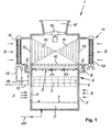
- FIG. 1 denotes a hybrid cooling tower.
- the hybrid cooling tower 1 is used in a cooling process, e.g. heated in a turbine steam condenser Cooling water recooled.
- the hybrid cooling tower 1 has an angular configuration in horizontal cross section on.
- a collecting basin 2 for the recooled Cooling water trained.
- the tower wall 4 is above the water level 3 perforated so that air inlet openings 5 are formed.
- Above the A wet cooling part 6 is arranged in the air inlet openings 5.
- This has trickle internals 7, which extend over the entire tower cross section.
- the trickle internals 7 are heated from a channel 8 Charged cooling water that surrounds the hybrid cooling tower 1 on the outside. The heated ...
- Above channel 8 for loading the wet cooling section is a dry cooling part on the outer periphery of the hybrid cooling tower 1 11 arranged.
- the dry cooling part 11 consists of Heat exchange elements 12 in the form of vertically arranged Finned tubes.
- the heat exchange elements according to arrows B. 12 cooling air flowing through and absorbing heat there passes through air inlet openings 13 in the tower wall 4 into the interior of the hybrid cooling tower 1 and mixed due to the air mix internals arranged here 14 with the ascending, with moisture Enriched cooling air from the wet cooling section 6.
- the cooling water heated in the cooling process is fed through a Line 17 to the channel 8 and via a line 18 to the heat exchange elements 12 fed. That from the dry cooler 11 recooled cooling water is fed via a Line 19 transferred to line 17. That in the wet cooling section recooled cooling water is supplied via a line 20 fed to the cooling process.
- shut-off devices 24 from the water supply can be switched off from channel 8.
- the middle section 22 of the water distribution 9 can according to the dash-dotted lines in Figure 2 again be broken down into sections 22a-d, here in four equal sections 22a-d strip-like Configuration.
- Figure 3 shows an embodiment of the water distribution 9, in which a central section 24 in concentric Form is broken down into sections 25-27, which are separate from the water supply from the canal 8 can be switched off.
- FIG. 4 shows an embodiment of the water distribution 9, in which a central section 28 is uniform divided into triangular segment-like sections 28a-d is, each for itself and independently of each other acted upon from the channel 8 or from the remaining water distribution 9 can be switched off.
- This Sections 28a-d can be according to the dash-dotted lines Lines 29 can be further divided if necessary and in this respect for itself, that is, regardless of the other sections of the water supply from the channel 8 be separated.
Landscapes
- Engineering & Computer Science (AREA)
- Mechanical Engineering (AREA)
- General Engineering & Computer Science (AREA)
- Physics & Mathematics (AREA)
- Thermal Sciences (AREA)
- Heat-Exchange Devices With Radiators And Conduit Assemblies (AREA)
Claims (3)
- Tour de refroidissement hybride comportant, au-dessus d'une installation d'écoulement (7), une distribution d'eau (9) s'étendant au moins sur l'essentiel de la section transversale de la tour, comportant, au-dessous de l'installation d'écoulement (7), des orifices d'admission d'air (5) dans la paroi (4) de la tour, comportant, au-dessus de la distribution d'eau (9), des éléments de refroidissement à sec (12), soumis transversalement à de l'air de refroidissement (B), un ventilateur (16) à action aspirante, intégré dans un orifice d'évacuation (15) de 1a tour et comportant, dans la zone entre la distribution d'eau (9), les éléments de refroidissement à sec (12) et le ventilateur (16), une installation de mélange d'air (14), dans laquelle au moins une partie (22, 24, 28) de la distribution d'eau (9) peut être coupée d'approvisionnement en eau.
- Tour de refroidissement hybride selon la revendication 1, dans laquelle une partie (22, 24, 28) de la distribution d'eau (9), voisine de l'axe de la tour, peut être coupée d'approvisionnement en eau (8).
- Tour de refroidissement hybride selon la revendication 1 ou 2, dans laquelle la partie (22, 24, 28) qui peut être coupée d'approvisionnement en eau (8) est subdivisée en sections (22a-d, 24a-d ; 25, 26, 27 ; 28a-d) indépendantes les uns des autres.
Applications Claiming Priority (3)
| Application Number | Priority Date | Filing Date | Title |
|---|---|---|---|
| DE19754995 | 1997-12-11 | ||
| DE19754995A DE19754995C2 (de) | 1997-12-11 | 1997-12-11 | Hybridkühlturm |
| PCT/DE1998/003448 WO1999030096A1 (fr) | 1997-12-11 | 1998-11-19 | Tour de refroidissement hybride |
Publications (2)
| Publication Number | Publication Date |
|---|---|
| EP0968397A1 EP0968397A1 (fr) | 2000-01-05 |
| EP0968397B1 true EP0968397B1 (fr) | 2002-12-11 |
Family
ID=7851511
Family Applications (1)
| Application Number | Title | Priority Date | Filing Date |
|---|---|---|---|
| EP98966492A Expired - Lifetime EP0968397B1 (fr) | 1997-12-11 | 1998-11-19 | Tour de refroidissement hybride |
Country Status (4)
| Country | Link |
|---|---|
| EP (1) | EP0968397B1 (fr) |
| DE (2) | DE19754995C2 (fr) |
| EA (1) | EA000905B1 (fr) |
| WO (1) | WO1999030096A1 (fr) |
Families Citing this family (9)
| Publication number | Priority date | Publication date | Assignee | Title |
|---|---|---|---|---|
| FR2871225B1 (fr) | 2004-06-08 | 2012-08-17 | Climespace | Procede et systeme d'alimentation en eau de tours aerorefrigerantes |
| CA2686455C (fr) * | 2007-05-09 | 2015-04-21 | Mcnnnac Energy Services, Inc. | Systeme de refroidissement |
| DE102008031219B3 (de) * | 2008-07-03 | 2009-06-25 | Gea Energietechnik Gmbh | Hybridkühlturm |
| EP2722627B1 (fr) * | 2009-11-04 | 2016-06-22 | Evapco, INC. | Appareil d'échange de chaleur hybride |
| ATE550617T1 (de) | 2009-12-15 | 2012-04-15 | Spx Cooling Technologies Gmbh | Modifizierte hybrid kühlanlage mit getrennten kreisläufen |
| FR2964185B1 (fr) | 2010-08-25 | 2015-01-02 | Climespace | Plaque d'ecoulement pour tour aerorefrigerante et tour aerorefrigerante la comportant |
| RU173350U1 (ru) * | 2016-11-22 | 2017-08-23 | Андрей Александрович Виноградов | Градирня сухая для жаркого климата |
| CN108713891B (zh) * | 2018-07-13 | 2020-11-24 | 南京睿泉环保科技有限公司 | 一种具有集水排水功能的智能衣柜 |
| CN114849269B (zh) * | 2020-11-18 | 2024-04-12 | 福建立宜信科技股份有限公司 | 一种收水效果好的联合消雾装置及方法 |
Citations (2)
| Publication number | Priority date | Publication date | Assignee | Title |
|---|---|---|---|---|
| DE2743601A1 (de) * | 1976-10-22 | 1978-04-27 | Hamon Sobelco Sa | Verfahren zur verminderung der wasserdampffahnen oberhalb eines atmosphaerischen kuehlers und kuehler zu seiner durchfuehrung |
| DE19611617A1 (de) * | 1996-03-23 | 1997-09-25 | Henrik Dipl Phys Herklotz | Prüfkörper für Abnahme und Überwachung von Koordinatenmeßgeräten |
Family Cites Families (10)
| Publication number | Priority date | Publication date | Assignee | Title |
|---|---|---|---|---|
| US3917764A (en) * | 1973-01-26 | 1975-11-04 | Peter M Phelps | Sloped film fill assembly cooling tower |
| AU6835874A (en) * | 1974-04-29 | 1975-10-30 | Marley Co | Cooling tower |
| DE2901156A1 (de) * | 1979-01-12 | 1980-07-17 | Iparterv Ipari Epuelettervezoe | Verdunstungskuehlturm mit frostschutzsystem |
| FR2452686A1 (fr) * | 1979-03-29 | 1980-10-24 | Hamon Sobelco Sa | Dispositif a chenaux pour le melange des flux secs et humides de refrigerant atmospherique mixte a flux d'air paralleles |
| DE3172274D1 (en) * | 1980-12-18 | 1985-10-17 | Hamon Sobelco Sa | Cooling tower for cooling water |
| DE8810151U1 (de) * | 1988-08-10 | 1989-12-21 | General Electric Plastics B.V., Bergen Op Zoom | Wärmeaustauscher für wahlweisen Naß- und Trockenbetrieb |
| JPH02267492A (ja) * | 1989-04-05 | 1990-11-01 | Hitachi Metals Ltd | 白煙防止冷却塔 |
| JP2580991B2 (ja) * | 1993-12-29 | 1997-02-12 | 石川島播磨重工業株式会社 | 被冷却水の冷却方法及び冷水塔 |
| JPH08261666A (ja) * | 1995-03-28 | 1996-10-11 | Nippon Spindle Mfg Co Ltd | クーリングタワの白煙防止制御方法及びその装置 |
| DE19611627C2 (de) * | 1996-03-25 | 1998-07-02 | Gea Energietechnik Gmbh | Hybridkühlanlage |
-
1997
- 1997-12-11 DE DE19754995A patent/DE19754995C2/de not_active Expired - Fee Related
-
1998
- 1998-11-19 WO PCT/DE1998/003448 patent/WO1999030096A1/fr not_active Ceased
- 1998-11-19 DE DE59806628T patent/DE59806628D1/de not_active Expired - Fee Related
- 1998-11-19 EA EA199900733A patent/EA000905B1/ru not_active IP Right Cessation
- 1998-11-19 EP EP98966492A patent/EP0968397B1/fr not_active Expired - Lifetime
Patent Citations (2)
| Publication number | Priority date | Publication date | Assignee | Title |
|---|---|---|---|---|
| DE2743601A1 (de) * | 1976-10-22 | 1978-04-27 | Hamon Sobelco Sa | Verfahren zur verminderung der wasserdampffahnen oberhalb eines atmosphaerischen kuehlers und kuehler zu seiner durchfuehrung |
| DE19611617A1 (de) * | 1996-03-23 | 1997-09-25 | Henrik Dipl Phys Herklotz | Prüfkörper für Abnahme und Überwachung von Koordinatenmeßgeräten |
Also Published As
| Publication number | Publication date |
|---|---|
| DE59806628D1 (de) | 2003-01-23 |
| DE19754995C2 (de) | 2001-03-15 |
| EP0968397A1 (fr) | 2000-01-05 |
| WO1999030096A1 (fr) | 1999-06-17 |
| EA000905B1 (ru) | 2000-06-26 |
| DE19754995A1 (de) | 1999-07-15 |
| EA199900733A1 (ru) | 2000-02-28 |
Similar Documents
| Publication | Publication Date | Title |
|---|---|---|
| EP0172403B1 (fr) | Tour de refroidissement à évaporation | |
| DE2602485B2 (de) | Wasserrückkühlvorrichtung | |
| DE102008029922B4 (de) | Raumlufttechnisches Gerät | |
| DE2424059A1 (de) | Kuehlturm | |
| DE2421067A1 (de) | Kuehlturm und verfahren zum kuehlen einer fluessigkeit | |
| DE2944027A1 (de) | Ejektor-raumklimageraet der zentral-klimaanlage | |
| DE102008012664A1 (de) | Windenergieanlage und ein Turm oder Turmsegment und eine Türzarge dafür | |
| EP0968397B1 (fr) | Tour de refroidissement hybride | |
| DE2443589A1 (de) | Wasserkuehlturm | |
| DE2430475A1 (de) | Verfahren und kuehlturm zum abfuehren von abwaerme | |
| DE2330419A1 (de) | Kuehleinrichtung zum regelbaren rueckkuehlen von wasser durch luft und kuehlwasser | |
| DE4243429C2 (de) | Verfahren zum Betrieb eines raumlufttechnischen Gerätes und raumlufttechnisches Gerät zur Durchführung des Verfahrens, insbesondere für Hallenbäder | |
| DE102008025831A1 (de) | Kühlstruktur für den Körper eines Kristallzüchtungsofens | |
| DE3441514A1 (de) | Naturzug-kuehlturm | |
| DE2435623A1 (de) | Feucht und/oder trocken arbeitender kuehlturm | |
| DE102009025118A1 (de) | Windenergieanlage mit Kühlstromrückführung | |
| EP0801266B1 (fr) | Chapeau pour cheminée d'une installation de chauffage | |
| DE1936137A1 (de) | Dampfkraftanlage mit Luftkuehlung | |
| DE19651848C1 (de) | Zwangsbelüfteter Kühlturm sowie Verfahren zum Betrieb eines solchen Kühlturms | |
| DE2841570C3 (de) | Schornstein | |
| DE60215503T2 (de) | Lüftungsanlage | |
| EP0026491B1 (fr) | Installation pour la récupération de chaleur en utilisant l'énergie aérienne et solaire | |
| DE2248895A1 (de) | Wasserkuehlturm fuer parallele luftwegnass-trockenkuehlung | |
| EP2985545A1 (fr) | Installation dotée d'échangeurs de chaleur à plaques pour déshumidification d'un flux d'air | |
| DE19926665A1 (de) | Hybridkühlanlage |
Legal Events
| Date | Code | Title | Description |
|---|---|---|---|
| PUAI | Public reference made under article 153(3) epc to a published international application that has entered the european phase |
Free format text: ORIGINAL CODE: 0009012 |
|
| 17P | Request for examination filed |
Effective date: 19990629 |
|
| AK | Designated contracting states |
Kind code of ref document: A1 Designated state(s): BE DE FR GB IT NL |
|
| 17Q | First examination report despatched |
Effective date: 20011012 |
|
| GRAG | Despatch of communication of intention to grant |
Free format text: ORIGINAL CODE: EPIDOS AGRA |
|
| GRAG | Despatch of communication of intention to grant |
Free format text: ORIGINAL CODE: EPIDOS AGRA |
|
| GRAH | Despatch of communication of intention to grant a patent |
Free format text: ORIGINAL CODE: EPIDOS IGRA |
|
| GRAH | Despatch of communication of intention to grant a patent |
Free format text: ORIGINAL CODE: EPIDOS IGRA |
|
| RAP1 | Party data changed (applicant data changed or rights of an application transferred) |
Owner name: GEA KUEHLTURMBAU GMBH |
|
| GRAA | (expected) grant |
Free format text: ORIGINAL CODE: 0009210 |
|
| AK | Designated contracting states |
Kind code of ref document: B1 Designated state(s): BE DE FR GB IT NL |
|
| PG25 | Lapsed in a contracting state [announced via postgrant information from national office to epo] |
Ref country code: FR Free format text: LAPSE BECAUSE OF NON-PAYMENT OF DUE FEES Effective date: 20021211 |
|
| REG | Reference to a national code |
Ref country code: GB Ref legal event code: FG4D Free format text: NOT ENGLISH |
|
| REF | Corresponds to: |
Ref document number: 59806628 Country of ref document: DE Date of ref document: 20030123 |
|
| GBT | Gb: translation of ep patent filed (gb section 77(6)(a)/1977) |
Effective date: 20030315 |
|
| PLBE | No opposition filed within time limit |
Free format text: ORIGINAL CODE: 0009261 |
|
| STAA | Information on the status of an ep patent application or granted ep patent |
Free format text: STATUS: NO OPPOSITION FILED WITHIN TIME LIMIT |
|
| EN | Fr: translation not filed | ||
| PG25 | Lapsed in a contracting state [announced via postgrant information from national office to epo] |
Ref country code: BE Free format text: LAPSE BECAUSE OF NON-PAYMENT OF DUE FEES Effective date: 20031130 |
|
| 26N | No opposition filed |
Effective date: 20030912 |
|
| BERE | Be: lapsed |
Owner name: *GEA KUHLTURMBAU G.M.B.H. Effective date: 20031130 |
|
| PGFP | Annual fee paid to national office [announced via postgrant information from national office to epo] |
Ref country code: NL Payment date: 20080829 Year of fee payment: 11 Ref country code: DE Payment date: 20080822 Year of fee payment: 11 |
|
| PGFP | Annual fee paid to national office [announced via postgrant information from national office to epo] |
Ref country code: IT Payment date: 20081104 Year of fee payment: 11 |
|
| PGFP | Annual fee paid to national office [announced via postgrant information from national office to epo] |
Ref country code: GB Payment date: 20081119 Year of fee payment: 11 |
|
| REG | Reference to a national code |
Ref country code: NL Ref legal event code: V1 Effective date: 20100601 |
|
| GBPC | Gb: european patent ceased through non-payment of renewal fee |
Effective date: 20091119 |
|
| PG25 | Lapsed in a contracting state [announced via postgrant information from national office to epo] |
Ref country code: NL Free format text: LAPSE BECAUSE OF NON-PAYMENT OF DUE FEES Effective date: 20100601 |
|
| PG25 | Lapsed in a contracting state [announced via postgrant information from national office to epo] |
Ref country code: DE Free format text: LAPSE BECAUSE OF NON-PAYMENT OF DUE FEES Effective date: 20100601 |
|
| PG25 | Lapsed in a contracting state [announced via postgrant information from national office to epo] |
Ref country code: GB Free format text: LAPSE BECAUSE OF NON-PAYMENT OF DUE FEES Effective date: 20091119 |
|
| PG25 | Lapsed in a contracting state [announced via postgrant information from national office to epo] |
Ref country code: IT Free format text: LAPSE BECAUSE OF NON-PAYMENT OF DUE FEES Effective date: 20091119 |