EP0967783B1 - Information processing apparatus, method and memory medium therefor - Google Patents
Information processing apparatus, method and memory medium therefor Download PDFInfo
- Publication number
- EP0967783B1 EP0967783B1 EP19990304976 EP99304976A EP0967783B1 EP 0967783 B1 EP0967783 B1 EP 0967783B1 EP 19990304976 EP19990304976 EP 19990304976 EP 99304976 A EP99304976 A EP 99304976A EP 0967783 B1 EP0967783 B1 EP 0967783B1
- Authority
- EP
- European Patent Office
- Prior art keywords
- information
- digital watermark
- embedding
- components
- unit
- Prior art date
- Legal status (The legal status is an assumption and is not a legal conclusion. Google has not performed a legal analysis and makes no representation as to the accuracy of the status listed.)
- Expired - Lifetime
Links
Images


Classifications
-
- H—ELECTRICITY
- H04—ELECTRIC COMMUNICATION TECHNIQUE
- H04N—PICTORIAL COMMUNICATION, e.g. TELEVISION
- H04N19/00—Methods or arrangements for coding, decoding, compressing or decompressing digital video signals
- H04N19/10—Methods or arrangements for coding, decoding, compressing or decompressing digital video signals using adaptive coding
- H04N19/169—Methods or arrangements for coding, decoding, compressing or decompressing digital video signals using adaptive coding characterised by the coding unit, i.e. the structural portion or semantic portion of the video signal being the object or the subject of the adaptive coding
- H04N19/186—Methods or arrangements for coding, decoding, compressing or decompressing digital video signals using adaptive coding characterised by the coding unit, i.e. the structural portion or semantic portion of the video signal being the object or the subject of the adaptive coding the unit being a colour or a chrominance component
-
- G—PHYSICS
- G06—COMPUTING; CALCULATING OR COUNTING
- G06T—IMAGE DATA PROCESSING OR GENERATION, IN GENERAL
- G06T1/00—General purpose image data processing
- G06T1/0021—Image watermarking
- G06T1/005—Robust watermarking, e.g. average attack or collusion attack resistant
-
- H—ELECTRICITY
- H04—ELECTRIC COMMUNICATION TECHNIQUE
- H04L—TRANSMISSION OF DIGITAL INFORMATION, e.g. TELEGRAPHIC COMMUNICATION
- H04L12/00—Data switching networks
- H04L12/28—Data switching networks characterised by path configuration, e.g. LAN [Local Area Networks] or WAN [Wide Area Networks]
- H04L12/40—Bus networks
- H04L12/40052—High-speed IEEE 1394 serial bus
- H04L12/40104—Security; Encryption; Content protection
-
- H—ELECTRICITY
- H04—ELECTRIC COMMUNICATION TECHNIQUE
- H04L—TRANSMISSION OF DIGITAL INFORMATION, e.g. TELEGRAPHIC COMMUNICATION
- H04L12/00—Data switching networks
- H04L12/28—Data switching networks characterised by path configuration, e.g. LAN [Local Area Networks] or WAN [Wide Area Networks]
- H04L12/40—Bus networks
- H04L12/40052—High-speed IEEE 1394 serial bus
- H04L12/40117—Interconnection of audio or video/imaging devices
-
- H—ELECTRICITY
- H04—ELECTRIC COMMUNICATION TECHNIQUE
- H04N—PICTORIAL COMMUNICATION, e.g. TELEVISION
- H04N1/00—Scanning, transmission or reproduction of documents or the like, e.g. facsimile transmission; Details thereof
- H04N1/32—Circuits or arrangements for control or supervision between transmitter and receiver or between image input and image output device, e.g. between a still-image camera and its memory or between a still-image camera and a printer device
- H04N1/32101—Display, printing, storage or transmission of additional information, e.g. ID code, date and time or title
- H04N1/32144—Display, printing, storage or transmission of additional information, e.g. ID code, date and time or title embedded in the image data, i.e. enclosed or integrated in the image, e.g. watermark, super-imposed logo or stamp
- H04N1/32149—Methods relating to embedding, encoding, decoding, detection or retrieval operations
- H04N1/32154—Transform domain methods
- H04N1/3217—Transform domain methods using wavelet transforms
-
- H—ELECTRICITY
- H04—ELECTRIC COMMUNICATION TECHNIQUE
- H04N—PICTORIAL COMMUNICATION, e.g. TELEVISION
- H04N1/00—Scanning, transmission or reproduction of documents or the like, e.g. facsimile transmission; Details thereof
- H04N1/32—Circuits or arrangements for control or supervision between transmitter and receiver or between image input and image output device, e.g. between a still-image camera and its memory or between a still-image camera and a printer device
- H04N1/32101—Display, printing, storage or transmission of additional information, e.g. ID code, date and time or title
- H04N1/32144—Display, printing, storage or transmission of additional information, e.g. ID code, date and time or title embedded in the image data, i.e. enclosed or integrated in the image, e.g. watermark, super-imposed logo or stamp
- H04N1/32149—Methods relating to embedding, encoding, decoding, detection or retrieval operations
- H04N1/32154—Transform domain methods
- H04N1/32187—Transform domain methods with selective or adaptive application of the additional information, e.g. in selected frequency coefficients
- H04N1/32192—Transform domain methods with selective or adaptive application of the additional information, e.g. in selected frequency coefficients according to calculated or estimated visibility of the additional information in the image
-
- H—ELECTRICITY
- H04—ELECTRIC COMMUNICATION TECHNIQUE
- H04N—PICTORIAL COMMUNICATION, e.g. TELEVISION
- H04N1/00—Scanning, transmission or reproduction of documents or the like, e.g. facsimile transmission; Details thereof
- H04N1/32—Circuits or arrangements for control or supervision between transmitter and receiver or between image input and image output device, e.g. between a still-image camera and its memory or between a still-image camera and a printer device
- H04N1/32101—Display, printing, storage or transmission of additional information, e.g. ID code, date and time or title
- H04N1/32144—Display, printing, storage or transmission of additional information, e.g. ID code, date and time or title embedded in the image data, i.e. enclosed or integrated in the image, e.g. watermark, super-imposed logo or stamp
- H04N1/32149—Methods relating to embedding, encoding, decoding, detection or retrieval operations
- H04N1/32309—Methods relating to embedding, encoding, decoding, detection or retrieval operations in colour image data
-
- H—ELECTRICITY
- H04—ELECTRIC COMMUNICATION TECHNIQUE
- H04N—PICTORIAL COMMUNICATION, e.g. TELEVISION
- H04N1/00—Scanning, transmission or reproduction of documents or the like, e.g. facsimile transmission; Details thereof
- H04N1/32—Circuits or arrangements for control or supervision between transmitter and receiver or between image input and image output device, e.g. between a still-image camera and its memory or between a still-image camera and a printer device
- H04N1/32101—Display, printing, storage or transmission of additional information, e.g. ID code, date and time or title
- H04N1/32144—Display, printing, storage or transmission of additional information, e.g. ID code, date and time or title embedded in the image data, i.e. enclosed or integrated in the image, e.g. watermark, super-imposed logo or stamp
- H04N1/32149—Methods relating to embedding, encoding, decoding, detection or retrieval operations
- H04N1/3232—Robust embedding or watermarking
-
- H—ELECTRICITY
- H04—ELECTRIC COMMUNICATION TECHNIQUE
- H04N—PICTORIAL COMMUNICATION, e.g. TELEVISION
- H04N1/00—Scanning, transmission or reproduction of documents or the like, e.g. facsimile transmission; Details thereof
- H04N1/32—Circuits or arrangements for control or supervision between transmitter and receiver or between image input and image output device, e.g. between a still-image camera and its memory or between a still-image camera and a printer device
- H04N1/32101—Display, printing, storage or transmission of additional information, e.g. ID code, date and time or title
- H04N1/32144—Display, printing, storage or transmission of additional information, e.g. ID code, date and time or title embedded in the image data, i.e. enclosed or integrated in the image, e.g. watermark, super-imposed logo or stamp
- H04N1/32149—Methods relating to embedding, encoding, decoding, detection or retrieval operations
- H04N1/32336—Informed embedding, i.e. the original image being known for the encoding or decoding method
-
- H—ELECTRICITY
- H04—ELECTRIC COMMUNICATION TECHNIQUE
- H04N—PICTORIAL COMMUNICATION, e.g. TELEVISION
- H04N19/00—Methods or arrangements for coding, decoding, compressing or decompressing digital video signals
- H04N19/46—Embedding additional information in the video signal during the compression process
- H04N19/467—Embedding additional information in the video signal during the compression process characterised by the embedded information being invisible, e.g. watermarking
-
- H—ELECTRICITY
- H04—ELECTRIC COMMUNICATION TECHNIQUE
- H04N—PICTORIAL COMMUNICATION, e.g. TELEVISION
- H04N19/00—Methods or arrangements for coding, decoding, compressing or decompressing digital video signals
- H04N19/60—Methods or arrangements for coding, decoding, compressing or decompressing digital video signals using transform coding
- H04N19/63—Methods or arrangements for coding, decoding, compressing or decompressing digital video signals using transform coding using sub-band based transform, e.g. wavelets
- H04N19/64—Methods or arrangements for coding, decoding, compressing or decompressing digital video signals using transform coding using sub-band based transform, e.g. wavelets characterised by ordering of coefficients or of bits for transmission
- H04N19/645—Methods or arrangements for coding, decoding, compressing or decompressing digital video signals using transform coding using sub-band based transform, e.g. wavelets characterised by ordering of coefficients or of bits for transmission by grouping of coefficients into blocks after the transform
-
- H—ELECTRICITY
- H04—ELECTRIC COMMUNICATION TECHNIQUE
- H04N—PICTORIAL COMMUNICATION, e.g. TELEVISION
- H04N21/00—Selective content distribution, e.g. interactive television or video on demand [VOD]
- H04N21/20—Servers specifically adapted for the distribution of content, e.g. VOD servers; Operations thereof
- H04N21/23—Processing of content or additional data; Elementary server operations; Server middleware
- H04N21/238—Interfacing the downstream path of the transmission network, e.g. adapting the transmission rate of a video stream to network bandwidth; Processing of multiplex streams
- H04N21/2389—Multiplex stream processing, e.g. multiplex stream encrypting
- H04N21/23892—Multiplex stream processing, e.g. multiplex stream encrypting involving embedding information at multiplex stream level, e.g. embedding a watermark at packet level
-
- H—ELECTRICITY
- H04—ELECTRIC COMMUNICATION TECHNIQUE
- H04N—PICTORIAL COMMUNICATION, e.g. TELEVISION
- H04N21/00—Selective content distribution, e.g. interactive television or video on demand [VOD]
- H04N21/80—Generation or processing of content or additional data by content creator independently of the distribution process; Content per se
- H04N21/83—Generation or processing of protective or descriptive data associated with content; Content structuring
- H04N21/835—Generation of protective data, e.g. certificates
- H04N21/8358—Generation of protective data, e.g. certificates involving watermark
-
- G—PHYSICS
- G06—COMPUTING; CALCULATING OR COUNTING
- G06T—IMAGE DATA PROCESSING OR GENERATION, IN GENERAL
- G06T2201/00—General purpose image data processing
- G06T2201/005—Image watermarking
- G06T2201/0052—Embedding of the watermark in the frequency domain
-
- H—ELECTRICITY
- H04—ELECTRIC COMMUNICATION TECHNIQUE
- H04N—PICTORIAL COMMUNICATION, e.g. TELEVISION
- H04N2201/00—Indexing scheme relating to scanning, transmission or reproduction of documents or the like, and to details thereof
- H04N2201/32—Circuits or arrangements for control or supervision between transmitter and receiver or between image input and image output device, e.g. between a still-image camera and its memory or between a still-image camera and a printer device
- H04N2201/3201—Display, printing, storage or transmission of additional information, e.g. ID code, date and time or title
- H04N2201/3225—Display, printing, storage or transmission of additional information, e.g. ID code, date and time or title of data relating to an image, a page or a document
- H04N2201/3233—Display, printing, storage or transmission of additional information, e.g. ID code, date and time or title of data relating to an image, a page or a document of authentication information, e.g. digital signature, watermark
-
- H—ELECTRICITY
- H04—ELECTRIC COMMUNICATION TECHNIQUE
- H04N—PICTORIAL COMMUNICATION, e.g. TELEVISION
- H04N2201/00—Indexing scheme relating to scanning, transmission or reproduction of documents or the like, and to details thereof
- H04N2201/32—Circuits or arrangements for control or supervision between transmitter and receiver or between image input and image output device, e.g. between a still-image camera and its memory or between a still-image camera and a printer device
- H04N2201/3201—Display, printing, storage or transmission of additional information, e.g. ID code, date and time or title
- H04N2201/3269—Display, printing, storage or transmission of additional information, e.g. ID code, date and time or title of machine readable codes or marks, e.g. bar codes or glyphs
- H04N2201/327—Display, printing, storage or transmission of additional information, e.g. ID code, date and time or title of machine readable codes or marks, e.g. bar codes or glyphs which are undetectable to the naked eye, e.g. embedded codes
Definitions
- the present invention relates to an information processing apparatus for protecting the copyright of digital information, preventing forging and illegal copying thereof, a method therefor and a memory medium storing instructions for controlling a processor to carry out such method.
- the user can easily process the digital information and can also easily reproduce information same as the original.
- Such digital watermarking technology is to apply a predetermined process to the digital information such as image data or audio data, and embedding certain information into such digital information so as to be invisible to the user.
- the copyright owner of the digital information can obtain the copyright information or the user information of the digital information by extracting the digital watermark information therefrom, and can trace the illegal copy.
- the first method includes embedding in the space area of the digital information
- the second method includes embedding in the frequency area of the digital information
- the present invention provides an alternative to the foregoing and in particular provides a technology for efficiently controlling a method of embedding digital watermark information into digital information.
- the above-mentioned digital information has components of different kinds, and individual management of the digital watermark information and information representing the method of embedding the digital watermark information, or representing a method of detecting such information, is enabled.
- An aspect of the present invention provides an information processing apparatus for embedding digital watermark information into digital information, comprising:
- the present invention also provides an information processing method of embedding digital watermark information into digital information, comprising:
- the invention may be implemented using program software. Accordingly there is provided a memory medium storing instructions for controlling a processor to carry out the information processing method of embedding digital watermark information into digital information in accordance with the information processing method just described above.
- program instructions may be carried by signal.
- the resulting digital information with embedded digital watermark information may be stored in a storage medium or may be carried by signal.
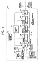
- Fig. 1 is a block diagram showing the configuration of an information processing apparatus 100 of a first embodiment.
- the information processing apparatus 100 serves to embed predetermined digital watermark information into image data.
- the information processing apparatus 100 is provided with image taking means such as a digital camera, a camera-integrated digital video tape recorder or a scanner.
- data entered into an input unit 101 are multi-value image data 106 having a predetermined number of bit per pixel, digital watermark information 107, and embedding parameter information 108 required in embedding the digital watermark information 107.
- the multi-value image data 106 are still image data or moving image data taken by an image pickup unit 112.
- the data are supplied to the input unit in the unit of a predetermined number of image frames.
- the image pickup unit 112 is provided with at least a lens and at least an image pickup device. Utilizing these lens and image pickup device, it converts the optical image of an object into predetermined electrical signals and supplies the input unit 101 with such electrical signals as multi-value image data.
- the digital watermark information 107 contains at least one of copyright information, personal information of the user (for example, name, age, telephone number, e-mail address etc.), information relating to the multi-value image data 106 (for example location of image taking, date and time of image taking, specific comment by the user etc.), information relating to the information processing apparatus 100 (for example maker name, model name etc.), image information including a predetermined mark (for example emblem, logo, stamp etc.) and two-dimensional information for detecting forging. Such information is either stored in advance in a digital watermark generation unit 114 or set by the user in the digital watermark generation unit 114. The content of the digital watermark information 107 is selected according to the object such as protection of copyright, detection of forging or tracing of illegal copy.
- the multi-value image data 106 entered into the input unit 106 are supplied to a wavelet transformation unit 102.
- the digital watermark information 107 and the embedding parameter information 108 entered into the input unit 106 are supplied to a digital watermark embedding unit 103.
- the wavelet transformation unit 102 executes a predetermined transformation process on the multi-value image data supplied from the input unit 101. The detailed functions of the wavelet transformation unit 102 will be explained later.
- Coefficient information (each information being a value generated by frequency analysis) outputted from the wavelet transformation unit 102 is supplied to the digital watermark embedding unit 103.
- the digital watermark embedding unit 103 embeds the digital watermark information 107 in the coefficient information outputted from the wavelet transformation unit 102, utilizing the embedding parameter information 108.
- the detailed functions of the digital watermark embedding unit 103 will be explained later.
- the digital watermark embedding unit 103 supplies an inverse wavelet transformation unit 104 with the coefficient information in which the digital watermark information 107 is embedded. Also the digital watermark embedding unit 103 supplies an output unit 105 with extracting parameter information 109 required for extracting the digital watermark information 107 from the coefficient information.
- the inverse wavelet transformation unit 104 executes a process, corresponding to that of the wavelet transformation unit 102, on the coefficient information supplied from the digital watermark embedding unit 103 and supplies the output unit 105 with thus generated synthesized image data 110.
- the output unit 105 outputs, to the exterior, the synthesized image data 110 in which the digital watermark information 107 is embedded, and the extracting parameter information 109 required for extracting the digital watermark information 107 from the synthesized image data 110.
- the output unit 105 may, for example, execute the output to a bus-type transmission channel through a digital interface based on the IEEE1394 standard.
- the information processing apparatus 100 is provided with a control unit 111 for controlling the functions of various process units in the apparatus 100 and a recording medium 113 storing program codes readable by the control unit 111.
- the recording medium 113 stores program codes for controlling the function of the digital watermark embedding unit 103 and realizing the functions of the first embodiment.
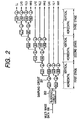
- Fig. 2 is a block diagram showing the configuration of the wavelet transformation unit 102
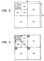
- Fig. 3 is a view showing the concept of sub-bands generated by the wavelet transformation process.
- a blocking circuit 202 in the wavelet transformation unit 102 divides the entered multi-value image data 106 of an image frame into at least a block (or area) of a predetermined size.
- the predetermined size is defined by dividing the multi-value image data 106 of one image frame in the unit of Wb pixels in the lateral direction by Hb pixels in the vertical direction (wherein Wb and Hb are positive integers).
- the wavelet transformation unit 102 executes wavelet transformation in succession on the output of the blocking circuit 202, thereby decomposing the image data into frequency bands (hereinafter called sub bands) of a predetermined number.
- the wavelet transformation unit 102 enters the horizontal component of the above-mentioned block into a low pass filter L1 and a high pass filter H1, and the outputs of the filters are sub-sampled by a sub-sampling circuit 201.
- the wavelet transformation unit 102 enters the vertical component of the multi-value image data 106, processed in succession in the high pass filter H1 and the sub-sampling circuit 201, into a low pass filter L2 and a high pass filter H2, and the outputs of the filters are sub-sampled by the sub-sampling circuit 201.
- the wavelet transformation unit 102 enters the vertical component of the multi-value image data 106, processed in succession in the low pass filter L1 and the sub-sampling circuit 201, into a low pass filter L3 and a high pass filter H3, and the outputs of the filters are sub-sampled by the sub-sampling circuit 201.
- the above-described procedure is taken as a step, and the wavelet transformation unit 102 again executes a procedure similar to the above-mentioned step on the block of which the horizontal component and the vertical component have passed the low pass filter.
- the wavelet transformation unit 102 can decompose at least a block of the predetermined size in succession into plural sub bands.
- the wavelet transformation unit 102 of the present embodiment executes the process of three steps on the multi-value image data 106.
- the size of the block (block size being Wb pixels in the horizontal direction and Hb pixels in the vertical direction) subjected to wavelet transformation by the wavelet transformation unit 102, and the plural sub bands (LL, LH3, HL3, HH3, LH2, HL2, HH2, LH1, HL1, HH1) generated from such block are illustrated in Fig. 3.
- Each sub band in Fig. 3 contains transformation coefficient information (data including a predetermined frequency component) corresponding to the spatial position of the original image.
- a group of coefficient information corresponding to the spatial position same as that in the original image is called a tree.
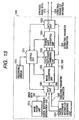
- Fig. 4 shows a tree structure in the wavelet transformation area.
- the wavelet transformation unit 102 executes wavelet transformation on each block, and then supplies the digital watermark embedding unit 103 with plural trees corresponding to a predetermined spatial position.
- Fig. 5 is a block diagram showing the configuration thereof of the first embodiment
- Fig. 6 is a flow chart showing the function thereof.
- the minimum range sub band contains a signal of a very large information amount, while other sub bands contain signals of local and low information amount such as an edge portion or a texture area of the image.
- the user can demolish or erase the digital watermark information by replacing all the coefficient information, contained in the higher sub bands which are assumed to contain the embedded digital watermark information, with zero. Besides, in such case, as the coefficient information contained in the higher sub bands alone are changed, the user can eliminate the digital watermark information, scarcely deteriorating the original image.
- a predetermined signal processing on the image data by the user for the purpose of demolishing or erasing only the digital watermark information contained in such image data with scarce visual deterioration thereof will be called "attack”.
- the present embodiment provides a process for embedding the digital watermark information 107 so as to increase the resistance to the attack by the user while minimizing the influence on the original image signal as far as possible.
- a separating circuit 501 enters, in succession, plural trees (each tree being composed of a group of plural coefficient information corresponding to a predetermined spatial position of each block) contained in each of at least a block (or area) subjected to the wavelet transformation by the wavelet transformation unit 102.
- the separating circuit 501 separates, for each tree supplied from the wavelet transformation unit 102, the coefficient information constituting such tree into a coefficient information contained in the minimum range sub band (LL) and plural coefficient information contained in sub bands other than the minimum one.
- the separating circuit 501 sends the coefficient information contained in the minimum range sub band to a switching circuit 503 and the coefficient information contained in other sub bands to a discriminating circuit 502.
- the discriminating circuit 502 executes a predetermined operation on the plural coefficient information supplied from the separating circuit 501, and determines whether or not to embed the digital watermark information into the coefficient information contained in the minimum range sub band.
- An example of the predetermined operation includes calculating the sum of the absolute values of the coefficient information and comparing the sum with a predetermined threshold value. This process will be explained in more details in the following.
- signals corresponding to the edge portions and texture areas of the image are locally present in sub bands other than the minimum range sub band.
- each tree the sum of the absolute values of the plural coefficient information contained in the sub bands other than the minimum range sub band is anticipated to increase in an edge portion or a texture area of the image.
- a tree in which the sum of the absolute values of the coefficient information contained in the sub bands other than the minimum one increases corresponds to a portion showing a large variation among the edge portions and texture areas of the image, namely a portion of a large variation in the spatial area of the image.
- the digital watermark embedding unit 103 of the first embodiment embeds the digital watermark information into the image, utilizing a property that "the human vision cannot easily detect a small variation in a portion with a large variation in the spatial area". Thus the digital watermark information becomes less detectable to the human eyes.
- the discriminating circuit 502 compares the sum of the absolute values in each tree with a predetermined threshold value and selects, for embedding, the coefficient information contained in the minimum range sub band of a tree for which the threshold value is exceeded. The result of such selection is supplied to switching circuits 503, 505 for controlling the functions of various units.
- the predetermined threshold value is one of the embedding parameter information 108 and becomes a parameter for determining the information amount of the digital watermark information that can be embedded. More specifically, with an increase in the above-mentioned threshold value, the number of the selected trees becomes fewer and the amount of the embeddable information becomes less, while, with a decrease in the threshold value, the number of the selected tree increases and the amount of the embeddable information becomes larger.
- control unit 111 can also adaptively vary the threshold value to be used in the discriminating circuit 502, according to the characteristics of the image data or each block (or area). Thus the control unit 111 can variably control the amount of the embeddable information.
- the predetermined threshold value used in the discriminating circuit 502 is supplied to the exterior, as one of the extracting parameter information 109 required for extracting the digital watermark information 107 from the synthesized image 110.
- the coefficient information contained in the minimum range sub band is supplied through the switching circuit 503 to a quantizing circuit 504.
- the coefficient information contained in the minimum range sub band is supplied to the switching circuit 505.
- the switching circuit 503 is controlled according to the result of discrimination by the discriminating circuit 502.
- the quantizing circuit 504 executes a process of embedding the digital watermark information in succession into the coefficient information contained in the minimum range sub bands of the plural trees selected by the discriminating circuit 502. More specifically, the quantizing circuit 504 executes the embedding for example by quantization.
- the quantization means a process rounding continuous values into linear or non-linear discrete values, or discrete values into linear or non-linear discrete values of a different width.
- a discrete value rounded by such quantization is called a quantization representative value.
- the distance of the discrete values, or the distance of the mutually adjacent quantization representative values, is called a quantization step.
- the quantizing circuit 504 of the present embodiment executes embedding, according to the following embedding rule, of 1-bit information (namely "0" or "1") constituting the digital watermark information 107 into the coefficient information contained in the minimum range sub band of a tree:
- the magnitude of the quantization step is one of the embedding parameter information 108 and corresponds to the intensity of embedding. Stated differently, an increase in the quantization step allows to elevate the resistance to the attack to the synthesized image. Also, based on the relationship between the image quality deterioration and the resistance to the attack, a decrease in the quantization step allows to suppress the deterioration in the quality of the synthesized image.
- control unit 111 can arbitrarily set the value of the quantizing step to be used by the quantizing circuit 504 according to the characteristics of the image block or of each block.
- the above-mentioned value is supplied to the exterior as one of the extracting parameter information 109, required for extracting the digital watermark information 107 from the synthesized image 110.
- the coefficient information subjected to the embedding process in the quantizing circuit 504 is supplied to the switching circuit 505, which supplies a reconstructing circuit 506 with the coefficient information supplied from the switching circuit 503 or from the quantizing circuit 504.
- the function of the switching circuit 505 is controlled by the discriminating circuit 502.
- the reconstructing circuit 506 synthesizes the coefficient information (supplied from the switching circuit 505) contained in the minimum range sub band corresponding to each tree and the coefficient information (supplied from the separating circuit 501) contained in sub bands other than the minimum one to reconstruct the tree structure shown in Fig. 4.
- the output of the reconstructing circuit 506 is supplied, as the output of the digital watermark embedding unit 103, to an inverse wavelet transformation unit 104 for each block.
- the digital watermark information can be embedded into the coefficient information contained in the minimum range sub bands of the blocks, by executing the above-described process to all the trees (step 5607). It is thus rendered possible to increase the resistance to the attack by the user while minimizing the influence on the original image signal as far as possible.
- the separating circuit 501 separates the coefficient information constituting each tree into the coefficient information contained in the minimum range sub band and that contained in other sub bands, but such form is not restrictive.
- the separation may be made into the coefficient information contained in at least a predetermined sub band and that contained in other sub bands.
- the quantizing circuit 504 may embed the digital watermark information 107 into the coefficient information contained in at least a predetermined sub band mentioned above, based on the result of discrimination by the discriminating circuit 502.
- the information determining the embedding position of the digital watermark information 107 (namely the plural coefficient information contained in the sub bands other than the minimum range sub band in each tree) is different from the information in which the digital watermark information 107 is to be embedded (namely the coefficient information contained in the minimum range sub band in each tree).
- the parameter information for determining the information amount of the digital watermark information 107 namely the predetermined threshold value used in the discriminating circuit 501
- the parameter information for determining the level of resistance to the attack or of the image quality deterioration namely the magnitude of the quantization step to be used in the quantizing circuit 504
- the digital watermark information 107 is embedded in the coefficient information contained in the minimum range sub band, the digital watermark information cannot be demolished or erased without significant deterioration of the image quality even in case of an attack.
- the digital watermark embedding unit 103 determines the embedding position of the digital watermark information 107 according to the sum of the absolute values of the plural coefficient information contained in all the sub bands other than the minimum one in each tree, but such form is not restrictive.
- the embedding position can be so determined as to reduce the deterioration in the image quality.
- the digital watermark embedding unit 103 is so constructed as to embed the digital watermark information 107 into the minimum range sub band of each tree, but the embedding position is not limited to the minimum range sub band. It is also possible to adopt such control as to execute the embedding in at least one among the low and middle sub bands.
- the discriminating circuit 502 determines whether or not to embed a part of the digital watermark information 107 into the coefficient information of the above-mentioned predetermined sub band, based on the coefficient information of the sub bands other than the predetermined sub band mentioned above. In this manner it is possible to embed the digital watermark information of a larger information amount so as to reduce the deterioration in the image quality.
- the digital watermark embedding unit 103 of the first embodiment embeds the digital watermark information 107 into the coefficient information of the minimum range sub band of all the trees for which the aforementioned threshold value is exceeded, but the embedding may also be made in certain predetermined trees instead of all the trees.
- Fig. 7A shows a tree 701 constituting the object of embedding and an embeddable area 702, while Figs. 7B and 7C show examples of embedded pattern.
- the embedded pattern is variably set for example according to the information amount of the digital watermark information 107, number of embeddable trees, magnitude of predetermined coefficient information contained in the predetermined sub band, configuration of the two-dimensional information for detecting forging etc.
- the embedded pattern information is supplied, as one of the extracting parameter information 109, to the output unit 105.
- Fig. 8 is a block diagram showing the configuration of an information processing apparatus 800 of the first embodiment, adapted to extract the digital watermark information embedded by the information processing apparatus 100.
- the information processing apparatus 800 is composed for example of a personal computer.
- an input unit 801 receives synthesized image data 110 outputted from the information processing apparatus 100 shown in Fig. 1, and the extracting parameter information 109 required for extracting the digital watermark information 107 embedded in the synthesized image data 110.
- the synthesized image data 110 (containing the embedded digital watermark information 107) entered into the input unit 801 are supplied to a wavelet transformation unit 802. Also the extracting parameter information 109 entered into the input unit 801 are supplied to a digital watermark extracting unit 803.
- the wavelet transformation unit 802 executes, on the synthesized image data supplied from the input unit 801, a process similar to that executed by the aforementioned wavelet transformation unit 102.
- the coefficient information (each coefficient information being generated by frequency analysis) outputted from the wavelet transformation unit 802 are supplied to the digital watermark extracting unit 803.
- the digital watermark extracting unit 803 extracts the digital watermark information 107 embedded in the coefficient information outputted from the wavelet transformation unit 802. The detailed functions of the digital watermark extracting unit 803 will be explained later.
- the digital watermark information 107 extracted in the digital watermark extracting unit 803 is supplied to a display unit 705. Also the coefficient information after the extraction of the digital watermark information 107 is supplied to an inverse wavelet transformation unit 804, which executes a process similar to that executed by the aforementioned inverse wavelet transformation unit 104.
- Data transformed into the original image data in the inverse wavelet transformation unit 804 are supplied to the display unit 805.
- the display unit 805 can synthesize the image data and the displayable digital watermark information 107 which has been embedded therein and visually display these data on a same image screen.
- an alarm signal generated by a control unit 806 may be displayed in superposition with the image data.
- the information processing apparatus 800 may be provided with a printing unit in addition to the display unit.
- the printing unit synthesizes and prints the image data and the displayable digital watermark information 107 that has been embedded therein on a same image field. Also, in case a forging is detected, the printing unit synthesizes and prints the image data and the alarm signal, generated by the control unit 806, on a same image field.
- the information processing apparatus 800 is provided with a control unit 806 for controlling the functions of various process units and a recording medium 807 for storing program codes readable by the control unit 806.
- the recording medium 807 stores program code that realize the functions of the first embodiment by controlling the functions of the digital watermark extracting unit 803.
- the synthesized image data 110 obtained by dividing into one or more blocks and executing the wavelet transformation for each block, are supplied from the wavelet transformation unit 802 to a separating circuit 901.
- the separating circuit 901 separates, in each of plural trees contained in each block, the coefficient information constituting such tree into the coefficient information contained in the minimum range sub band (LL) and the plural coefficient information contained in other sub bands.
- the separating circuit 901 sends the coefficient information contained in the minimum range sub band to a switching circuit 903 and the coefficient information contained in the sub bands other than the minimum one to a discriminating circuit 902.
- the discriminating circuit 902 executes, for each tree, a predetermined operation on the plural coefficient information supplied from the separating circuit 901, thereby discriminating whether the coefficient information contained in the minimum range sub band contains the digital watermark information 107.
- the discriminating circuit 902 executes an operation corresponding to the discriminating circuit 502 provided in the digital watermark embedding unit 103. More specifically, for each tree, it calculates the sum of the absolute values of the plural coefficient information contained in the sub bands other than the minimum one and compares the result of such operation with a predetermined threshold value (contained in the extracting parameter information 109).
- the discriminating circuit 902 compares the sum of the absolute values in each tree with the predetermined threshold value, and judges that the digital watermark information 107 is embedded in the coefficient information contained in the minimum range sub band of a tree for which such threshold value is exceeded. The result of discrimination is supplied to a switching circuit 903 and controls the function thereof.
- the discriminating circuit 902 specifies the embedded pattern utilizing the embedding parameter information contained in the extracting parameter information 109, and controls the switching circuit 903 according to the specified result.
- the coefficient information contained in the minimum range sub band in a tree for which the threshold value is exceeded is supplied, through the switching circuit 903, to a bit judging circuit 904.
- the coefficient information contained in the minimum range sub band in a tree for which the threshold value is not exceeded is supplied, through the switching circuit 903, to a reconstructing circuit 905.
- the bit judging circuit 904 executes a calculation on the coefficient information (contained in the minimum range sub band) supplied through the switching circuit 903, and, based on the result of calculation, detects the 1-bit information constituting the digital watermark information 107.
- bit judging circuit 904 divides the entered coefficient information by the corresponding quantizing step to determine a quantizing index, and judges the embedded bit information according to the following rules, utilizing thus determined quantizing index:
- the bit judging circuit 904 can extract all the bit train constituting the digital watermark information 107.
- the bit judging circuit 904 supplies the control unit 806 with the digital watermark information extracted from each block.
- the bit judging circuit 904 judges the forging of the synthesized image data 110, utilizing such digital watermark information. The result of judgment is supplied to the control unit 806 and is displayed on the display unit 805 when necessitated.
- the method for detecting the forging of the synthesized image data 110 is not limited to the process mentioned above.
- the digital watermark extracting unit 803 can also detect the forging by holding in advance the digital watermark information 107 embedded in the synthesized image data 110 and comparing it with the result of extraction by the bit judging circuit 904.
- the coefficient information after extraction of the digital watermark information 107 in the bit judging circuit 904 is supplied to the reconstructing circuit 905.
- the reconstructing circuit 905 reconstructs the tree structure shown in Fig. 4 by synthesizing the coefficient information (supplied from the switching circuit 903 or the bit judging circuit 904) contained in the minimum range sub band corresponding to each tree and the coefficient information (supplied from the separating circuit 901) contained in the sub bands other than the minimum one.
- the output of the reconstructing circuit 905 is supplied, as the output of the digital watermark extracting unit 903, for each block, to the inverse wavelet transformation unit 804.
- the information determining the embedding position of the digital watermark information (namely the plural coefficient information contained in the sub bands other than the minimum one) is different from the information in which the digital watermark information itself is embedded (namely the coefficient information contained in the minimum range sub band in each tree).
- the embedding process utilizing such plural different information allows to increase the freedom of embedding process. Also it is rendered possible to embed the digital watermark information while maintaining the feature of the information for determining the embedding position.
- the parameter information determining the information amount of the digital watermark information namely the predetermined threshold value to be used in the discriminating circuit 502
- the parameter information determining the resistance to the attack or the level of image quality deterioration namely the magnitude of the quantizing step to be used in the quantizing circuit 504. It is therefore possible to arbitrary select the balance of the resistance of the digital watermark information of the predetermined information amount and the quality of the synthesized image.
- the first embodiment has provided a configuration which, giving emphasis in increasing the resistance of the synthesized image containing the embedded digital watermark information against attack, determines the embedding position of the digital watermark information based on the coefficient information contained in the sub bands other than the minimum range sub band and embeds the digital watermark information 107 in the coefficient information contained in the minimum range sub band.
- the second embodiment provides a configuration of determining the embedding position of the digital watermark information utilizing the coefficient information contained in the minimum range sub band and embedding the digital watermark information in the plural coefficient information contained in the sub bands other than the minimum one.
- the digital watermark embedding unit 103 shown in Fig. 1 has a configuration different from that in the first embodiment.
- the explanation will be given only to the process unit different from the first embodiment (namely the digital watermark embedding unit), while other process units are same as those in the first embodiment and will not be explained further.
- Fig. 10 is a block diagram showing the detailed configuration of a digital watermark embedding unit 1000 in the second embodiment, and Fig. 11 is a flow chart showing the function thereof.
- a separating circuit 1001 enters, in succession, plural trees (each tree being composed of a group of plural coefficient information corresponding to plural sub bands) contained in each of one or more blocks (or areas) subjected to the wavelet transformation in the wavelet transformation unit 102.
- the separating circuit 1001 separates the plural coefficient information constituting each tree into the coefficient information contained in the minimum range sub band (LL) and the plural coefficient information contained in the sub bands other than the minimum one.
- the separating circuit 1001 sends the coefficient information contained in the minimum range sub band to the discriminating circuit 1002 and the plural coefficient information contained in other sub bands to a quantizing circuit 1003.
- the discriminating circuit 1002 discriminates whether or not to embed the digital watermark information 107, utilizing the coefficient information contained in the minimum range sub band, and embeds the watermark information in the coefficient information not contained in the minimum range sub band.
- the discriminating circuit 1002 determines the embedding position of the digital watermark information by generating a histogram of the coefficient information contained in the minimum range sub band and dividing these coefficients based on such histogram.
- the function of the discriminating circuit 1002 will be explained in the following.
- the coefficient information contained in the minimum range sub band in each tree will be represented as x_i, wherein i is a natural number assigned to each coefficient information contained in the minimum range sub band.
- information indicating the above-mentioned predetermined range is one of the information contained in the embedding parameter information 108.
- the value L defining the above-mentioned predetermined range is a parameter influencing the number of the coefficient information x_i to be embedded and also determining the information amount of the embeddable digital watermark information.
- the discriminating circuit 1102 pays attention only to x_i satisfying a condition a_j ⁇ x_i ⁇ a_j + L. Then it selects a tree corresponding to at least a coefficient information x_i selected by the above-mentioned condition, and recognizes the coefficient information constituting each tree and not contained in the minimum range sub band (namely plural coefficient information other than x_i) as the object of embedding.
- the result of such recognition namely the information designating the tree for embedding is supplied to a quantizing circuit 1003. Also the predetermined range used in the discriminating circuit 1002 is supplied to the exterior, as one of the extracting parameter information 109 required for extracting the digital watermark information 107 from the synthesized image 110.
- control unit 111 can also adaptively vary the predetermined range to be used by the discriminating circuit 1002, according to the feature of the image data or of the blocks.
- control unit 111 can variably control the embeddable information amount.
- the quantizing circuit 903 embeds a bit train of at least a bit, constituting the digital watermark information 107, into one or more coefficient information contained in the tree recognized as the object of embedding (namely coefficient information other than x_i in each tree).
- the quantizing circuit 1003 embeds 1-bit information into the coefficient information constituting the object of embedding, by a method similar to that employed by the quantizing circuit 504 in the first embodiment, namely by the quantization method.
- the magnitude of the quantizing step controlling the embedding process by the quantization method, is one of the embedding parameter information 108.
- Such magnitude of the quantizing step is a parameter including the image quality, the deterioration in the quality of the synthesized image can be suppressed by decreasing the magnitude of the quantizing step. Such decrease in the magnitude of the quantizing step reduces the resistance, based on the relationship between the image quality and the resistance.
- control unit 111 can arbitrarily set the quantizing step to be used in the quantizing circuit 1003, according to the feature of the image data or the blocks.
- the value of the quantizing step used in the quantizing circuit 1003 is supplied to the exterior, as one of the extracting parameter information 109 required for extracting the digital watermark information 107 from the synthesized image data 110.
- the quantizing circuit 1003 selects, according to a predetermined method, the coefficient information in which the watermark information is to be actually embedded, from one or more coefficient information contained in a tree.
- the 1-bit information may be embedded in the n-th largest one among the absolute values of one or more coefficient information contained in each tree, based on the output n of a random number generator provided in the quantizing circuit 1003, wherein n is a random natural number outputted by the random number generator.
- the coefficient information subjected to the embedding process in the quantizing circuit 1003 is supplied to a reconstructing circuit 1004.
- a reconstructing circuit 1004 synthesizes the coefficient information (supplied from the separating circuit 1001) contained in the minimum range sub band corresponding to each tree and the coefficient information (supplied from the quantizing circuit 1003) contained in the sub bands other than the minimum one to reconstruct the tree structure shown in Fig. 4.
- the output of the reconstructing circuit 1004 is supplied, as the output of the digital watermark embedding unit 1000, for each block, to an inverse wavelet transformation circuit 104.
- the digital watermark information 107 can be embedded in the coefficient information contained in the sub bands other than the minimum one in each tree (step S1107). It is thus rendered possible to minimize the deterioration in the image quality of the original image and to elevate the resistance against the attack by the user as far as possible.
- the information determining the embedding position of the digital watermark information 107 is different from the information in which the digital watermark information 107 itself is to be embedded (namely the plural coefficient information contained in the sub bands other than the minimum range sub band in each tree).
- the parameter information determining the information amount of the digital watermark information 107 namely the predetermined range to be used in the discriminating circuit 1002
- the parameter information determining the resistance against attack or the level of image quality deterioration namely the magnitude of the quantizing step to be used in the quantizing circuit 1003.
- the digital watermark embedding unit 1000 of the second embodiment so controls as to select all the coefficient information contained in the sub bands other than the minimum range sub band in each tree as the object of embedding, but such form is not restrictive. It is also possible to select plural sub bands, contained in the middle and high range sub bands, as the object of embedding.
- the digital watermark embedding unit 1000 of the second embodiment so controls as to embed the digital watermark information in all the trees recognized as the object of embedding, but it is also possible, as in the first embodiment, to execute embedding in predetermined trees instead of all the trees.
- the embedded pattern is variably selected according to the information amount of the digital watermark information 107, number of trees in which the embedding is possible, magnitude of the predetermined coefficient information in the predetermined sub bands contained in the tree in which embedding is possible, magnitude of the coefficient information contained in the sub band constituting the object of embedding, structure of the two-dimensional information for detecting forging etc.
- the embedding pattern information is supplied, as one of the extracting parameter information 109, to the output unit 105.
- the digital watermark embedding unit 803 shown in Fig. 8 has a configuration different from that in the first embodiment.
- the explanation will be given only to the process unit different from the first embodiment (namely the digital watermark embedding unit), while other process units are same as those in the first embodiment and will not be explained further.
- Fig. 12 is a block diagram showing the detailed configuration of a digital watermark extracting unit 1200 in the second embodiment.
- the synthesized image data 110 obtained by division into one or more blocks and by wavelet transformation for each block are supplied from the wavelet transformation unit 802 to a separating circuit 1201.
- the separating circuit 1201 separates, for each of the plural trees contained in each block, the coefficient information constituting the tree into the coefficient information-contained in the minimum range sub band (LL) and the plural coefficient information contained in the sub bands other than the minimum one.
- the separating circuit 1201 sends the coefficient information contained in the minimum range sub band to a discriminating circuit 1202, and the coefficient information contained in other sub bands to a bit judging circuit 1203.
- the discriminating circuit 1202 discriminates, utilizing information indicating a predetermined range contained in the extracting parameter information 109, whether the coefficient information contained in the minimum range sub band of each tree is within the above-mentioned predetermined range.
- the discriminating circuit 1202 judges that the digital watermark information 107 is contained in the plural coefficient information other than that in the minimum range sub band, contained in the tree of which the above-mentioned coefficient information is within the predetermined range.
- the discriminating circuit 1202 controls the function of a bit judging circuit 1203.
- the bit judging circuit 1203 executes an operation on the coefficient information (plural coefficient information contained in the sub bands other than the minimum one) supplied from the separating circuit 1201, utilizing the magnitude of the quantizing step contained in the extracting parameter information 109, and detects n-bit information constituting the digital watermark information 107 based on the result of such operation.
- the bit judging circuit 1203 determines the quantizing index by dividing the entered plural coefficient information with the corresponding quantizing step. Utilizing thus determined quantizing step, the bit judging circuit 1203 judges the embedded bit information according to the following rule:
- the bit judging circuit 1203 can extract all the bit train constituting the digital watermark information 107.
- the bit judging circuit 1203 supplies the control unit 806 with the digital watermark information extracted from each block.
- the bit judging circuit 1203 judges the forging of the synthesized image data 110, utilizing such digital watermark information. The result of judgment is supplied to the control unit 806 and displayed on the display unit 805 when necessitated.
- the method of detecting forging of the synthesized image data 110 is however not limited to that described above. It is also possible to detect forging, for example, by a configuration in which the digital watermark extracting unit 1200 in advance holds the digital watermark information embedded in the synthesized image data 110 and compares it with the result of extraction by the bit judging circuit 1203.
- the coefficient information of each tree from which the digital watermark information is extracted by the bit judging circuit 1203 are supplied to a reconstructing circuit 1204.
- the reconstructing circuit 1204 reconstructs the tree structure shown in Fig. 4 by synthesizing the coefficient information (supplied from the separating circuit 1201) contained in the minimum range sub band corresponding to each tree and the coefficient information (supplied from the bit judging circuit 1203) contained in the sub bands other than the minimum one.
- the output of the reconstructing circuit 1204 is supplied, as the output of the digital watermark extracting unit 1200, for each block, to the inverse wavelet transformation unit 804.
- the information determining the embedding position of the digital watermark information (namely the coefficient information contained in the minimum range sub band) is different from the information in which the digital watermark information itself is embedded (namely the plural coefficient information contained in the sub bands other the minimum one).
- the embedding process utilizing such plural different information allows to increase the freedom of embedding process. Also it is rendered possible to embed the digital watermark information while maintaining the feature of the information for determining the embedding position.
- the parameter information determining the information amount of the digital watermark information namely the predetermined range to be used in the discriminating circuit 1002
- the parameter information determining the resistance to the attack or the level of image quality deterioration namely the magnitude of the quantizing step to be used in the quantizing circuit 1003
- the first and second embodiments have disclosed configurations for dividing the multi-value image data 106 of an image field into one or more blocks (for areas of predetermined sizes), executing wavelet transformation on each block, and embedding the digital watermark information 107, in the wavelet transformed area, in the predetermined coefficient information contained in the blocks.
- the third embodiment provides a configuration of dividing the multi-value color image data of an image field into information signals of one or more kinds, and embedding the digital watermark information in at least one of such information signals.
- Fig. 13 is a block diagram showing the configuration of an information processing apparatus 1300 of the third embodiment, adapted to embed predetermined digital watermark information 1307 into multi-value color image data 1306.
- the information processing apparatus 1300 is provided with image pickup means such as a digital camera, a camera-integrated video tape recorder or a scanner.
- data received by an input unit 1301 include multi-value color image data 1306 including red, green and blue components in each pixel, digital watermark information 1307, and embedding parameter information 1308 required in embedding the digital watermark information 1307.
- the multi-value color image data 1306 are still image data or moving image data taken by an image pickup unit 1312.
- the data are supplied to the input unit 1312 in the unit of a predetermined number of image fields.
- the image pickup unit 1312 is provided at least a lens and at least an image pickup element, converts the optical image of an object into plural electrical signals including red, green and blue components utilizing these and supplies the input unit 1301 with such electrical signals as multi-value color image data.
- the digital watermark information 1307 contains at least one of the copyright information, personal information of the user (for example name, age, telephone number or e-mail address), information on the multi-value color image data (for example location of image taking, date and time of image taking or specific comment by the user), information on the information processing apparatus 1300 (for example maker name or model name), image information including a predetermined mark (for example emblem, logo or stamp) and two-dimensional information for detecting forging (for example a point-symmetrical or line-symmetrical mark).
- personal information of the user for example name, age, telephone number or e-mail address
- information on the multi-value color image data for example location of image taking, date and time of image taking or specific comment by the user
- information on the information processing apparatus 1300 for example maker name or model name
- image information including a predetermined mark for example emblem, logo or stamp
- two-dimensional information for detecting forging for example a point-symmetrical or line-symmetrical mark
- the multi-value color image data 1306 entered into the input unit 1301 are supplied to an image conversion unit 1302. Also the digital watermark information 1307 and the embedding parameter information 1308 entered into the input unit 1301 are supplied to a digital watermark embedding unit 1303.
- the image conversion unit 1302 converts the multi-value color image data, supplied from the input unit 1301, into plural signal components which are composed of a luminance signal component and two color difference signal components.
- the image conversion unit 1302 executes sampling of the color difference signal components Cr, Cb when necessitated, thereby achieving conversion to color difference signal components Cr, Cb in the unit of N pixels (N being an integer larger than 1).
- the plural signal components (luminance signal component Y and two color difference signal components Cr, Cb) outputted from the image conversion unit 1302 are supplied to the digital watermark embedding unit 1303.
- the digital watermark embedding unit 1303 embeds the digital watermark information 1307 into at least one signal component outputted from the image conversion unit 102, utilizing the embedding parameter information 1308.
- the detailed functions of the digital watermark embedding unit 1303 will be explained later.
- the digital watermark embedding unit 1303 supplies an inverse image conversion unit 1304 with the plural signal components of which a part contains the embedded digital watermark information 1307.
- the digital watermark embedding unit 1303 also supplies an output unit 1305 with the extracting parameter information 1309, required for extracting the digital watermark information 1307 from the above-mentioned signal components.
- the inverse image conversion unit 1304 executes a process corresponding to the conversion process of the image conversion unit 1302, on the plural signal components supplied from the digital watermark embedding unit 1303, and sends the resulting synthesized image data 1310 to the output unit 1305.
- the output unit 1305 outputs, to the exterior, the synthesized image data 1310 containing the embedded digital watermark information 1307 and the extracting parameter information 1309 required for extracting the digital watermark information 1307 from the synthesized image data 1310.
- the output unit 1305 may execute the output for example to a bus-type transmission channel through a digital interface based on the IEEE1394 standard, or to a wireless transmission channel through a wireless interface of an infrared communication method.
- the information processing apparatus 1300 is provided with a control unit 1311 for controlling the functions of various process unit provided in the apparatus and a recording medium 1313 for storing program codes readable by the control unit 1311.
- Fig. 14 is a block diagram showing the configuration of the digital watermark embedding unit 1303 of the third embodiment
- Fig. 15 is a flow chart showing the functions thereof.
- the color difference signal components In a natural image, the color difference signal components generally have a larger redundancy in comparison with the luminance signal component. The image quality is not much influenced visually even if the digital watermark information including a specified bit train is embedded in the redundant portion of such color difference signal components.
- the digital watermark embedding unit 1303 determines, utilizing the luminance signal component Y, the spatial area in which the digital watermark information 1307 is to be embedded, and embeds the digital watermark information 1307 in the two color difference signal components Cr, Cb corresponding to thus determined spatial area.
- a step S1501 among the plural signal components supplied from the image conversion unit 1302, the luminance signal component Y is supplied to a discriminating circuit 1401 while the two color difference signal components Cr, Cb are supplied to a switching circuit 1402.
- the discriminating circuit 1401 discriminates whether the luminance signal component Y of a pixel exceeds a predetermined threshold value, and recognizes the color difference signal components corresponding to the luminance signal component Y exceeding such threshold value, as the objects of embedding. There may also be adopted a process that the discriminating circuit 1401 discriminates whether the luminance signal component Y is within a predetermined range and recognizes the color difference signal components, corresponding to the luminance signal component Y within such predetermined range, as the object of embedding.
- the above-mentioned predetermined threshold value or range is supplied to the discriminating circuit 1401, as one of the embedding parameter information 1308, and is a parameter information determining the information amount of the digital watermark information 1307. Also, the predetermined threshold value or range used in the discriminating circuit 1401 is supplied to the exterior, as one of the extracting parameter information 1309 required for extracting the digital watermark information 1307 from the synthesized image data 1310.
- the control unit 1313 of the third embodiment can arbitrarily set the predetermined threshold value or range mentioned above, according to the feature of the image data.
- the result of discrimination by the discriminating circuit 1401 is supplied to switching circuits 1404, 1402 and controls the functions thereof.
- the luminance signal component Y, processed in the discriminating circuit 1401, is supplied to the inverse image conversion unit 1304.
- the switching circuit 1402 sends the color difference signal components Cr, Cb corresponding to the luminance signal component Y recognized as the object of embedding to a quantizing circuit 1403, and sends other color difference signal components Cr, Cb to a switching circuit 1404.
- the quantizing circuit 1403 is so constructed as to embed, in a step S1504, the digital watermark information 1307 of a bit into the color difference signal components of a unit, thereby embedding the digital watermark information 1307 of at least a bit in the color difference signal components Cr, Cb in total.
- the quantizing circuit 1403 embeds the information of a bit into the color difference signal components Cr, Cb constituting the objects of embedding by a method similar to that employed by the quantizing circuit 504 in the first embodiment, namely by quantization.
- the magnitude of the quantizing step controlling the embedding process of the quantizing circuit 1403 is one of the information contained in the embedding parameter information 1308.
- the magnitude of this quantizing step is a parameter influencing the image quality, and a decrease of the quantizing step allows to suppress the deterioration of the synthesized image data 1310. However, a decrease in the quantizing step reduces the resistance, because of the relationship between the image quality and the resistance.
- control unit 1313 can arbitrarily set the value of the quantizing step to be used by the quantizing circuit 1403, according to the characteristics of the image data. Furthermore, the quantizing step used in the quantizing circuit 1403 is supplied to the exterior, as one of the extracting parameter information 109 required for extracting the digital watermark information 1307 from the synthesized image data 1310.
- step S1505 By executing the above-described process on all the luminance component signals Y, it is rendered possible to embed the digital watermark information 107 of at least 1 bit into all the color difference component signals Cr, Cb (step S1505).
- the color difference signal components Cr, Cb subjected to embedding process in the quantizing circuit 1403 are supplied to the inverse image conversion unit 1304.
- the information determining the embedding position (namely the luminance signal component Y) is different from the information in which the digital watermark information itself is embedded (namely the color difference signal components Cr, Cb).
- the embedding process utilizing the presence of information of such plural kinds allows to increase the freedom of embedding process. Also it is rendered possible to embed the digital watermark information while securely maintaining the feature of the information for determining the embedding method and position.
- the third embodiment it is possible to independently set the parameter information determining the information amount of the digital watermark information (namely the predetermined threshold value or range to be used in the discriminating circuit 1402) and the parameter information determining the resistance to the attack or the level of image quality deterioration (namely the magnitude of the quantizing step to be used in the quantizing circuit 1403). It is therefore possible to arbitrarily select the balance of the resistance of the digital watermark information of the predetermined information amount and the quality of the synthesized image.
- the parameter information determining the information amount of the digital watermark information namely the predetermined threshold value or range to be used in the discriminating circuit 1402
- the parameter information determining the resistance to the attack or the level of image quality deterioration namely the magnitude of the quantizing step to be used in the quantizing circuit 1403
- the embedding can be achieved without almost any visual deterioration of the original image.
- the quantizing circuit 1403 directly manipulates the luminance signal component Y and the color difference signal components Cr, Cb to embed the digital watermark information 1307 into the spatial area of the color difference signal components Cr, Cb, but such configuration is not restrictive.
- the quantizing circuit 1403 may embed the digital watermark information 1307 into predetermined frequency ranges of the color difference signal components Cr, Cb based on the orthogonally transformed luminance signal component Y.
- the digital watermark embedding unit 1303 recognizes, as the object of embedding, all the color difference signal components Cr, Cb corresponding to the luminance signal component Y exceeding the aforementioned predetermined threshold value, but the embedding may also be conducted, as in the first embodiment, in the color difference signal components Cr, Cb corresponding to a predetermined luminance signal component Y.
- the embedded pattern mentioned above is variably set for example according to the information amount of the digital watermark information 1307, number of embeddable trees, magnitude of the predetermined coefficient information contained in a predetermined sub band, configuration of the two-dimensional information for detecting forging etc.
- the embedding pattern information is supplied, as one of the extracting parameter information 1309, to the output unit 1305.
- the third embodiment executes a process of determining the embedding position based on the luminance signal component Y and embedding the digital watermark information 1307 into the color difference signal components Cr, Cb corresponding to such embedding position, but such process is not restrictive.
- the third embodiment converts the red, green and blue components R, G, B supplied from the image pickup unit 1312 into the luminance signal component Y and the color difference signal components Cr, Cb, but such form is not restrictive.
- the digital watermark information 1307 into at least one of the red, green and blue components R, G, B without conversion into the luminance signal component Y and the color difference signal components Cr, Cb.
- the information processing apparatus for extracting the digital watermark information 1307 embedded in the synthesized image data 1310 can for example be constructed similar to the information processing apparatus 800 shown in the first and second embodiments.
- the digital watermark extracting unit 803 separates the luminance signal component Y and the color difference signal components Cr, Cb, and discriminates the color difference signal components Cr, Cb in which the digital watermark information 1307 is embedded, utilizing the luminance signal component Y and the extracting parameter information 1309. Then, utilizing the result of such discrimination, the digital watermark extracting unit 803 extracts the digital watermark information 1307 from the color difference signal components Cr, Cb.
- control unit 111, 806, 1311 (including a microcomputer) of the system or apparatus of the foregoing embodiments, with a recording medium 113, 807, 1313 recording the program codes of a software realizing the functions of the foregoing embodiments.
- control unit 111, 806, 1311 of the system or apparatus of the foregoing embodiments reads the program codes stored in the recording medium 113, 807, 1313 and controls the function of the apparatus or system so as to realize the functions of the foregoing embodiments.
- a recording medium 113 or 1313 storing the program codes realizing the process and function of the first embodiment shown in Fig. 6, second embodiment shown in Fig. 11 or third embodiment shown in Fig. 15 is supplied to the control unit 111 or 1311 shown in Fig. 1 or 13.
- the control unit 111 or 1311 itself reads the program codes stored in such recording medium 113 or 1313 and controls the various process circuits of the information processing apparatus 100 or 1300, shown in Fig. 1 or 13, so as to realize the functions of the above-mentioned embodiments.
- the program codes themselves read from the recording medium 113 or 1313 realize the functions of the aforementioned embodiments, and such recording medium storing the program codes constitutes a part of the present invention.
- the recording medium 113, 807 or 1313 for supplying the program codes can be, for example, a floppy disk, a hard disk, an optical disk, a magnetooptical disk, a CD-ROM , a CD-R, a magnetic tape, a non-volatile memory card or a ROM.
- the present invention also includes a case where an operating system or an application software functioning on the control unit 111, 806 or 1311 controls the function of the system or apparatus of the aforementioned embodiments under the instruction of the program codes read from the recording medium 113, 807 or 1313, thereby realizing the functions of the aforementioned embodiments.
- the present invention further includes a case wherein the program codes read from the recording medium 113, 807 or 1313 are once stored in a memory provided in a function expansion board or a function expansion unit connected to the control unit 111, 806 or 1311, and a control unit provided in the function expansion board or the function expansion unit controls the function of the system or apparatus of the foregoing embodiments under the instruction of the program codes, thereby realizing the functions of the aforementioned embodiments.
- the present invention may be embodied in various forms without departing from the principal character thereof.
- the multi-value image data 10 are subjected to the wavelet transformation and the digital watermark information 107 is embedded in the coefficient information obtained therefrom, but such control is not restrictive.
- the multi-value image data 106 are divided into one or more blocks and the digital watermark information 107 is embedded in each block, but such control is not restrictive.
- the embedding position is determined by a predetermined signal component constituting the image data and the digital watermark information is embedded in a signal component different from the predetermined signal component, but such control is not restrictive and a similar process may be applied to audio data or text data.
- the information processing apparatus 800 or 1300 of the first to third embodiments has been explained by a configuration integrated with the image pickup unit 112 or 1312, but such configuration is not restrictive. It is also possible to provide the input unit 101, 1301 of the information processing apparatus 100, 1300 with an external terminal and to enter a still or moving image taken by an external image pickup unit 112 or 1312.
- the present invention allows to efficiently control the method of embedding or extracting the digital watermark information into or from digital information. It is also rendered possible, utilizing a fact that the digital information have components of different kinds, to individually manage the digital watermark information and the information indicating the method of embedding (or extracting) such digital watermark information.
- the present invention embeds the digital watermark information in a signal component different from the signal component for determining the embedding position of the digital watermark information, thereby increasing the freedom of the embedding process and thus realizing an embedding process of a higher resistance or a less deterioration.
- the present invention also allows embedding of the digital watermark information without erasing or exaggerating the feature of the information determining the embedding position.
- the present invention can be carried out using a multi-purpose computer suitably programmed.
- the present invention can be implemented by a computer program which can be stored on a storage medium or transmitted as a signal e.g. down loaded over a network such as the internet.
Priority Applications (1)
| Application Number | Priority Date | Filing Date | Title |
|---|---|---|---|
| EP20050077421 EP1617643B1 (en) | 1998-06-24 | 1999-06-24 | Information processing apparatus, method and memory medium therefor |
Applications Claiming Priority (2)
| Application Number | Priority Date | Filing Date | Title |
|---|---|---|---|
| JP17712898 | 1998-06-24 | ||
| JP17712898A JP4026933B2 (ja) | 1998-06-24 | 1998-06-24 | 情報処理装置及び方法並びに記録媒体 |
Related Child Applications (1)
| Application Number | Title | Priority Date | Filing Date |
|---|---|---|---|
| EP20050077421 Division EP1617643B1 (en) | 1998-06-24 | 1999-06-24 | Information processing apparatus, method and memory medium therefor |
Publications (3)
| Publication Number | Publication Date |
|---|---|
| EP0967783A2 EP0967783A2 (en) | 1999-12-29 |
| EP0967783A3 EP0967783A3 (en) | 2000-11-15 |
| EP0967783B1 true EP0967783B1 (en) | 2006-04-19 |
Family
ID=16025670
Family Applications (2)
| Application Number | Title | Priority Date | Filing Date |
|---|---|---|---|
| EP19990304976 Expired - Lifetime EP0967783B1 (en) | 1998-06-24 | 1999-06-24 | Information processing apparatus, method and memory medium therefor |
| EP20050077421 Expired - Lifetime EP1617643B1 (en) | 1998-06-24 | 1999-06-24 | Information processing apparatus, method and memory medium therefor |
Family Applications After (1)
| Application Number | Title | Priority Date | Filing Date |
|---|---|---|---|
| EP20050077421 Expired - Lifetime EP1617643B1 (en) | 1998-06-24 | 1999-06-24 | Information processing apparatus, method and memory medium therefor |
Country Status (5)
| Country | Link |
|---|---|
| US (1) | US6535616B1 (zh) |
| EP (2) | EP0967783B1 (zh) |
| JP (1) | JP4026933B2 (zh) |
| CN (1) | CN1168010C (zh) |
| DE (2) | DE69930896T2 (zh) |
Cited By (1)
| Publication number | Priority date | Publication date | Assignee | Title |
|---|---|---|---|---|
| CN1592917B (zh) * | 2001-11-23 | 2012-09-05 | 塞沃路森公司 | 水印嵌入 |
Families Citing this family (59)
| Publication number | Priority date | Publication date | Assignee | Title |
|---|---|---|---|---|
| US6785814B1 (en) * | 1998-07-28 | 2004-08-31 | Fuji Photo Film Co., Ltd | Information embedding method and apparatus |
| US6944313B1 (en) | 1998-08-06 | 2005-09-13 | Canon Kabushiki Kaisha | Method and device for inserting and decoding a watermark in digital data |
| JP3472188B2 (ja) * | 1999-03-31 | 2003-12-02 | キヤノン株式会社 | 情報処理システム、情報処理装置、情報処理方法及び記憶媒体 |
| JP2001016435A (ja) * | 1999-06-30 | 2001-01-19 | Minolta Co Ltd | 画像形成装置 |
| US7006257B1 (en) * | 1999-11-19 | 2006-02-28 | Canon Kabushiki Kaisha | Image processing apparatus, image processing method, and storage medium |
| JP3599621B2 (ja) * | 1999-11-19 | 2004-12-08 | キヤノン株式会社 | 画像処理装置、画像処理方法及び記憶媒体 |
| FR2803710B1 (fr) | 2000-01-11 | 2002-03-22 | Canon Kk | Procede et dispositif d'insertion d'un signal de marquage dans une image |
| US6801636B2 (en) * | 2000-01-31 | 2004-10-05 | Canon Kabushiki Kaisha | Image processing apparatus and method, and storage medium |
| JP4098455B2 (ja) * | 2000-03-10 | 2008-06-11 | 株式会社日立製作所 | マーク画像中の電子透かし情報の参照方法及び計算機 |
| TW538636B (en) | 2000-09-01 | 2003-06-21 | Matsushita Electric Ind Co Ltd | Reproduction equipment, reproduction equipment specifying equipment, reproduction equipment specifying system and methods and recording media for said equipment and system |
| KR100359506B1 (ko) * | 2000-09-09 | 2002-11-04 | 주식회사 마크애니 | 디지털 영상 워터마킹 장치 및 방법 |
| JP2002093047A (ja) * | 2000-09-20 | 2002-03-29 | Sony Corp | データ記録媒体、データ記録装置および方法、データ出力装置および方法、データ表示方法、コンテンツデータ並びにデータ再生装置および方法 |
| GB2369947A (en) * | 2000-12-07 | 2002-06-12 | Sony Uk Ltd | Embedding data in fields of an image |
| GB2369950B (en) * | 2000-12-07 | 2005-03-16 | Sony Uk Ltd | Image processing apparatus |
| KR100355033B1 (ko) * | 2000-12-30 | 2002-10-19 | 주식회사 실트로닉 테크놀로지 | 선형예측 분석을 이용한 워터마크 삽입/추출 장치 및 그방법 |
| EP1231767B1 (en) * | 2001-02-09 | 2011-04-13 | Canon Kabushiki Kaisha | Information processing apparatus and its control method, computer program, and storage medium |
| JP2002325170A (ja) * | 2001-04-24 | 2002-11-08 | Canon Inc | 画像処理装置及びその方法並びにプログラムコード、記憶媒体 |
| US7006656B2 (en) * | 2001-10-15 | 2006-02-28 | The Research Foundation Of Suny | Lossless embedding of data in digital objects |
| JP3937841B2 (ja) * | 2002-01-10 | 2007-06-27 | キヤノン株式会社 | 情報処理装置及びその制御方法 |
| JP4107851B2 (ja) | 2002-02-13 | 2008-06-25 | 三洋電機株式会社 | 電子透かし埋め込み方法およびその方法を利用可能な符号化装置と復号装置 |
| JP4072448B2 (ja) * | 2002-03-14 | 2008-04-09 | キヤノン株式会社 | 電子透かし抽出方法及び装置及びプログラム及び記憶媒体 |
| US20030210803A1 (en) * | 2002-03-29 | 2003-11-13 | Canon Kabushiki Kaisha | Image processing apparatus and method |
| JP4136731B2 (ja) * | 2002-04-24 | 2008-08-20 | キヤノン株式会社 | 情報処理方法及び装置、並びにコンピュータプログラム及びコンピュータ可読記憶媒体 |
| JP4143441B2 (ja) * | 2002-04-24 | 2008-09-03 | キヤノン株式会社 | 情報処理方法及び装置、並びにコンピュータプログラム及びコンピュータ可読記憶媒体 |
| JP2004023565A (ja) * | 2002-06-18 | 2004-01-22 | Canon Inc | 電子透かし埋め込み装置、電子透かし抽出装置、及びそれらの方法 |
| JP2004040246A (ja) | 2002-06-28 | 2004-02-05 | Canon Inc | 情報処理装置、情報処理方法 |
| JP2004140668A (ja) * | 2002-10-18 | 2004-05-13 | Canon Inc | 情報処理方法 |
| JP2004140667A (ja) * | 2002-10-18 | 2004-05-13 | Canon Inc | 情報処理方法 |
| KR100456633B1 (ko) * | 2002-10-23 | 2004-11-10 | 한국전자통신연구원 | 핑거프린팅 기법을 이용한 불법 유통 방지 장치 및 방법 |
| JP2004193756A (ja) | 2002-12-09 | 2004-07-08 | Canon Inc | 電子透かし埋め込み方法 |
| JP3919656B2 (ja) * | 2002-12-09 | 2007-05-30 | キヤノン株式会社 | 電子透かし埋め込み装置、電子透かし埋め込み方法、電子透かし抽出装置、電子透かし抽出方法 |
| US7356158B2 (en) * | 2002-12-17 | 2008-04-08 | New Jersey Institute Of Technology | Methods and apparatus for lossless data hiding |
| US7636440B2 (en) * | 2003-01-31 | 2009-12-22 | Hewlett-Packard Development Company, L.P. | Digital watermark with variable location |
| JP4612787B2 (ja) * | 2003-03-07 | 2011-01-12 | キヤノン株式会社 | 画像データの暗号化装置の制御方法及び画像データ変換装置の制御方法、及び、それらの装置、並びにコンピュータプログラム及びコンピュータ可読記憶媒体 |
| JP2004297778A (ja) * | 2003-03-07 | 2004-10-21 | Canon Inc | 画像データ暗号化方法及び装置、並びにコンピュータプログラム及びコンピュータ可読記憶媒体 |
| FR2853748A1 (fr) * | 2003-04-11 | 2004-10-15 | France Telecom | Procede de tatouage d'une image en couleurs par approche vectorielle, procede de detection d'une marque de tatouage, dispositifs, image et programmes d'ordinateurs correspondants |
| CN101006450B (zh) * | 2004-03-26 | 2010-10-13 | 新泽西理工学院 | 基于整数小波扩展频谱的可逆数据隐藏和提取方法 |
| US20060047964A1 (en) * | 2004-08-30 | 2006-03-02 | Kabushiki Kaisha Toshiba | Data server, print data distribution method, print data distribution program and network printing system |
| JP2006080623A (ja) * | 2004-09-07 | 2006-03-23 | Canon Inc | 情報処理方法及び装置、並びにコンピュータプログラム及びコンピュータ可読記憶媒体 |
| JP4310285B2 (ja) * | 2005-02-09 | 2009-08-05 | キヤノン株式会社 | 情報処理方法及び装置、並びにコンピュータプログラム及びコンピュータ可読記憶媒体 |
| JP4532349B2 (ja) * | 2005-06-07 | 2010-08-25 | 株式会社リコー | 画像処理方法および画像処理装置および画像処理プログラムおよび記録媒体 |
| KR100876006B1 (ko) * | 2005-08-04 | 2008-12-26 | 니폰 덴신 덴와 가부시끼가이샤 | 전자 워터마크 임베딩방법, 전자 워터마크 임베딩장치 및 프로그램 |
| RU2008130059A (ru) * | 2005-12-22 | 2010-01-27 | Конинклейке Филипс Электроникс Н.В. (Nl) | Эффективное создание защитных судебных водяных знаков |
| JP5043421B2 (ja) | 2005-12-28 | 2012-10-10 | キヤノン株式会社 | 情報処理装置およびその方法 |
| US8040570B2 (en) * | 2006-12-18 | 2011-10-18 | Adapx, Inc. | Systems and methods for print coating de-saturation |
| US7970165B2 (en) | 2007-03-13 | 2011-06-28 | Taiwan Semiconductor Manufacturing Company, Ltd. | System and method for watermarking data |
| JP5046047B2 (ja) * | 2008-10-28 | 2012-10-10 | セイコーインスツル株式会社 | 画像処理装置、及び画像処理プログラム |
| JP4948551B2 (ja) * | 2009-02-10 | 2012-06-06 | 日本電信電話株式会社 | 電子透かし埋め込み検出方法とその装置、プログラム、記録媒体 |
| JP5140021B2 (ja) * | 2009-03-10 | 2013-02-06 | 富士ゼロックスシステムサービス株式会社 | 情報処理システム、画像処理装置及び画像処理プログラム |
| CN101533508B (zh) * | 2009-03-23 | 2011-09-07 | 福建师范大学 | 三维网格模型双重数字水印方法 |
| CN101872466B (zh) * | 2009-08-07 | 2012-02-15 | 杭州海康威视软件有限公司 | 水印嵌入方法、水印检测方法及装置 |
| CN101702229B (zh) * | 2009-11-06 | 2012-01-11 | 电子科技大学 | 一种含认证水印和恢复水印的图像生成方法和恢复方法 |
| JP5453686B2 (ja) * | 2009-11-13 | 2014-03-26 | 学校法人神奈川大学 | 暗号化装置及び方法 |
| US9292893B2 (en) * | 2009-12-10 | 2016-03-22 | Empire Technology Development Llc | Chaotic watermarking for a digital image |
| EP2565667A1 (en) * | 2011-08-31 | 2013-03-06 | Friedrich-Alexander-Universität Erlangen-Nürnberg | Direction of arrival estimation using watermarked audio signals and microphone arrays |
| JP5921120B2 (ja) | 2011-09-07 | 2016-05-24 | キヤノン株式会社 | 情報処理装置、情報処理方法 |
| BR112016028766B1 (pt) * | 2014-06-18 | 2022-05-10 | Pirelli Tyre S.P.A | Método para controlar a qualidade de uma produção de pneus, e, instalação para produzir pneus |
| WO2017029804A1 (en) * | 2015-08-19 | 2017-02-23 | Sharp Kabushiki Kaisha | Broadcast system with a watermark payload |
| US10182170B1 (en) * | 2016-02-03 | 2019-01-15 | Digimarc Corporation | Methods and arrangements for adaptation of barcode reading camera systems for digital watermark decoding |
Family Cites Families (9)
| Publication number | Priority date | Publication date | Assignee | Title |
|---|---|---|---|---|
| EP0635956B1 (en) | 1993-07-20 | 2003-10-22 | Canon Kabushiki Kaisha | Encryption apparatus, communication system using the same and method therefor |
| EP0642060B1 (en) | 1993-09-03 | 1999-04-07 | Kabushiki Kaisha Toshiba | Apparatus for steganographic embedding of information into colour images |
| ATE299631T1 (de) | 1993-11-30 | 2005-07-15 | Canon Kk | Verfahren und anordnung zur verschlüsselung/entschlüsselung auf der basis des montgomery-verfahrens unter verwendung von effizienter modularer multiplikation |
| JPH0973337A (ja) | 1995-09-05 | 1997-03-18 | Canon Inc | 課金装置、情報受信装置及び通信システム |
| US6061793A (en) * | 1996-08-30 | 2000-05-09 | Regents Of The University Of Minnesota | Method and apparatus for embedding data, including watermarks, in human perceptible sounds |
| US5915027A (en) * | 1996-11-05 | 1999-06-22 | Nec Research Institute | Digital watermarking |
| EP0996278A4 (en) * | 1997-07-02 | 2005-11-16 | Kowa Co | METHOD FOR ELECTRONIC WATERMARKS AND METHOD FOR EXTRACTING WATERMARK INFORMATION |
| JPH1132200A (ja) | 1997-07-09 | 1999-02-02 | Matsushita Electric Ind Co Ltd | 透かしデータ挿入方法及び透かしデータ検出方法 |
| US5949055A (en) * | 1997-10-23 | 1999-09-07 | Xerox Corporation | Automatic geometric image transformations using embedded signals |
-
1998
- 1998-06-24 JP JP17712898A patent/JP4026933B2/ja not_active Expired - Fee Related
-
1999
- 1999-06-17 US US09/334,749 patent/US6535616B1/en not_active Expired - Lifetime
- 1999-06-24 DE DE1999630896 patent/DE69930896T2/de not_active Expired - Lifetime
- 1999-06-24 EP EP19990304976 patent/EP0967783B1/en not_active Expired - Lifetime
- 1999-06-24 CN CNB991089022A patent/CN1168010C/zh not_active Expired - Fee Related
- 1999-06-24 EP EP20050077421 patent/EP1617643B1/en not_active Expired - Lifetime
- 1999-06-24 DE DE69940863T patent/DE69940863D1/de not_active Expired - Lifetime
Cited By (1)
| Publication number | Priority date | Publication date | Assignee | Title |
|---|---|---|---|---|
| CN1592917B (zh) * | 2001-11-23 | 2012-09-05 | 塞沃路森公司 | 水印嵌入 |
Also Published As
| Publication number | Publication date |
|---|---|
| EP1617643B1 (en) | 2009-05-06 |
| JP2000013587A (ja) | 2000-01-14 |
| US6535616B1 (en) | 2003-03-18 |
| DE69930896T2 (de) | 2006-09-21 |
| CN1244676A (zh) | 2000-02-16 |
| EP1617643A2 (en) | 2006-01-18 |
| EP0967783A3 (en) | 2000-11-15 |
| DE69930896D1 (de) | 2006-05-24 |
| JP4026933B2 (ja) | 2007-12-26 |
| CN1168010C (zh) | 2004-09-22 |
| EP0967783A2 (en) | 1999-12-29 |
| DE69940863D1 (de) | 2009-06-18 |
| EP1617643A3 (en) | 2006-03-08 |
Similar Documents
| Publication | Publication Date | Title |
|---|---|---|
| EP0967783B1 (en) | Information processing apparatus, method and memory medium therefor | |
| US10282801B2 (en) | Full-color visibility model using CSF which varies spatially with local luminance | |
| US6973195B1 (en) | Method for embedding electronic watermark and method for decoding the same | |
| CN101258753B (zh) | 视频水印检测 | |
| US9401001B2 (en) | Full-color visibility model using CSF which varies spatially with local luminance | |
| KR100898329B1 (ko) | 정수 웨이블릿 변환에 기초한 워터 마크 삽입 방법 | |
| CN101258522B (zh) | 视频加水印 | |
| EP2306726B1 (en) | Robust digital watermarking | |
| CN100504922C (zh) | 处理数字图像的方法和系统 | |
| CN101258752B (zh) | 视频水印的系数选择 | |
| US20070098214A1 (en) | Image processing apparatus, image processing method, and storage medium | |
| EP2866191B1 (en) | Image processing apparatus, method and computer program for extracting additional information added to images by error diffusion watermarking | |
| EP1041815B1 (en) | Image processing apparatus, image processing method, and storage medium | |
| EP1164781A1 (en) | Image processing device, image processing method, and recorded medium | |
| JP2002057883A (ja) | 画像処理装置及び画像処理方法並びに記憶媒体 | |
| JP6069788B2 (ja) | 情報処理装置及び情報処理プログラム | |
| Bhandari et al. | Mathematical Model for Digital Video Watermarking based on 3D Wavelet Transform | |
| Tsilichristou | Securing and Protecting the Copyright of Digital Video Through Watermarking Technologies | |
| JP2006050135A (ja) | 電子透かしの埋め込み方法 | |
| CN101258521A (zh) | 视频水印的系数修改 |
Legal Events
| Date | Code | Title | Description |
|---|---|---|---|
| PUAI | Public reference made under article 153(3) epc to a published international application that has entered the european phase |
Free format text: ORIGINAL CODE: 0009012 |
|
| AK | Designated contracting states |
Kind code of ref document: A2 Designated state(s): DE FR GB |
|
| AX | Request for extension of the european patent |
Free format text: AL;LT;LV;MK;RO;SI |
|
| PUAL | Search report despatched |
Free format text: ORIGINAL CODE: 0009013 |
|
| AK | Designated contracting states |
Kind code of ref document: A3 Designated state(s): AT BE CH CY DE DK ES FI FR GB GR IE IT LI LU MC NL PT SE |
|
| AX | Request for extension of the european patent |
Free format text: AL;LT;LV;MK;RO;SI |
|
| 17P | Request for examination filed |
Effective date: 20010329 |
|
| AKX | Designation fees paid |
Free format text: DE FR GB |
|
| 17Q | First examination report despatched |
Effective date: 20031210 |
|
| GRAP | Despatch of communication of intention to grant a patent |
Free format text: ORIGINAL CODE: EPIDOSNIGR1 |
|
| GRAS | Grant fee paid |
Free format text: ORIGINAL CODE: EPIDOSNIGR3 |
|
| GRAA | (expected) grant |
Free format text: ORIGINAL CODE: 0009210 |
|
| AK | Designated contracting states |
Kind code of ref document: B1 Designated state(s): DE FR GB |
|
| REG | Reference to a national code |
Ref country code: GB Ref legal event code: FG4D |
|
| REF | Corresponds to: |
Ref document number: 69930896 Country of ref document: DE Date of ref document: 20060524 Kind code of ref document: P |
|
| ET | Fr: translation filed | ||
| PLBE | No opposition filed within time limit |
Free format text: ORIGINAL CODE: 0009261 |
|
| STAA | Information on the status of an ep patent application or granted ep patent |
Free format text: STATUS: NO OPPOSITION FILED WITHIN TIME LIMIT |
|
| 26N | No opposition filed |
Effective date: 20070122 |
|
| PGFP | Annual fee paid to national office [announced via postgrant information from national office to epo] |
Ref country code: GB Payment date: 20140610 Year of fee payment: 16 |
|
| PGFP | Annual fee paid to national office [announced via postgrant information from national office to epo] |
Ref country code: DE Payment date: 20140630 Year of fee payment: 16 |
|
| PGFP | Annual fee paid to national office [announced via postgrant information from national office to epo] |
Ref country code: FR Payment date: 20140625 Year of fee payment: 16 |
|
| REG | Reference to a national code |
Ref country code: DE Ref legal event code: R119 Ref document number: 69930896 Country of ref document: DE |
|
| GBPC | Gb: european patent ceased through non-payment of renewal fee |
Effective date: 20150624 |
|
| REG | Reference to a national code |
Ref country code: FR Ref legal event code: ST Effective date: 20160229 |
|
| PG25 | Lapsed in a contracting state [announced via postgrant information from national office to epo] |
Ref country code: GB Free format text: LAPSE BECAUSE OF NON-PAYMENT OF DUE FEES Effective date: 20150624 Ref country code: DE Free format text: LAPSE BECAUSE OF NON-PAYMENT OF DUE FEES Effective date: 20160101 |
|
| PG25 | Lapsed in a contracting state [announced via postgrant information from national office to epo] |
Ref country code: FR Free format text: LAPSE BECAUSE OF NON-PAYMENT OF DUE FEES Effective date: 20150630 |