EP0967316A2 - Antrieb für eine Nähmaschine, insbesondere eine Industrienähmaschine - Google Patents
Antrieb für eine Nähmaschine, insbesondere eine Industrienähmaschine Download PDFInfo
- Publication number
- EP0967316A2 EP0967316A2 EP99109421A EP99109421A EP0967316A2 EP 0967316 A2 EP0967316 A2 EP 0967316A2 EP 99109421 A EP99109421 A EP 99109421A EP 99109421 A EP99109421 A EP 99109421A EP 0967316 A2 EP0967316 A2 EP 0967316A2
- Authority
- EP
- European Patent Office
- Prior art keywords
- needle bar
- drive
- magnets
- drive according
- sewing machine
- Prior art date
- Legal status (The legal status is an assumption and is not a legal conclusion. Google has not performed a legal analysis and makes no representation as to the accuracy of the status listed.)
- Granted
Links
Images


Classifications
-
- H—ELECTRICITY
- H02—GENERATION; CONVERSION OR DISTRIBUTION OF ELECTRIC POWER
- H02K—DYNAMO-ELECTRIC MACHINES
- H02K41/00—Propulsion systems in which a rigid body is moved along a path due to dynamo-electric interaction between the body and a magnetic field travelling along the path
- H02K41/02—Linear motors; Sectional motors
- H02K41/03—Synchronous motors; Motors moving step by step; Reluctance motors
- H02K41/031—Synchronous motors; Motors moving step by step; Reluctance motors of the permanent magnet type
-
- D—TEXTILES; PAPER
- D05—SEWING; EMBROIDERING; TUFTING
- D05B—SEWING
- D05B55/00—Needle holders; Needle bars
- D05B55/14—Needle-bar drives
-
- D—TEXTILES; PAPER
- D05—SEWING; EMBROIDERING; TUFTING
- D05B—SEWING
- D05B69/00—Driving-gear; Control devices
- D05B69/10—Electrical or electromagnetic drives
Definitions
- the invention is directed to a drive for a sewing machine, in particular an industrial sewing machine, with a direct electromagnetic drive Needle bar, separate from this by means of its own Motors a lower shaft is driven, of which at least the Drive is derived from the gripper and feed dog.
- Such a sewing machine is known from EP 0 612 877 A1.
- a central control unit controlled changing magnetic fields accomplished, for which solenoids in Form annular coils are provided, each having a hollow core area enclose.
- this core area there can be a needle bar arrangement move back and forth with a sufficient magnetic Flow is achieved to one associated with the actual needle bar Magnetize the body alternately and thus move it back and forth.
- the object of the invention is a sewing machine with an electromagnetic direct drive for the needle bar like that to design that the acceleration of the needle bar and its penetration compared to the fabric is comparable to the values conventional rotary driven sewing machines.
- the magnets can be used as magnetic blocks or as magnetic rings surrounding the needle bar be trained.
- the coils are U-shaped, with the open side facing the magnets the needle bar is directed towards.
- the electromagnetic linear drive provided according to the invention is So practically a linear drive in the form of a stepper motor with a predetermined linear increment.
- Such a drive opens accordingly the possibility of using the specified number of steps per needle bar stroke and through the control characteristics for each individual Step to drive a certain movement or driving force profile, such as e.g. Sinus movement, sine square, symmetrical sawtooth, asymmetrical Sawtooth etc.
- the gripper can, but does not have to be synchronized according to these profiles become. It is only important that the period lasts with the period of the needle bar drive matches and at least in the thread catching area an angle synchronization is guaranteed.
- the piercing energy must be electromagnetic be applied, for example with a control can be achieved using an asymmetrical sawtooth profile, which is a higher speed and therefore a higher kinetic energy at the time of the downward movement when piercing can.
- the linear drive according to the invention can be seen as a wound or linearized conventional induction motor to introduce.
- the control unit controls the individual Coils over the processor in such a way that a so-called traveling field is created being about the amount of current in the poles on the needle bar applied magnetic force is determined at each step.
- the drive of the lower designed in a conventional manner can advantageously be made with a separate induction motor a powerful processor, e.g. a digital Signal Processor (DSP) controls the two drives so that both one Initial synchronization and then a phase-locked run guaranteed are.
- DSP digital Signal Processor
- a sewing machine e.g. in the form of a fast sewer, then only exists from the front quarter of the upper arm and the lower part Coil, gripper, cutter and feed dog.
- the mechanical connection of the two parts will depend on the individual application designed, such as in the form of conventional X-Y tables or the like.
- the needle bar is at least partially supported by a magnetic bearing. Especially in the formation of at least the lower bearing as a magnetic bearing This ensures that the needle bar is completely free of oil. Conveniently it is intended that the upper bearing of the needle bar through the Drive itself is formed.
- Such a magnetic bearing works oil-free and wear-free, has none mechanical friction and ensures smooth running too at highest speeds.
- the centering force of the magnetic bearing is controlled in dependence on the needle bar position in such a way that the centering force shortly before the needle enters the material is increased to avoid breaking out of the needle bar, whereas the centering force in the remaining movement phase is correspondingly lower Power consumption is reduced.
- a mechanical Holding brake provided on the needle bar when switched off Network attacks and disengaged when switching on the network becomes.
- a needle bar 1 is shown, on which a plurality of cuboid magnet is attached so that successive magnets have reverse polarization.
- a stator 4 is provided separately from the air gap 3.
- a reflux material 6 is provided between needle bar 1 and the magnet 2 arranged.
- the magnetic flux 5 is designed so that it Reflux material 6 on the needle bar 1 and adjacent magnets 2 and the stator 4 penetrates.
- Fig. 3 to 5 is the round needle bar 1 surrounded by magnets 2 in a ring shape, which on the needle bar 1 are attached.
- the coils 7 comprise a coil base body 8, turns 9, a bobbin cover 10 and a bobbin holder 11.
- FIG. 6 is a schematic longitudinal section through a 12-coil linear drive shown. This arrangement corresponds to an 8-pin brushless DC motor with twelve grooves.
- an upper magnetic bearing 13 is one Holding brake 14, a linear drive 15, as shown for example in Fig. 6 is, and a lower magnetic bearing 16 is provided.
- the linear drive 15 takes over at the same time the function of the upper magnetic bearing, being beyond then only a lower magnetic bearing 16 is provided.
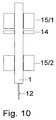
- FIG. 10 shows an embodiment in which the linear motor 15 is divided into an upper part 15/1 and a lower part 15/2, whereby can be accomplished by centering the needle bar 1.
Landscapes
- Engineering & Computer Science (AREA)
- Physics & Mathematics (AREA)
- Electromagnetism (AREA)
- Textile Engineering (AREA)
- Chemical & Material Sciences (AREA)
- Combustion & Propulsion (AREA)
- Power Engineering (AREA)
- Mechanical Engineering (AREA)
- Sewing Machines And Sewing (AREA)
- Linear Motors (AREA)
Abstract
Description
- Fig. 1
- einen Längsschnitt durch eine erste Ausführungsform eines elektromagnetischen Linarantriebes,
- Fig. 2
- einen Querschnitt durch die Ausführungsform nach Fig. 1,
- Fig. 3
- einen Längsschnitt durch eine zweite, runde Ausführungsform eines Linearantriebes,
- Fig. 4
- einen Längsschnitt mit einem Spulenkörper,
- Fig. 5
- einen Querschnitt durch die Ausführungsform nach Fig. 4,
- Fig. 6
- einen 12-spuligen Linearantrieb,
- Fig. 7 bis 9
- verschiedene Ausführungsformen einer Magnetlagerung für die Nadelstange, und
- Fig. 10
- eine Ausführungsform, bei welcher der Linearmotor in zwei voneinander beabstandete Abschnitte aufgeteilt ist.

Claims (9)
- Antrieb für eine Nähmaschine, insbesondere eine Industrienähmaschine, mit einer elektromagnetisch direkt angetriebenen Nadelstange, wobei gesondert hiervon mittels eines eigenen Motors eine untere Welle angetrieben wird, von welcher wenigstens der Antrieb von Greifer und Transporteur abgeleitet wird, dadurch gekennzeichnet, daß an der Nadelstange (1) eine Mehrzahl von Magneten (2) befestigt ist, wobei aufeinanderfolgende Magneten (2) jeweils entgegengesetzte Magnetisierungen aufweisen, daß durch einen Luftspalt (3) von diesen Magneten (2) getrennt ortsfest eine Mehrzahl von Spulen (Windungen 9) angeordnet ist, deren Polabstand zum Abstand der Magneten (2) korrespondiert, und daß die Bestromung der Spulen (Windungen 9) derart gesteuert wird, daß die Nadelstange (1) eine lineare Auf- und Abbewegung entsprechend einem vorgebbaren Geschwindigkeits- bzw. Beschleunigungsprofil ausführt.
- Antrieb nach Anspruch 1, dadurch gekennzeichnet, daß die Periodendauer der Nadelstangenbewegung mit der Periodendauer des Antriebs des Greifers übereinstimmt und im Fadenfangbereich eine Winkelsynchronisation bewerkstelligt wird.
- Antrieb nach Anspruch 1, dadurch gekennzeichnet, daß die Spulen (Windungen 9) für den Nadelstangenantrieb derart angesteuert werden, daß die Nadelstange (1) im Zeitpunkt des Ein- bzw. Durchstechens durch den Stoff eine erhöhte kinetische Energie aufweist.
- Antrieb nach Anspruch 1, dadurch gekennzeichnet, daß die Unterwelle durch einen Drehfeldmotor angetrieben wird.
- Antrieb nach Anspruch 4, dadurch gekennzeichnet, daß ein Steuerprozessor den Nadelstangenantrieb und den Drehfeldmotor anfangssynchron und phasenstarr ansteuert.
- Antrieb nach Anspruch 1, dadurch gekennzeichnet, daß an den Umkehrpunkten der Nadelstange (1) bei deren Abbremsen die Abbremsenergie in einem Zwischenkreis, insbesondere in einen Zwischenkreiskondensator zurückgespeist und beim erneuten Beschleunigen wider in kinetische Energie umgewandelt wird.
- Antrieb nach Anspruch 1, dadurch gekennzeichnet, daß die Nadelstange (1) wenigstens teilweise über eine Magnetlagerung (13) gelagert ist.
- Antrieb nach Anspruch 7, dadurch gekennzeichnet, daß ein oberes Magnetlager der Nadelstange (1) durch den Linearantrieb (15) selbst gebildet ist und eine mechanische Haltebremse (14) vorgesehen ist, die an der Nadelstange (1) bei ausgeschaltetem Netz angreift und beim Einschalten des Netzes außer Eingriff gebracht wird.
- Antrieb nach Anspruch 7, dadurch gekennzeichnet, daß der Linearmotor (15) in einen oberen Teil 15/1 und einen unteren Teil 15/2 aufgeteilt ist.
Applications Claiming Priority (2)
| Application Number | Priority Date | Filing Date | Title |
|---|---|---|---|
| DE19827846 | 1998-06-23 | ||
| DE1998127846 DE19827846C2 (de) | 1998-06-23 | 1998-06-23 | Antrieb für eine Nähmaschine, insbesondere eine Industrienähmaschine |
Publications (3)
| Publication Number | Publication Date |
|---|---|
| EP0967316A2 true EP0967316A2 (de) | 1999-12-29 |
| EP0967316A3 EP0967316A3 (de) | 2000-07-19 |
| EP0967316B1 EP0967316B1 (de) | 2003-07-30 |
Family
ID=7871693
Family Applications (1)
| Application Number | Title | Priority Date | Filing Date |
|---|---|---|---|
| EP19990109421 Expired - Lifetime EP0967316B1 (de) | 1998-06-23 | 1999-05-11 | Antrieb für eine Nähmaschine, insbesondere eine Industrienähmaschine |
Country Status (2)
| Country | Link |
|---|---|
| EP (1) | EP0967316B1 (de) |
| DE (1) | DE19827846C2 (de) |
Cited By (8)
| Publication number | Priority date | Publication date | Assignee | Title |
|---|---|---|---|---|
| DE10025822A1 (de) * | 2000-05-25 | 2001-12-06 | Quick Rotan Elektromotoren | Vorrichtung zum Transportieren von Nähgut |
| WO2002098777A1 (fr) * | 2001-06-07 | 2002-12-12 | Rieter Icbt | Dispositif de va et vient pour le renvidage d'un fil sous la forme d'une bobine |
| FR2825692A1 (fr) * | 2001-06-07 | 2002-12-13 | Rieter Icbt | Mecanisme de va et vient pour le bobinage de fils a grande vitesse |
| WO2002103721A1 (en) * | 2001-06-19 | 2002-12-27 | Ahmad Razzaghi | An electromagnetic power device |
| WO2008037570A1 (de) * | 2006-09-26 | 2008-04-03 | Schaeffler Kg | Stickkopf |
| WO2020144352A1 (de) * | 2019-01-13 | 2020-07-16 | Long-Time-Liner Conture Make-Up Gmbh | Linearantrieb für pigmentiergeräte |
| CN113871191A (zh) * | 2021-10-21 | 2021-12-31 | 东莞市技立自动化科技有限公司 | 自动分线机构 |
| RU2772344C1 (ru) * | 2019-01-13 | 2022-05-19 | Лонг-Тайм-Лайнер Контур Мэйк-Ап Гмбх | Линейный привод для устройств пигментирования |
Families Citing this family (8)
| Publication number | Priority date | Publication date | Assignee | Title |
|---|---|---|---|---|
| DE10202352C1 (de) * | 2002-01-23 | 2003-07-10 | Miele & Cie | Waschmaschine mit Antriebssystem |
| DE10211528A1 (de) | 2002-03-15 | 2003-09-25 | Ksl Keilmann Sondermaschb Gmbh | Nähmaschine |
| DE102005029876B4 (de) * | 2005-06-27 | 2009-03-19 | Kastriot Merlaku | Nähmaschine oder Antrieb-System für Nähmaschinen |
| DE102006042332A1 (de) * | 2006-09-08 | 2008-03-27 | Dürkopp Adler AG | Nähmaschine zum Vernähen zweier Nähgutteile unter Einarbeitung von Mehrweite |
| DE102008053750A1 (de) * | 2008-10-29 | 2010-05-06 | Dürkopp Adler AG | Nähmaschine |
| JP6373022B2 (ja) * | 2014-03-12 | 2018-08-15 | 独立行政法人国立高等専門学校機構 | リニアモータ |
| DE102015007998B4 (de) * | 2015-06-24 | 2024-09-05 | Capex lnvest GmbH | Vorrichtung und Verfahren zum Durchdringen eines flächenhaften, biegeschlaffen Körpers |
| CN105386254A (zh) * | 2015-12-14 | 2016-03-09 | 叶军忠 | 一种缝盘机上用的精密直线运动模组 |
Family Cites Families (11)
| Publication number | Priority date | Publication date | Assignee | Title |
|---|---|---|---|---|
| US2232692A (en) * | 1940-01-09 | 1941-02-25 | Singer Mfg Co | Electromagnetic sewing machine |
| US2584013A (en) * | 1948-05-13 | 1952-01-29 | Hagquist Arne | Sewing machine |
| GB663059A (en) * | 1949-05-09 | 1951-12-12 | Arne Hagquist | Improvements in and relating to sewing machines |
| BE494263A (de) * | 1949-03-02 | |||
| SE220043C1 (de) * | 1963-07-01 | 1968-04-09 | ||
| US3875489A (en) * | 1971-02-10 | 1975-04-01 | Brimer Joe W Von | Linear self synchronous electromagnetic drive system for a sewing machine |
| GB1429822A (en) * | 1971-02-10 | 1976-03-31 | Coxon P | Sewing machines |
| JPS61109591A (ja) * | 1984-11-02 | 1986-05-28 | プリンスミシン株式会社 | ミシン |
| US5189971A (en) * | 1990-10-29 | 1993-03-02 | Frankel Samuel R | Electronic sewing machine |
| WO1997015708A1 (en) * | 1995-10-24 | 1997-05-01 | Jimtex Developments Limited | Needle reciprocation |
| JPH10146487A (ja) * | 1996-11-19 | 1998-06-02 | Brother Ind Ltd | 主軸釜分離駆動型ミシン |
-
1998
- 1998-06-23 DE DE1998127846 patent/DE19827846C2/de not_active Expired - Fee Related
-
1999
- 1999-05-11 EP EP19990109421 patent/EP0967316B1/de not_active Expired - Lifetime
Cited By (14)
| Publication number | Priority date | Publication date | Assignee | Title |
|---|---|---|---|---|
| DE10025822A1 (de) * | 2000-05-25 | 2001-12-06 | Quick Rotan Elektromotoren | Vorrichtung zum Transportieren von Nähgut |
| DE10025822C2 (de) * | 2000-05-25 | 2002-05-08 | Quick Rotan Elektromotoren | Vorrichtung zum Transportieren von Nähgut |
| DE10025822C5 (de) * | 2000-05-25 | 2008-09-18 | Quick Rotan Elektromotoren Gmbh | Vorrichtung zum Transportieren von Nähgut |
| WO2002098777A1 (fr) * | 2001-06-07 | 2002-12-12 | Rieter Icbt | Dispositif de va et vient pour le renvidage d'un fil sous la forme d'une bobine |
| FR2825692A1 (fr) * | 2001-06-07 | 2002-12-13 | Rieter Icbt | Mecanisme de va et vient pour le bobinage de fils a grande vitesse |
| US6856050B2 (en) | 2001-06-07 | 2005-02-15 | Rieter Textile Machinery France | Reciprocating device for winding a yarn in the form of a package |
| US7064461B2 (en) | 2001-06-19 | 2006-06-20 | Ahmad Razzaghi | Electromagnetic power device |
| WO2002103721A1 (en) * | 2001-06-19 | 2002-12-27 | Ahmad Razzaghi | An electromagnetic power device |
| WO2008037570A1 (de) * | 2006-09-26 | 2008-04-03 | Schaeffler Kg | Stickkopf |
| WO2020144352A1 (de) * | 2019-01-13 | 2020-07-16 | Long-Time-Liner Conture Make-Up Gmbh | Linearantrieb für pigmentiergeräte |
| RU2772344C1 (ru) * | 2019-01-13 | 2022-05-19 | Лонг-Тайм-Лайнер Контур Мэйк-Ап Гмбх | Линейный привод для устройств пигментирования |
| US12090296B2 (en) | 2019-01-13 | 2024-09-17 | Long-Time-Liner Conture Make-Up Gmbh | Linear drive for pigmentation devices |
| CN113871191A (zh) * | 2021-10-21 | 2021-12-31 | 东莞市技立自动化科技有限公司 | 自动分线机构 |
| CN113871191B (zh) * | 2021-10-21 | 2024-01-30 | 东莞市技立自动化科技有限公司 | 自动分线机构 |
Also Published As
| Publication number | Publication date |
|---|---|
| DE19827846C2 (de) | 2001-05-31 |
| DE19827846A1 (de) | 1999-12-30 |
| EP0967316B1 (de) | 2003-07-30 |
| EP0967316A3 (de) | 2000-07-19 |
Similar Documents
| Publication | Publication Date | Title |
|---|---|---|
| EP0967316B1 (de) | Antrieb für eine Nähmaschine, insbesondere eine Industrienähmaschine | |
| DE3705089C2 (de) | ||
| EP0159005B2 (de) | Elektrisch gesteuerter Elektromotor | |
| EP1858142A1 (de) | Linearmotor | |
| DE60205618T2 (de) | Fadenverlegung für eine vorrichtung zum aufwickeln eines fadens auf eine spule | |
| EP0363405B1 (de) | Mehrphasige, permanentmagneterregte elektrische maschine synchroner bauart | |
| DE1941097A1 (de) | Magnetische Turbine | |
| DE2804787A1 (de) | Kollektorloser gleichstrommotor | |
| DE2310386A1 (de) | Elektromagnetisches antriebssystem, sowie naehmaschine mit einem solchen | |
| DE2451718B2 (de) | Elektrischer Antrieb mit radial und axial verschiebbarem Läufer | |
| EP3238329B1 (de) | Verfahren zum betrieb einer reluktanzmaschine sowie reluktanzmaschine | |
| EP0400455A1 (de) | Synchronmotor sowie Verfahren zum Betreiben dieses Synchronmotors | |
| DE2029462C3 (de) | Linearmaschine mit Repulsionswirkung für einphasigen Wechselstrom | |
| DE69821041T2 (de) | Modularer elektrischer Motor | |
| EP1402546A1 (de) | Elektrodynamischer linearantrieb | |
| DE69622515T2 (de) | Gerät und Verfahren zur Verringerung der Eisenverluste in einer geschalteten Reluktanzmaschine | |
| DE310510C (de) | ||
| DE2706691C3 (de) | Motor | |
| DE102019004428A1 (de) | Elektronisch kommutierter Elektromotor | |
| DE19504641A1 (de) | Aktuator für den Antrieb von Strickmaschinennadeln | |
| DE2229230C3 (de) | Nähmaschinenantrieb | |
| DE260102C (de) | ||
| DE2923575C2 (de) | Elektromagnetische Antriebseinrichtung zum Betätigen der Nähwerkzeuge einer Nähmaschine | |
| DE1788126A1 (de) | Elektrischer Schrittschaltmotor | |
| DE729008C (de) | Verfahren zur Trennung von nichtmagnetisierbaren Metallkoerpern auf magnetischem Wege |
Legal Events
| Date | Code | Title | Description |
|---|---|---|---|
| PUAI | Public reference made under article 153(3) epc to a published international application that has entered the european phase |
Free format text: ORIGINAL CODE: 0009012 |
|
| AK | Designated contracting states |
Kind code of ref document: A2 Designated state(s): FR GB IT |
|
| AX | Request for extension of the european patent |
Free format text: AL;LT;LV;MK;RO;SI |
|
| PUAL | Search report despatched |
Free format text: ORIGINAL CODE: 0009013 |
|
| AK | Designated contracting states |
Kind code of ref document: A3 Designated state(s): AT BE CH CY DE DK ES FI FR GB GR IE IT LI LU MC NL PT SE |
|
| AX | Request for extension of the european patent |
Free format text: AL;LT;LV;MK;RO;SI |
|
| 17P | Request for examination filed |
Effective date: 20001212 |
|
| AKX | Designation fees paid |
Free format text: FR GB IT |
|
| GRAG | Despatch of communication of intention to grant |
Free format text: ORIGINAL CODE: EPIDOS AGRA |
|
| GRAG | Despatch of communication of intention to grant |
Free format text: ORIGINAL CODE: EPIDOS AGRA |
|
| GRAH | Despatch of communication of intention to grant a patent |
Free format text: ORIGINAL CODE: EPIDOS IGRA |
|
| 17Q | First examination report despatched |
Effective date: 20020524 |
|
| REG | Reference to a national code |
Ref country code: DE Ref legal event code: 8566 |
|
| GRAH | Despatch of communication of intention to grant a patent |
Free format text: ORIGINAL CODE: EPIDOS IGRA |
|
| GRAA | (expected) grant |
Free format text: ORIGINAL CODE: 0009210 |
|
| AK | Designated contracting states |
Designated state(s): FR GB IT |
|
| REG | Reference to a national code |
Ref country code: GB Ref legal event code: FG4D Free format text: NOT ENGLISH |
|
| GBT | Gb: translation of ep patent filed (gb section 77(6)(a)/1977) |
Effective date: 20031204 |
|
| ET | Fr: translation filed | ||
| PLBE | No opposition filed within time limit |
Free format text: ORIGINAL CODE: 0009261 |
|
| STAA | Information on the status of an ep patent application or granted ep patent |
Free format text: STATUS: NO OPPOSITION FILED WITHIN TIME LIMIT |
|
| 26N | No opposition filed |
Effective date: 20040504 |
|
| PGFP | Annual fee paid to national office [announced via postgrant information from national office to epo] |
Ref country code: FR Payment date: 20120608 Year of fee payment: 14 Ref country code: GB Payment date: 20120522 Year of fee payment: 14 |
|
| PGFP | Annual fee paid to national office [announced via postgrant information from national office to epo] |
Ref country code: IT Payment date: 20120521 Year of fee payment: 14 |
|
| GBPC | Gb: european patent ceased through non-payment of renewal fee |
Effective date: 20130511 |
|
| PG25 | Lapsed in a contracting state [announced via postgrant information from national office to epo] |
Ref country code: IT Free format text: LAPSE BECAUSE OF NON-PAYMENT OF DUE FEES Effective date: 20130511 |
|
| REG | Reference to a national code |
Ref country code: FR Ref legal event code: ST Effective date: 20140131 |
|
| PG25 | Lapsed in a contracting state [announced via postgrant information from national office to epo] |
Ref country code: GB Free format text: LAPSE BECAUSE OF NON-PAYMENT OF DUE FEES Effective date: 20130511 |
|
| PG25 | Lapsed in a contracting state [announced via postgrant information from national office to epo] |
Ref country code: FR Free format text: LAPSE BECAUSE OF NON-PAYMENT OF DUE FEES Effective date: 20130531 |