EP0966984A2 - Konnektorelement - Google Patents
Konnektorelement Download PDFInfo
- Publication number
- EP0966984A2 EP0966984A2 EP99111745A EP99111745A EP0966984A2 EP 0966984 A2 EP0966984 A2 EP 0966984A2 EP 99111745 A EP99111745 A EP 99111745A EP 99111745 A EP99111745 A EP 99111745A EP 0966984 A2 EP0966984 A2 EP 0966984A2
- Authority
- EP
- European Patent Office
- Prior art keywords
- connector element
- pipe socket
- connector
- shut
- piercing body
- Prior art date
- Legal status (The legal status is an assumption and is not a legal conclusion. Google has not performed a legal analysis and makes no representation as to the accuracy of the status listed.)
- Granted
Links
Images


Classifications
-
- A—HUMAN NECESSITIES
- A61—MEDICAL OR VETERINARY SCIENCE; HYGIENE
- A61M—DEVICES FOR INTRODUCING MEDIA INTO, OR ONTO, THE BODY; DEVICES FOR TRANSDUCING BODY MEDIA OR FOR TAKING MEDIA FROM THE BODY; DEVICES FOR PRODUCING OR ENDING SLEEP OR STUPOR
- A61M39/00—Tubes, tube connectors, tube couplings, valves, access sites or the like, specially adapted for medical use
- A61M39/10—Tube connectors; Tube couplings
- A61M39/14—Tube connectors; Tube couplings for connecting tubes having sealed ends
-
- A—HUMAN NECESSITIES
- A61—MEDICAL OR VETERINARY SCIENCE; HYGIENE
- A61M—DEVICES FOR INTRODUCING MEDIA INTO, OR ONTO, THE BODY; DEVICES FOR TRANSDUCING BODY MEDIA OR FOR TAKING MEDIA FROM THE BODY; DEVICES FOR PRODUCING OR ENDING SLEEP OR STUPOR
- A61M39/00—Tubes, tube connectors, tube couplings, valves, access sites or the like, specially adapted for medical use
- A61M39/10—Tube connectors; Tube couplings
- A61M2039/1027—Quick-acting type connectors
-
- A—HUMAN NECESSITIES
- A61—MEDICAL OR VETERINARY SCIENCE; HYGIENE
- A61M—DEVICES FOR INTRODUCING MEDIA INTO, OR ONTO, THE BODY; DEVICES FOR TRANSDUCING BODY MEDIA OR FOR TAKING MEDIA FROM THE BODY; DEVICES FOR PRODUCING OR ENDING SLEEP OR STUPOR
- A61M39/00—Tubes, tube connectors, tube couplings, valves, access sites or the like, specially adapted for medical use
- A61M39/10—Tube connectors; Tube couplings
- A61M2039/1061—Break-apart tubing connectors or couplings
-
- Y—GENERAL TAGGING OF NEW TECHNOLOGICAL DEVELOPMENTS; GENERAL TAGGING OF CROSS-SECTIONAL TECHNOLOGIES SPANNING OVER SEVERAL SECTIONS OF THE IPC; TECHNICAL SUBJECTS COVERED BY FORMER USPC CROSS-REFERENCE ART COLLECTIONS [XRACs] AND DIGESTS
- Y10—TECHNICAL SUBJECTS COVERED BY FORMER USPC
- Y10S—TECHNICAL SUBJECTS COVERED BY FORMER USPC CROSS-REFERENCE ART COLLECTIONS [XRACs] AND DIGESTS
- Y10S604/00—Surgery
- Y10S604/905—Aseptic connectors or couplings, e.g. frangible, piercable
Definitions
- the present invention relates to a connector element, in particular for connection of tubes, cannulas and catheters with an area for guiding a flowing medium, with a shut-off element through which the area to Guide of the medium is closable and with an area for receiving a piercing body, which is designed such that the piercing body is relative is movable to the shut-off element and the shut-off element during connection is opened by the piercing body.
- connectors An important area of use for connectors is the connection of a container via a hose line with medical equipment, for example with a dialyzer, or the connection of two hose ends to the Purposes of providing extension leads. To always be sterile and ensure a tight connection and thus a risk to patients exclude high demands on the execution and quality of the Connectors as well as the type of connection of the connectors, causing contamination not only before, but also during and after Connection should be prevented.
- WO 82/02528 describes a connector system made up of two connector elements disclosed, in which the connector elements prior to the connection by means of thermoplastic membranes are closed.
- the connector elements are on their end facing away from the thermoplastic membrane in each case with a Connected hose, which in turn, for example, with a container for receiving of dialysis fluids or in connection with a dialysis machine.
- the connector elements point to the opening in the hoses Hose membranes on a tapered end.
- the opening of the Hose membranes by means of the pointed ends of the connector elements, the Movement of the pointed ends relative to the hose membranes through a bellows executed area of the hose is made possible.
- the connector provides a complex system made up of different membranes and connector elements on what the manufacture of the connectors is correspondingly complex and expensive designed.
- WO 94/08173 describes a connector system with two connector elements, which are each closed by membranes. After merging the A displaceable dome is guided through the membranes in a membrane the connector elements is movably arranged. In the unconnected state the dome is recorded in a room by one of the membranes is limited. Accordingly, it is necessary to manufacture the membrane after inserting the mandrel to fix later on the connector element, which the Manufacturing process of the connector designed relatively expensive.
- a generic connector element which has a puncture body which is relative to one as an elastomeric membrane executed shut-off element is movable and opens this at the connection.
- the piercing body has a male Luer cone on its opening side which cooperates with a corresponding female cone during the connection.
- the elastomeric membrane extends over the area for guiding one flowing medium and closes it in the disconnected state.
- the membrane lies against a step of the connector element and is there pressed by means of a fitting. It is such a connector element disadvantage that this is made up of several different materials and that the membrane is inserted later and fixed liquid-tight got to.
- This task is based on a generic connector element solved in that the shut-off element as a monomaterial component of the connector element is executed.
- This makes it relatively easy to manufacture the connector elements allows because the shut-off element is an integral part of the connector element and a subsequent positioning and Fixation is not necessary.
- Subsequent application of membranes is thus not mandatory. This not only simplifies the manufacture of the connectors, but because of the possibility of the connector elements and shut-off elements Manufacturing in one step also becomes a particularly dense arrangement reached. Subsequent welding, for example of film membranes or the subsequent welding or arrangement of membrane-populated Individual components and a correspondingly complex inspection can accordingly eliminated.
- the shut-off element is designed as an injection molded membrane.
- the injection molding membrane can same operation can be made with the connector element, creating a subsequent application of shut-off elements of any shape becomes unnecessary.
- the area to guide the medium includes
- the area for guiding the medium is one Pipe socket includes.
- the Connector element has a housing and the pipe socket in the housing is recorded.
- the pipe socket through the shut-off element For example, a membrane, be closed, which results in tightness and sterility of the connected hoses or containers is ensured.
- the piercing body is arranged in the pipe socket.
- the arrangement is such that a Cutting or opening the shut-off element through the piercing body he follows.
- the housing can serve the pipe socket as well as the shut-off element against unwanted touching and introduction of contaminants protect.
- the housing diameter can be designed such that a accidental contact with the pipe socket or the areas after the connection with liquid or gas, is not possible.
- the locking device can run around the outer circumference of the piercing body Groove and a projection extending on the inner circumference of the pipe socket include. During or after the manufacture or before using the connector the piercing body can be inserted into the pipe socket accordingly and are held in the desired position by the lock.
- the piercing body is designed such that this through a pipe socket a further connector element to be connected to the connector element is detachable from the lock. This ensures that only during the Connection of the piercing body is released from its locking and by means of a Pipe socket is moved such that the severing or opening of the Shut-off element takes place.
- the lock is advantageously designed such that the shut-off element of one of the connector elements is first cut before the corresponding pipe socket releases the puncture body from the detent and then the second shut-off element or the second membrane is severed.
- the piercing body can be released from the locking device in that this has a projection arranged on the outer circumference, which with the Pipe socket of a further connector element to be connected to the connector element is connectable.
- the housing and the Pipe socket of a further connector element to be connected to the connector element are at least partially recordable. This is done by an appropriate Design of the inner or outer diameter of the adjacent Components reached.
- the pipe socket is beveled in its end region is. This will push one of the pipe sockets into this receiving pipe socket facilitates, advantageously expanding the receiving Pipe socket takes place, which is a particularly tight connection between the two Ensures pipe socket.
- the connection and, if necessary, the disconnection can be done by machine or by hand. It is advantageous if the deconnection is connected with a higher power requirement due to the design than the connector. If necessary, constructive elements, for example injection molding, integrate that make disconnection impossible.
- the piercing body is essentially cylindrical Form and pointed at its ends. This makes it proportional simple and low-force opening of the shut-off elements or Enables membranes. It is also possible to notch the puncture body or perforated or in a star profile shape.
- the Connector element and the piercing body are designed as injection molded parts.
- the production can be carried out inexpensively in multiple injection molds. This enables the parts to be easily manufactured in many different ways Embodiments.
- this Housing and the pipe socket of the connector element cylindrical outer and Inner surfaces on this has the advantage that neither in the manufacture nor in the Application of the connector system rotary positions are required. Much more can the connection by simply inserting one of the connector element into the other connector element. With an appropriate design the housing of the connector elements can be achieved that a special good protection against contact results. Typical values for the inside diameter of the housing are 8.6 mm for the female connector and 7.4 mm for the male connector, which is good protection against accidental contact also against the penetration thinner Guaranteed fingertips.
- the end of the pipe socket can be on the inside or outside surface have circumferential projection, by means of which a sealing connection with an inserted or receiving pipe socket of another connector element can be produced.
- This also has the advantage that a seal relative to the ambient atmosphere before it pierces the shut-off elements or the membranes comes. Endanger accordingly also high and low pressures between the liquid and gas-filled zones of the connector elements relative to the environment and pressure differences between the connector elements, depending on the dimensioning of the arrangement up to several Bar amount, not sterility and tightness before, during and after of the connection, since there is always a tight connection between those to be connected Connector elements is produced, and only in the next step the sealing membranes be pierced.
- the shut-off element and the area for receiving the piercing body are arranged in this way are that the piercing body from the connector side of the connector element can be introduced.
- the term connection side is the side of the To understand connector element on which a connector element to be connected should be introduced or plugged on.
- the connector element according to the invention is an integral part for example an injection molded component, i.e. if the connector element is produced together with this component.
- a component can e.g. be a cassette-like component for fluid management and / or treatment.
- the shut-off element or the membrane is arranged such that the Piercing body can be inserted from the outside or from the connection side.
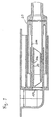
- the connector element 10 has the housing 108 in which the pipe socket 106 extends. At the end extending to the left in FIG. 1 there is an opening in housing 108, for example for receiving a Hose end. This opening and the one delimited by the pipe socket 106 Area define area 102 for guiding a medium flowing through, for example a liquid or a gas.
- the area 102 is indicated by the as Shutter element serving membrane 104 sealed.
- the puncture body 30 is received, which by means of Lock 40 is held in a desired position in the pipe socket 106.
- the locking device 40 consists of a extending on the inner circumference of the pipe socket 106, the in a corresponding circumferential groove on the outer circumference of the piercing body 30 engages.
- the puncture body has a circumferential on its outer circumference Projection 302 on.
- the connector element 20 has a housing 208 in which the pipe socket 206 is recorded. In the part of the housing 208 shown on the right in FIG. 1 a hose or any work equipment can be connected. Of the Pipe socket 206 and the adjoining area for receiving a Hose or work equipment delimit the area 202 for guiding one flowing medium. This is by a serving as a shut-off element Membrane 204 is sealed in the area of the pipe socket 206. Thus it results there is also a tight and reliable shut-off for this connector element 20 against the undesired penetration of contaminants.
- the membranes 104, 204 are hermetically sealed and free of dead spaces as injection-molded membranes and mono material, i.e. they are produced simultaneously with the Manufacture of the connector elements 10, 20. This results in a proportionate easy manufacture of the connectors according to the invention and on the other a particularly high reliability of the membranes. In particular, is an ex post Welding of film membranes or other shut-off elements and a corresponding review is unnecessary. Rather, the invention Injection molded membranes in the start phase of series production 100% and later in the sampling process by simple pressure maintenance tests for integrity being checked. This test and other property tests are carried out advantageous already at the supplier of the injection molded parts or in the quality control laboratories.
- a check on the main assembly line or a subsequent check joined membranes becomes superfluous. In addition, the separation does not apply by committee due to leakage on the main assembly line.
- a typical one Thickness of the injection molded membranes forming the shut-off elements 104, 204 is 0.2 mm.
- the connector element 10 is according to the present embodiment as integral component of a cassette-like component for fluid management and / or treatment and is produced together with this.
- the wall 12 of the cassette-like component is located directly above the housing 108. Relative to any directions of the output of the connector element 10 to the cassette wall 12, the area 102 for receiving the Piercing body 30 and the shut-off element 104 arranged such that the Puncture body from the connection side of the connector shown on the right in FIG. 1 Connector element 10 is insertable. This makes it possible to change the direction of connection in any orientation relative to the cassette-like component or to execute its wall 12. Because of such an embodiment, the Puncture body easily introduced into the corresponding receiving area become.
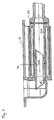
- the connector elements 10, 20 are based on that shown in FIG. 1 Assembled position, the housing 208 and is first inserted of the pipe socket 206 of the connector element 20 in the housing 108 and the Pipe socket 106 of the connector element 10 to that designed as a membrane Shut-off element 204 bears against the right end region of the piercing body 30, such as this is shown in Fig. 2.
- the housing 208 in the housing 108 and the pipe socket 206 inserted into the pipe socket 106.
- the Pipe sockets 106, 206 are in their end regions in order to facilitate this introduction beveled.
- the housing 108 and the pipe socket 106 in the corresponding parts of the connector element 20 are included.
- the piercing body 30 is not arranged in the first 10, but in the connector element 20.
- the state shown in FIG. 3 results.
- the shut-off element of the connector element 20 severed.
- the end region of the pipe socket 206 lies on the projection 302 of the piercing body 30.
- one of the shut-off elements designed as membranes, while the other Shut-off element 104 is still closed. This is due to the fact that the Piercing body 30 up to the state shown in Fig. 3 in the locked Position is held.
- a further displacement or merging of the connector elements 10, 20 finally leads to the arrangement shown in FIG. 4.
- the contact of the front End of the pipe socket 206 of the second connector element 20 with the projection 302 of the puncture body 30 leads to the puncture body 30 executing the lock 40 is released and with its pointed end shown on the left cut off as a diaphragm shut-off element. With that lies a reliable sealed and sterile passage between the connector elements 10, 20 before.
- the inside diameter of the housings 108, 208 can advantageously be selected in such a way that that effective protection against contact results from the fact that an intrusion with Fingers becomes impossible.
- the receiving connector element advantageously has one Inner diameter of 8.6 mm and the connector element to be inserted Inner diameter of 7.4 mm. Typical values for the outside diameter and the insertion depth of the connector element to be inserted is 8.4 mm or at least 22 mm.
- the connector element according to the invention ensures tightness before and after the connection. It plays over it for the safe connection process It does not matter whether the connectors are filled with liquid or gas. Subsequent Connections during use are therefore possible. The flow direction plays here not matter.
Abstract
Description
- Fig. 1:
- Eine Schnittdarstellung durch zwei erfindungsgemäße Konnektorelemente in einer Grundstellung vor der Konnektion,
- Fig. 2:
- die Konnektorelemente gemäß Fig. 1 nach dem Einführen des rechts dargestellten Konnektorelementes bis zum Anliegen der Membran an dem Durchstoßkörper,
- Fig. 3:
- die Konnektorelemente gemäß Fig. 1 nach dem Öffnen der Membran des rechts dargestellten Konnektorelementes und
- Fig. 4:
- die Konnektorelemente gemäß Fig. 1 nach dem Durchtrennen beider Membranen durch den Durchstoßkörper.
Claims (18)
- Konnektorelement (10, 20) insbesondere zum Verbinden von Schläuchen, Kanülen und Kathetern mit einem Bereich (102, 202) zur Führung eines durchströmenden Mediums, mit einem Absperrelement (104, 204), durch das der Bereich (102, 202) zur Führung des Mediums verschließbar ist sowie mit einem Bereich (102, 202) zur Aufnahme eines Durchstoßkörpers (30), der derart ausgestattet ist, daß der Durchstoßkörper (30) relativ zu dem Absperrelement (104, 204) bewegbar ist und das Absperrelement (104, 204) bei der Konnektion durch den Durchstoßkörper (30) geöffnet wird,
dadurch gekennzeichnet,daß das Absperrelement (104, 204) als monomaterialer Bestandteil des Konnektorelementes (10, 20) ausgeführt ist. - Konnektorelement (10, 20) nach Anspruch 1, dadurch gekennzeichnet, daß das Absperrelement (104, 204) als Spritzgußmembran ausgeführt ist.
- Konnektorelement (10, 20) nach Anspruch 1 oder 2, dadurch gekennzeichnet, daß der Bereich (102, 202) zur Führung des Mediums den Bereich (102, 202) zur Aufnahme des Durchstoßkörpers (30) umfaßt.
- Konnektorelement (10, 20) nach einem oder mehreren der Ansprüche 1 bis 3, dadurch gekennzeichnet, daß der Bereich (102, 202) zur Führung des Mediums einen Rohrstutzen (106, 206) umfaßt.
- Konnektorelement (10, 20) nach Anspruch 4, dadurch gekennzeichnet, daß das Konnektorelement (10, 20) ein Gehäuse (108, 208) aufweist und der Rohrstutzen (106, 206) in dem Gehäuse (108, 208) aufgenommen ist.
- Konnektorelement (10, 20) nach Anspruch 4 oder 5, dadurch gekennzeichnet, daß ein Durchstoßkörper (30) vorgesehen ist, der in den Rohrstutzen (106) einführbar und dort mittels einer Arretierung (40) fixierbar ist.
- Konnektorelement (10, 20) nach Anspruch 6, dadurch gekennzeichnet, daß die Arretierung (40) eine am Außenumfang des Durchstoßkörpers (30) umlaufende Nut und einen sich am Innenumfang des Rohrstutzens (106) erstreckenden Vorsprung umfaßt.
- Konnektorelement (10, 20) nach Anspruch 6 oder 7, dadurch gekennzeichnet, daß der Durchstoßkörper (30) derart ausgeführt ist, daß dieser durch einen Rohrstutzen (206) eines mit dem Konnektorelement (10) zu verbindenden weiteren Konnektorelementes (20) aus der Arretierung (40) lösbar ist.
- Konnektorelement (10, 20) nach Anspruch 8, dadurch gekennzeichnet, daß der Durchstoßkörper (30) einen am Außenumfang angeordneten Vorsprung (302) aufweist, der mit dem Rohrstutzen (206) eines mit dem Konnektorelement (10) zu verbindenden weiteren Konnektorelementes (20) verbindbar ist.
- Konnektorelement (10, 20) nach einem oder mehreren der Ansprüche 5 bis 9, dadurch gekennzeichnet, daß in dem Gehäuse (108) und dem Rohrstutzen (106) des Konnektorelementes (10) das Gehäuse (208) und der Rohrstutzen (206) eines mit dem Konnektorelement (10) zu verbindenden weiteren Konnektorelementes (20) wenigstens teilweise aufnehmbar sind.
- Konnektorelement (10, 20) nach einem oder mehreren der Ansprüche 4 bis 10, dadurch gekennzeichnet, daß der Rohrstutzen (106, 206) in seinem Endbereich abgeschrägt ist.
- Konnektorelement (10, 20) nach einem oder mehreren der Ansprüche 1 bis 11, dadurch gekennzeichnet, daß der Durchstoßkörper (30) eine im wesentlichen zylindrische Form aufweist und an seinen Enden spitz zuläuft.
- Konnektorelement (10, 20) nach einem oder mehreren der Ansprüche 1 bis 12, dadurch gekennzeichnet, daß das Konnektorelement (10, 20) sowie der Durchstoßkörper (30) als Spritzgußteile ausgeführt sind.
- Konnektorelement (10, 20) nach einem oder mehreren der Ansprüche 1 bis 13, dadurch gekennzeichnet, daß das Konnektorelement (10, 20) mit Absperrelement (104, 204) sowie der Durchstoßkörper (30) Polypropylen aufweisen.
- Konnektorelement (10, 20) nach einem oder mehreren der Ansprüche 4 bis 14, dadurch gekennzeichnet, daß das Gehäuse (108, 208) sowie der Rohrstutzen (106, 206) zylindrische Außen- und Innenflächen aufweisen.
- Konnektorelement (10, 20) nach einem oder mehreren der Ansprüche 4 bis 15, dadurch gekennzeichnet, daß die Innen- oder Außenflächen der Rohrstutzen (106, 206) abgeschrägt oder konisch ausgeführt sind.
- Konnektorelement (10, 20) nach einem oder mehreren der Ansprüche 4 bis 16, dadurch gekennzeichnet, daß die Rohrstutzen (106) in ihrem Endbereich auf der Innen- oder Außenfläche einen umlaufenden Vorsprung (107) aufweisen, mittels dessen eine dichtende Verbindung mit einem einzuführenden (206) oder aufnehmenden Rohrstutzen eines weiteren Konnektorelementes (10, 20) herstellbar ist.
- Konnektorelement (10, 20) nach einem oder mehreren der Ansprüche 1 bis 17, dadurch gekennzeichnet, daß das Absperrelement (104, 204) sowie der Bereich (102, 202) zur Aufnahme des Durchstoßkörpers (30) derart angeordnet sind, daß der Durchstoßkörper (30) von der Konnektionsseite des Konnektorelementes (10, 20) einführbar ist.
Applications Claiming Priority (2)
| Application Number | Priority Date | Filing Date | Title |
|---|---|---|---|
| DE19828650A DE19828650C2 (de) | 1998-06-26 | 1998-06-26 | Konnektorelement mit integriertem Absperrelement |
| DE19828650 | 1998-06-26 |
Publications (3)
| Publication Number | Publication Date |
|---|---|
| EP0966984A2 true EP0966984A2 (de) | 1999-12-29 |
| EP0966984A3 EP0966984A3 (de) | 2000-03-29 |
| EP0966984B1 EP0966984B1 (de) | 2005-08-17 |
Family
ID=7872187
Family Applications (1)
| Application Number | Title | Priority Date | Filing Date |
|---|---|---|---|
| EP99111745A Expired - Lifetime EP0966984B1 (de) | 1998-06-26 | 1999-06-17 | Konnektorelement |
Country Status (5)
| Country | Link |
|---|---|
| US (1) | US6234538B1 (de) |
| EP (1) | EP0966984B1 (de) |
| JP (1) | JP4287952B2 (de) |
| DE (2) | DE19828650C2 (de) |
| ES (1) | ES2248943T3 (de) |
Cited By (3)
| Publication number | Priority date | Publication date | Assignee | Title |
|---|---|---|---|---|
| EP2266631A1 (de) * | 2000-02-07 | 2010-12-29 | Ethicon, Inc. | Verfahren zur Abgabe und Dosierung von flüssigen Sterilisierungsmitteln |
| WO2011091895A1 (de) * | 2010-01-26 | 2011-08-04 | Raumedic Ag | Dicht-hülsenkörper |
| US9700665B2 (en) | 2011-07-29 | 2017-07-11 | Fresenius Medical Care Deutschland Gmbh | Contact protection apparatus for a medical fluid-conducting cassette and cassette |
Families Citing this family (31)
| Publication number | Priority date | Publication date | Assignee | Title |
|---|---|---|---|---|
| WO2000020792A1 (en) * | 1998-10-02 | 2000-04-13 | Aeroquip Corporation | Coupling assembly |
| US6471249B1 (en) * | 1998-10-08 | 2002-10-29 | John K. Lewis | Adjustable pipe connector |
| US7824343B2 (en) * | 1999-07-29 | 2010-11-02 | Fenwal, Inc. | Method and apparatus for blood sampling |
| US20030176813A1 (en) * | 1999-07-29 | 2003-09-18 | Jean-Marie Mathias | Biological fluid sampling apparatus |
| CA2373689A1 (en) * | 1999-07-29 | 2001-02-08 | Thomas W. Coneys | Sampling tube holder for blood sampling system |
| US7479131B2 (en) * | 1999-07-29 | 2009-01-20 | Fenwal, Inc. | Biological fluid sampling apparatus, assembly and method |
| SE0001278L (sv) * | 2000-04-06 | 2001-10-08 | Peter Unger Med P U Med Konsul | Sterilkoppling |
| DE10136262A1 (de) | 2001-07-25 | 2003-02-20 | Fresenius Medical Care De Gmbh | Verfahren und Vorrichtung sowie Konnektor und Konzentratbehältereinheit zur Zubereitung von Lösungen |
| ITMI20020819A1 (it) * | 2002-04-18 | 2003-10-20 | Gambro Lundia Ab | Elemento di connessione e dispositivo di collegamento per tubazioni ad uso medicale |
| US6902207B2 (en) * | 2002-05-01 | 2005-06-07 | Medtronic Minimed, Inc. | Self sealing disconnect device |
| US8215492B2 (en) | 2003-09-18 | 2012-07-10 | Pur Water Purification Products, Inc. | Water treatment devices and cartridges therefor |
| ITMO20040082A1 (it) * | 2004-04-13 | 2004-07-13 | Gambro Lundia Ab | Connettore per una linea di fluido di un circuito extacorporeo |
| ATE485075T1 (de) * | 2006-07-07 | 2010-11-15 | Caridianbct Inc | Verfahren zum verbinden thermoplastischer schläuche |
| WO2008070220A1 (en) * | 2006-12-05 | 2008-06-12 | Caridianbct, Inc. | Connector system for sterile connection |
| US7901376B2 (en) * | 2007-07-05 | 2011-03-08 | Baxter International Inc. | Dialysis cassette having multiple outlet valve |
| US8764702B2 (en) * | 2007-07-05 | 2014-07-01 | Baxter International Inc. | Dialysis system having dual patient line connection and prime |
| US7736328B2 (en) | 2007-07-05 | 2010-06-15 | Baxter International Inc. | Dialysis system having supply container autoconnection |
| US8157761B2 (en) | 2007-07-05 | 2012-04-17 | Baxter International Inc. | Peritoneal dialysis patient connection system |
| US8496609B2 (en) * | 2007-07-05 | 2013-07-30 | Baxter International Inc. | Fluid delivery system with spiked cassette |
| US7955295B2 (en) * | 2007-07-05 | 2011-06-07 | Baxter International Inc. | Fluid delivery system with autoconnect features |
| US8197087B2 (en) * | 2007-07-05 | 2012-06-12 | Baxter International Inc. | Peritoneal dialysis patient connection system using ultraviolet light emitting diodes |
| US20090143723A1 (en) * | 2007-11-29 | 2009-06-04 | Baxter International Inc. | Flow control device for peritoneal dialysis |
| US9044544B2 (en) * | 2008-11-21 | 2015-06-02 | Baxter International Inc. | Dialysis machine having auto-connection system with roller occluder |
| US20100211040A1 (en) * | 2009-02-19 | 2010-08-19 | Cetylite Industries, Inc. | Apparatus and method for dispensing fluid through a port connector |
| WO2014032991A1 (de) * | 2012-08-28 | 2014-03-06 | Fresenius Kabi Deutschland Gmbh | Konnektor zur herstellung einer fluidverbindung mit einem zweiten konnektor, konnektorsystem und verfahren zur herstellung einer fluidverbindung |
| JP6787903B2 (ja) | 2015-01-27 | 2020-11-18 | メディヴァンス インコーポレイテッドMedivance,Inc. | 熱療法用の改良された医療用パッド及びシステム |
| US20200408350A1 (en) | 2015-06-16 | 2020-12-31 | Juan Nepomuc Walterspiel | Tubing connector for decreased contamination |
| CA2986808A1 (en) * | 2015-06-16 | 2016-12-22 | Juan WALTERSPIEL | Tubing connector for decreased contamination |
| DE102017101730A1 (de) | 2017-01-30 | 2018-08-02 | Fresenius Medical Care Deutschland Gmbh | Neue Berührschutzvorrichtung für medizinische fluidführende Kassette und Kassette |
| US11559811B2 (en) * | 2017-02-10 | 2023-01-24 | Lonza Ltd. | Cell culture system and method |
| US20220288374A1 (en) * | 2021-03-11 | 2022-09-15 | Bellco S.R.L. | Connector system |
Citations (5)
| Publication number | Priority date | Publication date | Assignee | Title |
|---|---|---|---|---|
| US4161949A (en) * | 1977-10-27 | 1979-07-24 | Pennwalt Corporation | Aseptic connector |
| US4195632A (en) * | 1978-05-03 | 1980-04-01 | Cutter Laboratories, Inc. | Fluid flow valve |
| US4457749A (en) * | 1982-04-19 | 1984-07-03 | Baxter Travenol Laboratories, Inc. | Shield for connectors |
| US4636204A (en) * | 1982-04-13 | 1987-01-13 | Gambro Lundia Ab | Coupling for the connection of flexible tubes and the like |
| EP0830874A2 (de) * | 1996-09-17 | 1998-03-25 | Fresenius AG | Sterile Konnektoranordnung, insbesondere zum medizinischen Gebrauch |
Family Cites Families (21)
| Publication number | Priority date | Publication date | Assignee | Title |
|---|---|---|---|---|
| DE1070054B (de) * | 1959-11-26 | Hellerup Kopenhagen Svend Axel Jörgen Manis'led (Dänemark); Vemr.: Dipl.-Ing. C-H. Huß, Pat-An»., Garmisch-Partenkirchen | Ver-Sichluß für Behälter zur Aufbewahrung flüchtigen, flüssigen oder gasförmigen Inhalts | |
| DE1300635B (de) * | 1964-09-07 | 1969-08-07 | Dr Med Karl Friedrich | Sterile Leitungsverbindung fuer den Durchfluss von Transfusions- oder Infusionsfluessigkeiten |
| ES319553A1 (es) * | 1964-11-17 | 1966-05-01 | Projecteurs Cibiei | Un conjunto de acoplamientos para elementos de circuito hidraulico. |
| US3466065A (en) * | 1968-04-04 | 1969-09-09 | Weatherhead Co | Rupturable diaphragm coupling |
| US4022205A (en) * | 1973-11-05 | 1977-05-10 | Tenczar Francis J | Fluid connectors |
| US4030494A (en) * | 1973-11-05 | 1977-06-21 | Francis Tenczar | Fluid connectors |
| US4004586A (en) * | 1975-03-12 | 1977-01-25 | Baxter Travenol Laboratories, Inc. | Method and apparatus for sealed, sterile connection |
| US4022496A (en) * | 1975-03-31 | 1977-05-10 | Aeroquip Corporation | Frangible diaphragm refrigeration coupling |
| US4019512A (en) * | 1975-12-04 | 1977-04-26 | Tenczar Francis J | Adhesively activated sterile connector |
| US4169475A (en) * | 1977-12-08 | 1979-10-02 | Abbott Laboratories | Additive transfer unit |
| US4187846A (en) * | 1978-06-22 | 1980-02-12 | Union Carbide Corporation | Sterile connectors |
| US4256106A (en) * | 1979-04-30 | 1981-03-17 | Becton, Dickinson And Company | Resealable device |
| ES274987Y (es) | 1981-01-19 | 1985-04-01 | Baxter Travenol Laboratories, Inc. | Dispositivo conector esteril perfeccionado. |
| DE3210148C2 (de) | 1982-03-19 | 1985-11-21 | Fresenius AG, 6380 Bad Homburg | Konnektor |
| ATE179632T1 (de) * | 1988-06-02 | 1999-05-15 | Piero Marrucchi | Vorrichtung zum behandeln und übertragen von stoffen zwischen abgeschlossenen räumen |
| US5065783A (en) * | 1990-09-20 | 1991-11-19 | George Braddock Ogle, II | Valve with self-sealing internal cannula |
| US5122123A (en) * | 1991-01-30 | 1992-06-16 | Vaillancourt Vincent L | Closed system connector assembly |
| US5393101A (en) * | 1992-10-02 | 1995-02-28 | Pall Corporation | Connector assembly |
| US5492147A (en) * | 1995-01-17 | 1996-02-20 | Aeroquip Corporation | Dry break coupling |
| US5611576A (en) * | 1995-11-24 | 1997-03-18 | Industrie Borla Spa | Female coupling element for haemodialysis medical equipment |
| US6159192A (en) * | 1997-12-04 | 2000-12-12 | Fowles; Thomas A. | Sliding reconstitution device with seal |
-
1998
- 1998-06-26 DE DE19828650A patent/DE19828650C2/de not_active Expired - Lifetime
-
1999
- 1999-06-17 DE DE59912419T patent/DE59912419D1/de not_active Expired - Lifetime
- 1999-06-17 EP EP99111745A patent/EP0966984B1/de not_active Expired - Lifetime
- 1999-06-17 ES ES99111745T patent/ES2248943T3/es not_active Expired - Lifetime
- 1999-06-28 US US09/342,006 patent/US6234538B1/en not_active Expired - Fee Related
- 1999-06-28 JP JP18216199A patent/JP4287952B2/ja not_active Expired - Fee Related
Patent Citations (5)
| Publication number | Priority date | Publication date | Assignee | Title |
|---|---|---|---|---|
| US4161949A (en) * | 1977-10-27 | 1979-07-24 | Pennwalt Corporation | Aseptic connector |
| US4195632A (en) * | 1978-05-03 | 1980-04-01 | Cutter Laboratories, Inc. | Fluid flow valve |
| US4636204A (en) * | 1982-04-13 | 1987-01-13 | Gambro Lundia Ab | Coupling for the connection of flexible tubes and the like |
| US4457749A (en) * | 1982-04-19 | 1984-07-03 | Baxter Travenol Laboratories, Inc. | Shield for connectors |
| EP0830874A2 (de) * | 1996-09-17 | 1998-03-25 | Fresenius AG | Sterile Konnektoranordnung, insbesondere zum medizinischen Gebrauch |
Cited By (3)
| Publication number | Priority date | Publication date | Assignee | Title |
|---|---|---|---|---|
| EP2266631A1 (de) * | 2000-02-07 | 2010-12-29 | Ethicon, Inc. | Verfahren zur Abgabe und Dosierung von flüssigen Sterilisierungsmitteln |
| WO2011091895A1 (de) * | 2010-01-26 | 2011-08-04 | Raumedic Ag | Dicht-hülsenkörper |
| US9700665B2 (en) | 2011-07-29 | 2017-07-11 | Fresenius Medical Care Deutschland Gmbh | Contact protection apparatus for a medical fluid-conducting cassette and cassette |
Also Published As
| Publication number | Publication date |
|---|---|
| DE19828650A1 (de) | 1999-12-30 |
| JP4287952B2 (ja) | 2009-07-01 |
| ES2248943T3 (es) | 2006-03-16 |
| EP0966984B1 (de) | 2005-08-17 |
| JP2000033123A (ja) | 2000-02-02 |
| EP0966984A3 (de) | 2000-03-29 |
| US6234538B1 (en) | 2001-05-22 |
| DE59912419D1 (de) | 2005-09-22 |
| DE19828650C2 (de) | 2000-10-19 |
Similar Documents
| Publication | Publication Date | Title |
|---|---|---|
| EP0966984B1 (de) | Konnektorelement | |
| EP0966985B1 (de) | Konnektorelement mit Verschlussteil insbesondere zum Verbinden von medizinischen Schläuchen, Kanülen und Kathetern | |
| EP3065809B1 (de) | Konnektor mit dichtelement und angepassten konnektorteilen | |
| EP0198407B1 (de) | Konnektor für Peritonealdialyse | |
| EP0878628B1 (de) | Druckübertragungsvorrichtung | |
| DE2947574C2 (de) | Schlauchkupplung für keimfrei zu haltende Leitungsverbinder | |
| DE19960226C1 (de) | Sterilitäterhaltendes Konnektionssystem für medizinische Systeme und dessen Verwendung | |
| DE19852557C2 (de) | Verschlußelement | |
| DE3001088A1 (de) | Verbindungsstueck und schlauchkupplung o.dgl. zur herstellung einer vorzugsweise sterilen verbindung zwischen zwei leitungen | |
| EP2012868B1 (de) | Vorrichtung und verfahren zum abgeschlossenen, tropffreien und sicheren transfer von fluiden | |
| DE202012013299U1 (de) | Luer-verbindungen | |
| EP0715860A1 (de) | Vorrichtung zum Steuern eines Fluidverlaufes | |
| EP2736585A1 (de) | Medizinischer port, blutschlauch zur verwendung bei einer extrakorporalen blutbehandlung sowie medizinische behandlungsvorrichtung | |
| DE2846677A1 (de) | Aseptisches verbindungsstueck | |
| EP3266075A2 (de) | Medizinischer steck- und rastkonnektor zum herstellen einer fluidverbindung zwischen zwei systemen | |
| DE2921768A1 (de) | Sterile belueftungseinheit fuer medizinische geraete | |
| EP0928621A2 (de) | Schlauchkupplung für ein medizinisches Überleitungssystem | |
| DE102006040670A1 (de) | Vorrichtung zur Entnahme von Flüssigkeiten | |
| DE102005030319B4 (de) | Verbinder, Verbindersystem und Verwendung | |
| DE8435227U1 (de) | Filter fuer blutfuehrende leitungssysteme | |
| WO2015121296A1 (de) | Vorrichtung zum sterilen verbinden von medizinischen einwegartikeln | |
| DE102005030318B4 (de) | Verbinder, Verbindersystem und Verwendung | |
| EP1721595B2 (de) | Behälter für die Bereitstellung medizinischer Flüssigkeiten | |
| WO2011006464A1 (de) | Rückschlagventil | |
| EP2712603A1 (de) | Medizinischer Behälter |
Legal Events
| Date | Code | Title | Description |
|---|---|---|---|
| PUAI | Public reference made under article 153(3) epc to a published international application that has entered the european phase |
Free format text: ORIGINAL CODE: 0009012 |
|
| AK | Designated contracting states |
Kind code of ref document: A2 Designated state(s): DE ES FR GB IT |
|
| AX | Request for extension of the european patent |
Free format text: AL;LT;LV;MK;RO;SI |
|
| PUAL | Search report despatched |
Free format text: ORIGINAL CODE: 0009013 |
|
| AK | Designated contracting states |
Kind code of ref document: A3 Designated state(s): AT BE CH CY DE DK ES FI FR GB GR IE IT LI LU MC NL PT SE |
|
| AX | Request for extension of the european patent |
Free format text: AL;LT;LV;MK;RO;SI |
|
| RIC1 | Information provided on ipc code assigned before grant |
Free format text: 7A 61M 39/04 A, 7A 61M 39/14 B |
|
| 17P | Request for examination filed |
Effective date: 20000419 |
|
| AKX | Designation fees paid |
Free format text: DE ES FR GB IT |
|
| 17Q | First examination report despatched |
Effective date: 20031028 |
|
| GRAP | Despatch of communication of intention to grant a patent |
Free format text: ORIGINAL CODE: EPIDOSNIGR1 |
|
| GRAS | Grant fee paid |
Free format text: ORIGINAL CODE: EPIDOSNIGR3 |
|
| GRAA | (expected) grant |
Free format text: ORIGINAL CODE: 0009210 |
|
| AK | Designated contracting states |
Kind code of ref document: B1 Designated state(s): DE ES FR GB IT |
|
| REG | Reference to a national code |
Ref country code: GB Ref legal event code: FG4D Free format text: NOT ENGLISH |
|
| REF | Corresponds to: |
Ref document number: 59912419 Country of ref document: DE Date of ref document: 20050922 Kind code of ref document: P |
|
| GBT | Gb: translation of ep patent filed (gb section 77(6)(a)/1977) |
Effective date: 20050929 |
|
| REG | Reference to a national code |
Ref country code: ES Ref legal event code: FG2A Ref document number: 2248943 Country of ref document: ES Kind code of ref document: T3 |
|
| ET | Fr: translation filed | ||
| PLBE | No opposition filed within time limit |
Free format text: ORIGINAL CODE: 0009261 |
|
| STAA | Information on the status of an ep patent application or granted ep patent |
Free format text: STATUS: NO OPPOSITION FILED WITHIN TIME LIMIT |
|
| 26N | No opposition filed |
Effective date: 20060518 |
|
| PGFP | Annual fee paid to national office [announced via postgrant information from national office to epo] |
Ref country code: GB Payment date: 20140527 Year of fee payment: 16 |
|
| PGFP | Annual fee paid to national office [announced via postgrant information from national office to epo] |
Ref country code: ES Payment date: 20140617 Year of fee payment: 16 |
|
| PGFP | Annual fee paid to national office [announced via postgrant information from national office to epo] |
Ref country code: FR Payment date: 20140620 Year of fee payment: 16 |
|
| GBPC | Gb: european patent ceased through non-payment of renewal fee |
Effective date: 20150617 |
|
| REG | Reference to a national code |
Ref country code: FR Ref legal event code: ST Effective date: 20160229 |
|
| PG25 | Lapsed in a contracting state [announced via postgrant information from national office to epo] |
Ref country code: GB Free format text: LAPSE BECAUSE OF NON-PAYMENT OF DUE FEES Effective date: 20150617 |
|
| PG25 | Lapsed in a contracting state [announced via postgrant information from national office to epo] |
Ref country code: FR Free format text: LAPSE BECAUSE OF NON-PAYMENT OF DUE FEES Effective date: 20150630 |
|
| PG25 | Lapsed in a contracting state [announced via postgrant information from national office to epo] |
Ref country code: ES Free format text: LAPSE BECAUSE OF NON-PAYMENT OF DUE FEES Effective date: 20150618 |
|
| PGFP | Annual fee paid to national office [announced via postgrant information from national office to epo] |
Ref country code: DE Payment date: 20180522 Year of fee payment: 20 |
|
| PGFP | Annual fee paid to national office [announced via postgrant information from national office to epo] |
Ref country code: IT Payment date: 20180523 Year of fee payment: 20 |
|
| REG | Reference to a national code |
Ref country code: DE Ref legal event code: R071 Ref document number: 59912419 Country of ref document: DE |