EP0966896B1 - Fastening device with tape, method of manufacturing the same and product to which the fastening device is attached - Google Patents
Fastening device with tape, method of manufacturing the same and product to which the fastening device is attached Download PDFInfo
- Publication number
- EP0966896B1 EP0966896B1 EP99108551A EP99108551A EP0966896B1 EP 0966896 B1 EP0966896 B1 EP 0966896B1 EP 99108551 A EP99108551 A EP 99108551A EP 99108551 A EP99108551 A EP 99108551A EP 0966896 B1 EP0966896 B1 EP 0966896B1
- Authority
- EP
- European Patent Office
- Prior art keywords
- tape
- fastening device
- male
- opening portion
- fastening
- Prior art date
- Legal status (The legal status is an assumption and is not a legal conclusion. Google has not performed a legal analysis and makes no representation as to the accuracy of the status listed.)
- Expired - Lifetime
Links
- 238000004519 manufacturing process Methods 0.000 title claims description 54
- 230000002093 peripheral effect Effects 0.000 claims description 134
- 238000000465 moulding Methods 0.000 claims description 112
- 239000000463 material Substances 0.000 claims description 92
- 229920005989 resin Polymers 0.000 claims description 91
- 239000011347 resin Substances 0.000 claims description 91
- 238000000034 method Methods 0.000 claims description 30
- 238000002844 melting Methods 0.000 claims description 28
- 230000008018 melting Effects 0.000 claims description 28
- 229920003002 synthetic resin Polymers 0.000 claims description 26
- 239000000057 synthetic resin Substances 0.000 claims description 26
- 239000003086 colorant Substances 0.000 claims description 23
- 229930182556 Polyacetal Natural products 0.000 claims description 10
- 229920006324 polyoxymethylene Polymers 0.000 claims description 10
- 238000003825 pressing Methods 0.000 claims description 9
- 238000003466 welding Methods 0.000 claims description 9
- 238000010438 heat treatment Methods 0.000 claims description 8
- 239000000853 adhesive Substances 0.000 claims description 6
- 230000001070 adhesive effect Effects 0.000 claims description 6
- 229920006122 polyamide resin Polymers 0.000 claims description 4
- 239000000047 product Substances 0.000 description 35
- XEEYBQQBJWHFJM-UHFFFAOYSA-N Iron Chemical compound [Fe] XEEYBQQBJWHFJM-UHFFFAOYSA-N 0.000 description 19
- -1 polyethylene Polymers 0.000 description 11
- 238000003860 storage Methods 0.000 description 11
- 239000000975 dye Substances 0.000 description 10
- 238000002347 injection Methods 0.000 description 10
- 239000007924 injection Substances 0.000 description 10
- 229910052742 iron Inorganic materials 0.000 description 9
- 238000010409 ironing Methods 0.000 description 9
- 230000008569 process Effects 0.000 description 8
- 239000000049 pigment Substances 0.000 description 7
- 238000009958 sewing Methods 0.000 description 6
- 238000013461 design Methods 0.000 description 5
- 239000000835 fiber Substances 0.000 description 5
- 239000010410 layer Substances 0.000 description 5
- 229920000728 polyester Polymers 0.000 description 5
- 239000004952 Polyamide Substances 0.000 description 4
- 239000004743 Polypropylene Substances 0.000 description 4
- 230000008859 change Effects 0.000 description 4
- 238000005304 joining Methods 0.000 description 4
- 230000007246 mechanism Effects 0.000 description 4
- 238000002156 mixing Methods 0.000 description 4
- 229920002647 polyamide Polymers 0.000 description 4
- 229920001155 polypropylene Polymers 0.000 description 4
- 239000002994 raw material Substances 0.000 description 4
- 229920002292 Nylon 6 Polymers 0.000 description 3
- 238000004040 coloring Methods 0.000 description 3
- 239000012467 final product Substances 0.000 description 3
- 238000003780 insertion Methods 0.000 description 3
- 230000037431 insertion Effects 0.000 description 3
- 239000002649 leather substitute Substances 0.000 description 3
- 239000004800 polyvinyl chloride Substances 0.000 description 3
- 229920000915 polyvinyl chloride Polymers 0.000 description 3
- 229920000742 Cotton Polymers 0.000 description 2
- 241001465754 Metazoa Species 0.000 description 2
- 229920002302 Nylon 6,6 Polymers 0.000 description 2
- 239000004698 Polyethylene Substances 0.000 description 2
- 239000004721 Polyphenylene oxide Substances 0.000 description 2
- 239000000654 additive Substances 0.000 description 2
- 230000000996 additive effect Effects 0.000 description 2
- 238000010276 construction Methods 0.000 description 2
- 238000005520 cutting process Methods 0.000 description 2
- 238000004043 dyeing Methods 0.000 description 2
- 210000004209 hair Anatomy 0.000 description 2
- 230000006872 improvement Effects 0.000 description 2
- 238000001746 injection moulding Methods 0.000 description 2
- 239000000696 magnetic material Substances 0.000 description 2
- 239000002184 metal Substances 0.000 description 2
- 229910052751 metal Inorganic materials 0.000 description 2
- 239000004745 nonwoven fabric Substances 0.000 description 2
- 229920001707 polybutylene terephthalate Polymers 0.000 description 2
- 239000004417 polycarbonate Substances 0.000 description 2
- 229920000515 polycarbonate Polymers 0.000 description 2
- 229920000573 polyethylene Polymers 0.000 description 2
- 229920000139 polyethylene terephthalate Polymers 0.000 description 2
- 239000005020 polyethylene terephthalate Substances 0.000 description 2
- 229920006380 polyphenylene oxide Polymers 0.000 description 2
- 229920002635 polyurethane Polymers 0.000 description 2
- 239000004814 polyurethane Substances 0.000 description 2
- 229920002689 polyvinyl acetate Polymers 0.000 description 2
- 239000011118 polyvinyl acetate Substances 0.000 description 2
- 239000000843 powder Substances 0.000 description 2
- 239000011492 sheep wool Substances 0.000 description 2
- 239000007787 solid Substances 0.000 description 2
- 229920002994 synthetic fiber Polymers 0.000 description 2
- 239000012209 synthetic fiber Substances 0.000 description 2
- 229920001169 thermoplastic Polymers 0.000 description 2
- 229920005992 thermoplastic resin Polymers 0.000 description 2
- 239000004416 thermosoftening plastic Substances 0.000 description 2
- 238000009966 trimming Methods 0.000 description 2
- 229910000859 α-Fe Inorganic materials 0.000 description 2
- 239000004925 Acrylic resin Substances 0.000 description 1
- 229920000178 Acrylic resin Polymers 0.000 description 1
- 241000531908 Aramides Species 0.000 description 1
- 229920000049 Carbon (fiber) Polymers 0.000 description 1
- 241000208202 Linaceae Species 0.000 description 1
- 235000004431 Linum usitatissimum Nutrition 0.000 description 1
- 239000004677 Nylon Substances 0.000 description 1
- 229920000572 Nylon 6/12 Polymers 0.000 description 1
- 229920000007 Nylon MXD6 Polymers 0.000 description 1
- 239000004793 Polystyrene Substances 0.000 description 1
- 239000002390 adhesive tape Substances 0.000 description 1
- 229920003235 aromatic polyamide Polymers 0.000 description 1
- 230000001174 ascending effect Effects 0.000 description 1
- 229910052799 carbon Inorganic materials 0.000 description 1
- 239000004917 carbon fiber Substances 0.000 description 1
- 239000000919 ceramic Substances 0.000 description 1
- 238000007796 conventional method Methods 0.000 description 1
- 238000001816 cooling Methods 0.000 description 1
- 229920001577 copolymer Polymers 0.000 description 1
- 230000002542 deteriorative effect Effects 0.000 description 1
- 230000005489 elastic deformation Effects 0.000 description 1
- 239000013013 elastic material Substances 0.000 description 1
- 229920001971 elastomer Polymers 0.000 description 1
- 239000000806 elastomer Substances 0.000 description 1
- 239000004744 fabric Substances 0.000 description 1
- 239000002657 fibrous material Substances 0.000 description 1
- 239000010419 fine particle Substances 0.000 description 1
- 238000005243 fluidization Methods 0.000 description 1
- 239000003365 glass fiber Substances 0.000 description 1
- 229920001903 high density polyethylene Polymers 0.000 description 1
- 239000004700 high-density polyethylene Substances 0.000 description 1
- 229920001519 homopolymer Polymers 0.000 description 1
- 210000003127 knee Anatomy 0.000 description 1
- 239000010985 leather Substances 0.000 description 1
- 210000002414 leg Anatomy 0.000 description 1
- 229920001684 low density polyethylene Polymers 0.000 description 1
- 239000004702 low-density polyethylene Substances 0.000 description 1
- 230000005389 magnetism Effects 0.000 description 1
- 239000007769 metal material Substances 0.000 description 1
- VNWKTOKETHGBQD-UHFFFAOYSA-N methane Chemical compound C VNWKTOKETHGBQD-UHFFFAOYSA-N 0.000 description 1
- 239000000203 mixture Substances 0.000 description 1
- 238000012986 modification Methods 0.000 description 1
- 230000004048 modification Effects 0.000 description 1
- 229920001778 nylon Polymers 0.000 description 1
- YWAKXRMUMFPDSH-UHFFFAOYSA-N pentene Chemical compound CCCC=C YWAKXRMUMFPDSH-UHFFFAOYSA-N 0.000 description 1
- 229920003023 plastic Polymers 0.000 description 1
- 239000004033 plastic Substances 0.000 description 1
- 229920000306 polymethylpentene Polymers 0.000 description 1
- 239000011116 polymethylpentene Substances 0.000 description 1
- 229920002223 polystyrene Polymers 0.000 description 1
- 230000009467 reduction Effects 0.000 description 1
- 230000037307 sensitive skin Effects 0.000 description 1
- 238000000926 separation method Methods 0.000 description 1
- 239000002356 single layer Substances 0.000 description 1
- 238000009751 slip forming Methods 0.000 description 1
- 239000004753 textile Substances 0.000 description 1
- 238000007669 thermal treatment Methods 0.000 description 1
- 229920002554 vinyl polymer Polymers 0.000 description 1
Images


Classifications
-
- B—PERFORMING OPERATIONS; TRANSPORTING
- B29—WORKING OF PLASTICS; WORKING OF SUBSTANCES IN A PLASTIC STATE IN GENERAL
- B29C—SHAPING OR JOINING OF PLASTICS; SHAPING OF MATERIAL IN A PLASTIC STATE, NOT OTHERWISE PROVIDED FOR; AFTER-TREATMENT OF THE SHAPED PRODUCTS, e.g. REPAIRING
- B29C45/00—Injection moulding, i.e. forcing the required volume of moulding material through a nozzle into a closed mould; Apparatus therefor
- B29C45/14—Injection moulding, i.e. forcing the required volume of moulding material through a nozzle into a closed mould; Apparatus therefor incorporating preformed parts or layers, e.g. injection moulding around inserts or for coating articles
- B29C45/14336—Coating a portion of the article, e.g. the edge of the article
- B29C45/14344—Moulding in or through a hole in the article, e.g. outsert moulding
-
- A—HUMAN NECESSITIES
- A44—HABERDASHERY; JEWELLERY
- A44B—BUTTONS, PINS, BUCKLES, SLIDE FASTENERS, OR THE LIKE
- A44B19/00—Slide fasteners
-
- A—HUMAN NECESSITIES
- A41—WEARING APPAREL
- A41H—APPLIANCES OR METHODS FOR MAKING CLOTHES, e.g. FOR DRESS-MAKING OR FOR TAILORING, NOT OTHERWISE PROVIDED FOR
- A41H37/00—Machines, appliances or methods for setting fastener-elements on garments
- A41H37/001—Methods
-
- A—HUMAN NECESSITIES
- A44—HABERDASHERY; JEWELLERY
- A44B—BUTTONS, PINS, BUCKLES, SLIDE FASTENERS, OR THE LIKE
- A44B17/00—Press-button or snap fasteners
- A44B17/0029—Press-button fasteners made of plastics
-
- A—HUMAN NECESSITIES
- A44—HABERDASHERY; JEWELLERY
- A44B—BUTTONS, PINS, BUCKLES, SLIDE FASTENERS, OR THE LIKE
- A44B17/00—Press-button or snap fasteners
- A44B17/0029—Press-button fasteners made of plastics
- A44B17/0035—Their fastening
-
- B—PERFORMING OPERATIONS; TRANSPORTING
- B29—WORKING OF PLASTICS; WORKING OF SUBSTANCES IN A PLASTIC STATE IN GENERAL
- B29C—SHAPING OR JOINING OF PLASTICS; SHAPING OF MATERIAL IN A PLASTIC STATE, NOT OTHERWISE PROVIDED FOR; AFTER-TREATMENT OF THE SHAPED PRODUCTS, e.g. REPAIRING
- B29C45/00—Injection moulding, i.e. forcing the required volume of moulding material through a nozzle into a closed mould; Apparatus therefor
- B29C45/16—Making multilayered or multicoloured articles
- B29C45/1671—Making multilayered or multicoloured articles with an insert
-
- A—HUMAN NECESSITIES
- A44—HABERDASHERY; JEWELLERY
- A44D—INDEXING SCHEME RELATING TO BUTTONS, PINS, BUCKLES OR SLIDE FASTENERS, AND TO JEWELLERY, BRACELETS OR OTHER PERSONAL ADORNMENTS
- A44D2201/00—Fastening by snap action
- A44D2201/50—Button-type snap fasteners
-
- Y—GENERAL TAGGING OF NEW TECHNOLOGICAL DEVELOPMENTS; GENERAL TAGGING OF CROSS-SECTIONAL TECHNOLOGIES SPANNING OVER SEVERAL SECTIONS OF THE IPC; TECHNICAL SUBJECTS COVERED BY FORMER USPC CROSS-REFERENCE ART COLLECTIONS [XRACs] AND DIGESTS
- Y10—TECHNICAL SUBJECTS COVERED BY FORMER USPC
- Y10T—TECHNICAL SUBJECTS COVERED BY FORMER US CLASSIFICATION
- Y10T24/00—Buckles, buttons, clasps, etc.
- Y10T24/36—Button with fastener
- Y10T24/3687—Heat or adhesive secured type
-
- Y—GENERAL TAGGING OF NEW TECHNOLOGICAL DEVELOPMENTS; GENERAL TAGGING OF CROSS-SECTIONAL TECHNOLOGIES SPANNING OVER SEVERAL SECTIONS OF THE IPC; TECHNICAL SUBJECTS COVERED BY FORMER USPC CROSS-REFERENCE ART COLLECTIONS [XRACs] AND DIGESTS
- Y10—TECHNICAL SUBJECTS COVERED BY FORMER USPC
- Y10T—TECHNICAL SUBJECTS COVERED BY FORMER US CLASSIFICATION
- Y10T24/00—Buckles, buttons, clasps, etc.
- Y10T24/45—Separable-fastener or required component thereof [e.g., projection and cavity to complete interlock]
- Y10T24/45225—Separable-fastener or required component thereof [e.g., projection and cavity to complete interlock] including member having distinct formations and mating member selectively interlocking therewith
- Y10T24/45602—Receiving member includes either movable connection between interlocking components or variable configuration cavity
- Y10T24/45775—Receiving member includes either movable connection between interlocking components or variable configuration cavity having resiliently biased interlocking component or segment
-
- Y—GENERAL TAGGING OF NEW TECHNOLOGICAL DEVELOPMENTS; GENERAL TAGGING OF CROSS-SECTIONAL TECHNOLOGIES SPANNING OVER SEVERAL SECTIONS OF THE IPC; TECHNICAL SUBJECTS COVERED BY FORMER USPC CROSS-REFERENCE ART COLLECTIONS [XRACs] AND DIGESTS
- Y10—TECHNICAL SUBJECTS COVERED BY FORMER USPC
- Y10T—TECHNICAL SUBJECTS COVERED BY FORMER US CLASSIFICATION
- Y10T24/00—Buckles, buttons, clasps, etc.
- Y10T24/45—Separable-fastener or required component thereof [e.g., projection and cavity to complete interlock]
- Y10T24/45225—Separable-fastener or required component thereof [e.g., projection and cavity to complete interlock] including member having distinct formations and mating member selectively interlocking therewith
- Y10T24/4588—Means for mounting projection or cavity portion
- Y10T24/45906—Means for mounting projection or cavity portion having component of means permanently deformed during mounting operation
- Y10T24/45911—Means for mounting projection or cavity portion having component of means permanently deformed during mounting operation and formed from or fixedly attached to projection or cavity portion
-
- Y—GENERAL TAGGING OF NEW TECHNOLOGICAL DEVELOPMENTS; GENERAL TAGGING OF CROSS-SECTIONAL TECHNOLOGIES SPANNING OVER SEVERAL SECTIONS OF THE IPC; TECHNICAL SUBJECTS COVERED BY FORMER USPC CROSS-REFERENCE ART COLLECTIONS [XRACs] AND DIGESTS
- Y10—TECHNICAL SUBJECTS COVERED BY FORMER USPC
- Y10T—TECHNICAL SUBJECTS COVERED BY FORMER US CLASSIFICATION
- Y10T24/00—Buckles, buttons, clasps, etc.
- Y10T24/45—Separable-fastener or required component thereof [e.g., projection and cavity to complete interlock]
- Y10T24/45225—Separable-fastener or required component thereof [e.g., projection and cavity to complete interlock] including member having distinct formations and mating member selectively interlocking therewith
- Y10T24/4588—Means for mounting projection or cavity portion
- Y10T24/45937—Consisting of thermally fusible substance
Definitions
- the present invention relates to a fastening device with tape and a method of manufacturing the same. More particularly, it relates to a fastening device with tape in which an fastening device comprising either of a male member or a female member or both of the male and female members is integrally adhered on the same tape, and a method of manufacturing the same.
- the eyelet is molded as such by clamping the sheet material extending in an annular cavity for molding the eyelet, at a plurality positions at the peripheral edge portion of the attachment hole as a center by a plurality of pairs of pin members projecting in the cavity so as to face each other, and by introducing molten resin into the cavity.
- the peripheral edge of the attachment hole of the sheet material extending in the cavity largely corrugates in a peripheral direction due to an introducing pressure of the molten resin.
- a portion of the peripheral edge may be deflected so as to abut on an inner face of the cavity, so that the sheet material may be exposed at a portion of a surface of the eyelet as a molded product.
- the invention disclosed in the above U.S. patent has been accomplished by taking notice of that a proper degree of corrugation of the peripheral edge of the attachment hole in the sheet material increases a strength of securing of the eyelet to the sheet material.
- the peripheral edge portion of the attachment hole of the sheet material is clamped by the pin members in the cavity, thereby controlling a degree of the corrugation.
- an inlet for introducing the molten resin into the cavity is formed so as to face the peripheral edge of the attachment hole so that the molten resin introduced into the cavity by injection can smoothly flow to the front and back faces of the attachment hole of the sheet material.
- the molten resin introduced from a center of the annular cavity is guided toward an outer diameter in a plane including the attachment hole.
- the molten resin supplied from the inlet is forwarded respectively to the front and back faces of the sheet material at the peripheral edge of the attachment hole.
- a thin disk-shaped plate made of synthetic resin is integrally molded at a central opening portion of the molded eyelet, so that a peripheral face of the opening portion of the molded eyelet must be trimmed after removing the thin plate after molding as described in the specification.
- a fastener member of a snap fastener not limited to a male fastener or a female fastener and including the above-described eyelet, is integrally molded on a tape by a method similar to that in the above U.S. patent.
- an inlet for introducing molten resin communicating with the cavity is formed at a position other than an inner peripheral engaging face of the opening, e.g., a portion adjacent to the pin member on a side for forming the opening, an resin introducing pressure is locally and directly applied to one side of the peripheral edge of the attachment hole of the tape at the beginning of introduction of the molten resin, and thus, a corrugating phenomenon is very much liable to be generated.
- the male fastener is of course a solid molded product due to the structure thereof, and further, it is necessary to mold a column-like projection , which is an engaging portion of the male fastener, protruding from a main body of the male fastener.
- a gate portion which corresponds to a guide passage for introducing the molten resin into the cavity, on either one of an upper surface and a lower surface of the cavity.
- thermoplastic resin used for this kind of snap fasteners in accordance with the conventional art in general, a polyacetal resin is frequently used because a change of viscosity is low due to a low hygroscopicity of raw material chips, a large amount of raw material chips having various colors can be stored due to little change of the matetial, a suitable elasticity and a suitable rigidity are provided, and it can be obtained at relatively low cost.
- this kind of snap fasteners in accordance with the conventional art is structured such that all of the fastening members are made of a single kind of resin material as mentioned above, each of the fastening devices is unavoidably formed by a single color, so that it is too simple in color.
- each of the engaging and disengaging devices is significantly fine.
- the fastening device in the case of the male fastener, an engaging head portion which is engaged and disengaged with the female fastener protrudes outward from the surface of the fastener, the fastening device is easily melted, for example, if an iron heated to a temperature equal to or more than a melting point is accidentally brought into contact therewith when ironing, so that the engaging head portion is largely deformed or pressed and broken. Accordingly, a function as the male fastener is lost. This tends to be generated at a time of ironing at a general home where it is unavoidable to simultaneously iron various kinds of products made of various materials and it is hard to keep an ironing temperature determined in correspondence to the material.
- the present invention is made so as to solve the problems as mentioned above.
- the present invention has an object to provide a fastening device with tape which employs a molding principle of the US patent as mentioned above, remarkably improves the invention of the US patent, can securely integrate a male fastening device to the tape, can optionally arrange different male and female fasteners on the same tape, and can apply various colors to the fastening device itself. Further, the device keeps its shape so as not to lose its engaging and disengaging function without readily melting its engaging head portion of the male fastener even at a time of awkward ironing.
- the present invention also has an object to provide a method of manufacturing the same.
- the peripheral edge portion of the attachment hole is vertically nipped at their front back side within a cavity of the mold at a desired interval by pin members.
- the molten resin at an injection time is introduced into the cavity directing to the peripheral edge of the attachment hole of the tape.
- the inventors of the present invention paid attention to these excellent points obtained by the invention of the US patent as mentioned above and repeatedly performed various studies and trials. As a result, they could succeed in not only a simple improvement of the invention of the US patent as mentioned above, but also in an invention of a fastening device with tape having a novel and excellent function which could not be even imaged at all including the EP patent as mentioned above, and of a method of manufacturing the same.
- the present invention relates to such a fastening device with tape as mentioned above.
- a fastening device with tape comprising: a synthetic resin first member integrally molded on front and back surfaces of a tape having at least one attachment hole in such a manner as to hold an entire peripheral edge portion of the attachment hole of the tape and has an opening portion at a center thereof; and a synthetic resin second member attached to the first member along an inner peripheral surface of at least the opening portion of the first member and having an engaging portion to be engaged with an opposing fastener.
- a method of manufacturing a fastening device with tape for fixing an fastener to an attachment hole of the tape having at least one attachment hole comprising steps of: holding an entire peripheral edge portion of the attachment hole and integrally molding a synthetic resin first member having an opening portion at a center thereof on front and back surfaces of the tape; and integrally attaching a synthetic resin second member to the opening portion of the first member, the second member having an engaging portion to be engaged with and disengaged from an opposing fastening device.
- an attachment of the second member is not limited to an integral molding as mentioned later.
- the molding in order to mold and integrate the first member with a portion of forming the attachment hole in the tape, if the peripheral edge portion of the attachment hole in the tape does not become corrugated as mentioned above, the molding can be sufficiently performed only by closing a mold and injecting the molten resin in accordance with a normal method after positioning the attachment hole at a predetermined position of a first-member-molding cavity.
- an intermediate member having an opening portion at a center thereof may be further interposed between the first member and the second member, and the second member may be integrally mounted along an inner peripheral surface of the opening portion of the intermediate member.
- the intermediate member having an opening portion at a center portion thereof is preferably integrally molded along the opening portion of the first member, prior to molding the second member.
- the intermediate member may be constituted of two or more layers.
- the intermediate member since a rigidity of the peripheral edge of the opening portion of the first member is increased after molded, even when the tape is exposed on a surface of the first member, the peripheral edge of the attachment hole does not become corrugated when the intermediate member is molded. Further, since the exposed portion of the tape is coated by the intermediate member, the tape is not exposed on a surface of the fastening device as a final product, so that no trouble occurs in an outer appearance and a function as the fastening device.
- the first member is molded thin at a predetermined area extending in a diametrical direction along the peripheral edge portion of the attachment hole of the tape to form a thin portion, and is molded thick at a thick portion continuous to an outer periphery of the thin portion.
- the tape is allowed to be exposed on the thin portion.
- the peripheral edge portion of the attachment hole in the tape is suitably corrugated as described in the specification of the US patent mentioned above, in order to improve a strength of adhesion between the tape and the first member.
- the attachment hole of the tape is positioned within a first-member-molding cavity having a plurality of nipping members which nip the peripheral edge portion of the attachment hole of the tape from front and back side thereof, and the peripheral edge portion of the attachment hole is nipped by the nipping members, and molten resin is introduced within the cavity.
- the molten resin may be introduced to a center portion of the attachment hole, and then introduced to a guide passage extending in a radial manner or a straight manner and introduced to the peripheral edge portion of the attachment hole of the tape, substantially parallel to the tape.
- the guide passage comprises a so-called gate, and directs the introduced molten resin in substantially parallel to the tape nipped by the nipping members within the cavity and to the peripheral edge of the attachment hole. Accordingly, the molten resin introduced into the cavity can flow onto the front and back surfaces of the tape while generating a proper corrugation in the peripheral edge portion of the attachment hole in the tape.
- each of the nipping members may have a front end nipping portion and a corrugation control portion, and the front end nipping portion is positioned at an intermediate position between a peripheral edge of the attachment hole of the tape and an outer peripheral edge of the first member after molded or at a position toward the outer peripheral edge from the intermediate position, nipping the tape, the corrugation control portions are opposed to each other and are tapered in such a manner as to gradually increase a gap with respect to the tape toward a center of the attachment hole from the front end nipping portion.
- the corrugation control portion is preferably a taper surface. A magnitude of the gap is suitably changed in accordance with the material of the tape.
- the corrugated deformation amount can be controlled at a portion near the peripheral edge portion of the attachment hole in the tape, by changing a taper angle of the corrugation control portion in accordance with the material of the tape as well as restricting movement and deformation of the tape between the respective front end nipping portions by the front end nipping portions arranged at the intermediate position between the peripheral edge of the attachment hole in the tape and the outer periphery of the first member after molded or toward the outer periphery from the intermediate position.
- the most remarkable point of the present invention exists in that the first member and the second member are separately structured.
- the first member is, as mentioned above, directly molded to the tape in an integral manner, while the second member is integrally attached to the opening portion of the first member or the opening portion of the intermediate member molded on the tape in accordance with the properly required shape.
- the first member can be freely molded without being restricted by the shape and the material of the second member as far as it has the opening portion.
- the basic shape of the first member can commonly correspond to the second member having various shapes. Accordingly, it is possible to previously manufacture a lot of tapes having a multiplicity of first members with the same shapes integrally molded therewith and integrally mold the second members in necessary shapes and numbers to the first members serving as bases, simultaneously or independently.
- the tape in accordance with the present invention employs all the tapes formed by all kinds of textile, knit or non woven fabric or various kinds of synthetic resin film or sheet and natural or synthetic leather.
- the materials may be either natural or synthetic.
- any thermoplastic synthetic resin used for a general molded product may be employed for the synthetic resin material to be used for the first member, the intermediate member and the second member, constituting the fastening device mentioned above.
- it may be polyethylene, polyester, polyamide, polypropylene, polystyrene, polyurethane, polyvinyl, polyacetal or the like.
- it is desirable that the first member, the second member and the intermediate member have an affinity with respect to each other.
- the second member can be attached to the first member in various manners.
- the attachment of the second member to the first member in accordance with the present invention is not limited to fixing.
- the first member and the second member may be attached to each other in a relatively rotatable manner.
- the first member and the second member can be achieved by molding synthetic resin materials having no affinity with each other.
- the attachment method may include preliminarily molding the second member independently; inserting a preliminarily molded product into the opening portion of the first member; and pressing and heating the preliminarily molded product by a heating body so as to deform a part of the second member and to be rotatably engaged with the opening portion.
- the second member is a fastening member of the male fastener
- the inserted end portion of the second member is pressed so as to be plastically deformed due to heating, and then the second member is engaged with the opening portion of the first member so that a slide rotation can be performed.
- the fastening device thus manufactured can be easily adjusted after finishing all the engagements, even in a case that a direction of one engaged fastener is different from that of the other opposing engaged fastener when the two fasteners are engaged with each other.
- the second member may be integrally attached to the first member by molding.
- This molding can be achieved by a normal insert molding for molding the second member by injection molding after the first member with the tape is set in the mold for the second member.
- a breakage burr is left on an inner peripheral surface of the opening portion of the first member.
- the second member may be integrally attached to the first member by welding.
- the manufacturing method for the device with such structure includes steps of preliminarily molding the second member, inserting the preliminarily molded product into the opening portion of the first member, and integrally welding the preliminarily formed product and the opening portion of the first member.
- the preliminarily molded product means a molded product preliminarily molded in a shape of the second member with a deforming portion added thereto.
- the manufacturing method may include steps of: preliminarily molding the second member independently; inserting the preliminarily molded product into the opening portion of the first member; pressing a high-temperature member to the preliminarily molded product; and welding and deforming a part of the preliminarily molded product by the pressing so as to integrally weld to the opening portion.
- the method may include steps of: preliminarily molding the second member independently; inserting the preliminarily molded product into the opening portion of the first member; and pressing, melting and deforming a part of the preliminarily molded product by ultrasonic or high-frequency heating means so as to integrally weld to the opening portion.
- the second member may be integrally attached to the first member by an adhesive.
- the manufacturing method for the device with such structure includes a step of: molding the second member independently; inserting the second member into the opening portion of the first member; and integrally bonding the second member and the opening portion by an adhesive.
- the first member has a certain shape of the opening portion.
- the inner peripheral surface of the opening portion of the first member may preferably have a recessed notch portion, an uneven portion or a protruding portion.
- the recessed notch portion, the uneven portion or the protruding portion is integrated with the second member, an excellent anchor function can be obtained so that a desired strength of adhesion can be secured.
- first member and the second member may be made of equivalent materials or different materials. Further preferably, the first member and the second member may be in different colors, and have different hardness, in which case it is preferable that the second member is softer than the first member.
- the fastening device is not limited to two kinds of members comprising the first and second members.
- the manufacturing method may include a step of integrally molding an intermediate member having an opening portion at a center portion thereof along the opening portion of the first member, prior to molding the second member, and further may include a step of integrally molding an intermediate member constituted of two or more layers and having an opening portion at a center portion thereof, between the first member and the second member.
- the material of at least the second member softer than the material of any other member, and further, it is possible to apply various colors to the first member, the second member and at least one intermediate layer.
- an optional color can be generally obtained by mixing a pigment to a raw material resin in order to apply such colors, but it is also possible to apply dyeing after molding.
- the coloring can be performed by using dyes.
- dyes For example, it is possible to dye each of the tape, the first member, the second member and the intermediate member in an optional color with dyes, by making at least one of the tape, the first member, the second member and the intermediate member of materials having different dyeing property.
- the first member is dyed by dyes after molded, it is possible to previously manufacture a large amount of tapes with first members by using colorless raw material resin in which no pigment or the like is mixed, and then to dye a predetermined number of the tapes with first members among them by the dyes as required, so that productivity is improved and its production control can be easily performed.
- the second member may be a male fastening member protruding from a surface of the tape and having an engaging head portion to be engaged with and disengaged from a female engaging and disengaging portion of a female fastening member of a snap fastener.
- the second member may be a female fastening member of the snap fastener having a female engaging portion to be engaged with and disengaged from a male fastening member of the snap fastener.
- the male fastener and the female fastener of the snap fastener are not to be used independently, however, the male fastener or the female fastener of the snap fastener is not always used in combination with the opposing female fastener or male fastener. It is of course possible that the male fastener and the female fastener in accordance with the present invention are used in combination with the other general opposing fastener.
- the base member and the male fastening member as first and second members as mentioned above may be made of independent resin materials and the material constituting the male fastening member may have a melting point higher than the material constituting the base member.
- the male fastener is prevented from melting, and being deformed or pressed to breakage since its engaging head portion outwardly protruding. from the base member of the male fastener has a melting point higher than that of the base member.
- the melting point is more than 185 °C.
- polyamide resin can be used as a material constituting the male fastening member, and a generally used polyacetal resin is used for a material constituting the base member.
- the melting point of the male fastening member should of course be changed in accordance with the material of the tape and the other members to which the male fastener is attached. Further, when the resin material having a low melting point is used for the base member and an affinity with respect to the male fastening member is required, it is necessary to select the material of the male fastener in relation to the base member.
- the melting point of the male fastening member it is possible to set the melting point of the male fastening member to be equal to or less than 185 °C. In such a special product, no problem arise when a proper iron temperature is selected without performing a careless iron operation.
- a basic method for manufacturing the fastening device with tape includes steps of holding an entire peripheral edge portion of the attachment hole and integrally molding a synthetic resin base member having an opening portion at a center thereof on front and back surfaces of the tape, integrally molding a synthetic resin male fastening member having an engaging portion which is engaged with and disengaged from an opposing fastener to the opening portion of the base member, and making the male fastening member of a material having a melting point higher than the base member.
- the intermediate member having the opening portion at the center thereof may be further interposed between the first member and the second member, and the second member is integrally attached along the inner peripheral surface of the opening portion.
- the method of attaching the second member to the intermediate member is the same as the method of attaching the second member to the first member, as mentioned above.
- At least one fastening device is attached to a single tape in the manner mentioned above. Since it is possible to optionally arrange the fasteners of the fastening device on the tape and it is possible to optionally mix the male and female fasteners, it is possible to use the device in a wide range of field.
- the typical arrangement is that a plurality of second members are arranged in a longitudinal direction of the tape at an equal interval. At this time, the second members may be either a male fastening member or a female fastening member.
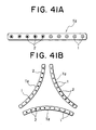
- the fastening device with tape in which the same kinds of fasteners are attached at the same pitch it can be applied to articles of clothing and bags as a normal snap fastener, and further can be applied to a header tape attached along an upper end edge of a curtain by sewing or the like.
- a hanging device for curtains to which an attaching member to be attached to and detached from a curtain runner is attached in a longitudinal direction thereof at a predetermined interval along a side edge of the fastening device with tape as mentioned above.
- the header tape with the fastening device mentioned above in combination with the handing device for the curtains with the fastening device, since it is necessary that the fastening device attached to the header tape and the fastening device attached to the hanging device be mutually engaged and disengaged, one should become a male fastener, while the other is a female fastener.
- the fasteners are arranged at the same pitch
- a clothing for a baby in which a plurality of second members each having a male engaging portion are arranged at a half portion of the same tape in a longitudinal direction thereof and the same number of second members each having a female engaging portion are arranged at the other half portion.
- the fastening device with tape having such as structure can function as an independent product by itself.
- it can be a pull of a slider or a longitudinally-adjustable band or a slide fastener. It can be realized only by the present invention to mount the male fasteners and the female fasteners on the same tape.
- each first member integrally molded on the tape is not always molded in correspondence to a single attachment hole formed in the tape.
- the adjacent two or more attachment holes may be arranged in a widthwise direction of the tape.
- it is possible to obtain various shapes such as large-patterned designs and shapes having various kinds of designs such as animals, automotive vehicles or the like, so that a fastening device rich in a design as well as a strength of adhesion can be obtained.
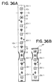
- a plurality of second members may be arranged in a longitudinal direction of the tape at a selected desired interval, in which a second member having a male engaging portion is-arranged in at least one end of the tape, and a plurality of second members comprising male or female fastening members are arranged in a mixed manner, and in which at least one engaging portion other than that of the second member having the male engaging portion at the end of the tape is protruded on the tape surface in an opposite direction to the protruding of the engaging portion of the male second member at the end of the tape.
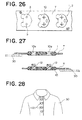
- the fastening device with the tape can be adhered to the clothes by inserting the male fastening member attached to the tape end of the fastening device with tape into a button hole or the like of an opening joining portion of the clothes or the like, and folding the tape back to engage the male fastening member with the opposing female fastening member.
- the other male fastening members protrude on the opposite surface of the tape.
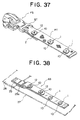
- an fastening device with tape having a second member comprising a base portion to be integrally adhered to the opening portion of the first member, and a ring-like string-passing portion standing from a surface of the base portion.
- the fastening device is attached to a back surface of a curtain in a vertical direction, and a string having a stopper member at its one end is inserted into a plurality of ring-like string-passing holes.
- the curtain can be opened and closed by pulling or releasing the other end of the string member.
- the fastening device with tape along the opening portion of a saccate-like bag, together with a string it can be used as an opening and closing device for the opening portion of the bag.
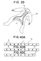
- a fastening device with tape in which the second member comprises a base portion integrally adhered to the opening portion of the first member, and a hook portion standing on a surface of the base portion.
- a female fastener is prepared in which the second member separately manufactured is adhered to the opening portion of the first member in fitted state, and a ring portion stands on a surface of the base portion, by combining the both male and female fasteners, it can be used as a hooking device for, for example, a brassiere, baby clothes or the like.
- each of female and male fasteners of the device has at least a first member and a second member.
- the first member is previously molded integrally to an attachment hole in the tape, and then the second member is attached to an opening portion of the first member.
- the first member can be molded in various shapes as far as it is provided with an opening portion at its center.
- a shape of the second member does not affect the shape of the first member, so that one type of the first members can be commonly applied if the second members are altered with their shapes or materials.
- the second member can be made of material or can be in a color different from that of the first member.
- FIG. 1 is a perspective view of a first embodiment showing a male fastener and a female fastener of an fastening device with tape in accordance with the present invention being integrally mounted on a tape in a parallel manner.
- FIG. 1 As a typical embodiment of the fasteners mounted to the fastening device with tape in accordance with the present invention, there are a female fastener 1 and a male fastener 2. Further, as another example there can be an eyelet, a string-passing device for opening and closing a curtain which will be described later, or the like. Though a basic principle of a method of manufacturing this device is based on a manufacturing method as disclosed in the specification of US patent No. 2,821,764, various shapes and materials can be selected to and various colors can applied to the respective fasteners 1 and 2 each having a characteristic feature according to the present invention, which could not obtained by the invention of the above U.S. patent, while they can be integrally mounted on the tape.
- a plurality of attachment holes 3 are previously formed on a long tape T at a predetermined interval, then the tape T is supplied to a mold. Thereafter, a ring-like base member 10, which is one of constituting members of the female fastener 1 and/or the male fastener 2, is integrally molded on front and back surfaces of the tape T in such a manner as to hold a peripheral edge of the attachment hole 3 by injection molding.
- the base member 10 constitutes a first member in the present invention.
- tape-supporting members pins
- molten resin is introduced to the peripheral edge of the attachment hole 3 substantially in such a manner as to be parallel to the tape T.
- the female or male fastening member 11 or 12 as a second member is integrally molded to the each of the base members 10 integrally molded with the tape T, on the basis of the molding technique described in the US patent as mentioned above.
- an inner peripheral surface of a central opening portion 10a of the base member 10 is formed in a shape as a normal female engaging and disengaging surface, in which case the base member 10 can be used as the female fastener as it is without newly attaching a female fastening member 11.
- the male fastening members 12 are integrally molded on an alternate one of a plurality of base members 10 integrally molded in a longitudinal direction on the same tape T at the same pitch and having a common shape.
- the female fastener 1 and the male fastener 2 are alternately mounted to the same tape T.
- Such arrangement as mentioned above can not be efficiently manufactured by the conventional technique, and it is apparent that the present invention can manufacture a male fastener 2 by utilizing the conventional general female fastener with tape.
- FIG . 2 shows a representative shape of a base member on a tape in accordance with the present embodiment of this invention immediately after the base member 10 is integrally molded to the peripheral edge portion of the front and the back of the attachment hole 3 in the tape T.
- the opening portion 10a of the base member 10 is not completely formed at the center portion thereof.
- an outer shape of the base member 10 wholly shows a flower-like shape in which four arch-like portions are connected at their outer periphery.
- the opening portion 10a is arranged at the center portion, and in an intermediate portion in a direction of the thickness, the attachment hole 3 of the tape T extends near the peripheral edge portion of the opening portion 10a, so that the base member 10 is integrally adhered to the tape T so as to hold the attachment hole 3 of the tape T.
- four molding holes 10b which extend in the direction of the front and the back thereof are formed on the front and back surfaces of substantially the center portion of the arch-like area of the base member 10 by the tape-supporting members, which will be described later, projecting into the cavity.
- the molding holes 10b are formed in such a manner that the tape T crosses the middle thereof.
- a molded runner 14 molded by a molten resin passage of the mold comprising a runner 103a, a sub runner 103b and a gate 106 (see FIG . 6), and a molded gate 16 are simultaneously molded.
- An end of the molded gate 14 is connected to substantially a center of a bottom surface 10c' of a recessed notch portion 10c formed on an inner peripheral surface of the central opening portion 10a of the base member 10.
- the molded runner 14 is automatically broken and separated from the molded gate 16 at a time of opening the mold as mentioned below, and further, the molded gate 16 connected to the base member 10 is automatically broken and removed when engaged with the male fastener 2 as mentioned below, so that the opening portion 10a having a complete shape is formed.
- FIGS. 3 and 4 show a structure of the male fastener 2 with tape which is integrally mounted to the tape T and is provided with all of the characteristic portions of the present invention.
- the male fastener 2 mentioned above is composed of a base member 10 as a first member of the present invention and a male fastening member 12 as a second member.
- the male fastening member 12 is composed of a base portion 12a fitted to and integrated with the opening portion 10a of the base member 10, a column portion 12b standing from the base portion 12a and an engaging head portion 12c comprising an engaging and disengaging portion formed in a front end of the column portion 12b.
- the column portion 12b and the engaging head portion 12c are separated into right and left portions by a split groove 12d extending from a middle of the column portion 12b to a front end of the engaging head portion 12c in an axial direction.
- a whole shape of the head portion 12c including the split groove 12d assumes an oval shape having a shorter diameter portion in a longitudinal direction of the split groove 12d, and is formed in a shape expanding to a lateral direction of the column portion 12d.
- the male fastening member 12 having such a shape as mentioned above is integrally molded so as to be inserted into the opening portion 10a of the base member 10.
- the shape of the molded gate 16 is formed to be a wedge shape as a whole. Accordingly, when inserting the engaging head portion 12c of the male fastening member 12 into the opening portion 10a of the base member 10, as shown in FIG . 5, the molded gate 16 connected and integrated with the opening portion 10a can be simply broken and removed due to an inserting force of the male fastening member 12.
- the gate shape as mentioned above, when sending the male and female fasteners with tapes in an engaged state at a time of their shipping, not only it is possible to omit a trimming process at a later process which was necessary in the invention of the US patent, but also the molded gate 16 can be automatically removed at the same time of engaging the male and female fasteners with tapes.
- the recessed notch portion 10c formed on a part of the inner peripheral surface of the opening portion 10a is formed so as to be recessed toward two opposing molding holes 10b among four molding holes 10b formed by the tape-supporting members, so that the molded gate 16 and the two molded holes 10b are on the same straight line.
- a burr made by breaking and removing the molded gate 16 (a gate burr 16a) is formed on the bottom surface 10c' of the recessed notch portion 10c as mentioned above, so that no burrs do not remain in the peripheral surface 10a' of the opening portion which directly contact with the engaging head portion 12c at a time of engaging and disengaging between the peripheral surface 10a' of the base member 10 as a female fastening member and the engaging head portion 12c of the male fastening member 12.
- a trimming as in the invention of the US patent at the later process can be omitted.
- the gate burr 16a can hardly be seen in appearance.
- the recessed notch portion 10c is significantly effective.
- attachment of the male fastening member 12 to the base member 10 is performed by integral molding.
- a part of the male fastening member 12 fills the recessed notch portion 10c, a locking function between the base member 10 and the male fastening member 12 is additionally achieved, so that a strength of its adhesion is further improved.
- the male fastening member 12 can be molded in the opening portion 10a.
- the molded gate 16 is buried within the male fastening member 12 as a frame member as shown in FIG . 8, it is possible to improve the strength of adhesion. In this case, since the molded gate 16 is not broken and removed from the opening portion 10a, its shape may not be limited to the wedge shape as mentioned above.
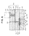
- FIG. 6 shows an example of a mold for integrally molding the base member 10 on the tape T.
- the mold comprises a first mold (a movable mold) 100 and a second mold (a fixed mold) 150, and the first mold 100 is further composed of three-layered plates 101 to 103 relatively movable in a vertical direction.
- the upper plate 101 is a movable side mounting plate provided in a base frame so as to be movable in a vertical direction by a ascending and descending means (not shown) such as a hydraulic pressure cylinder or the like, and the intermediate plate 102 and the lower plate 103 independently move in a vertical direction with respect to the upper plate as a movable side mounting plate 101 in the same manner.
- the second mold 150 is composed of an independent plate fixed to a machine table.
- a substantially upper half of a sprue bush 104 in which a sprue 104a is formed is fitted and fixed to the movable side mounting plate 101 in accordance with a normal method, and a substantially lower half of the sprue bush 104 is slidablly attached in a fitting hole of a stripper plate 102 as an intermediate plate.
- a runner 103a communicated with the sprue 104a is formed in the lower plate 103 so as to be perpendicular to a moving direction of the tape T, and a sub runner 103b extending to a vertical downward direction is formed at an end of the runner 103a.
- a runner lock pin 108 is mounted in the movable side mounting plate 101 and the stripper plate 102 on a line extending from the sub runner 103b.
- a gate 106 horizontally extending via a resin storage portion 105 in a straight manner is formed on a parting surface 151 of the fixed mold 150 as a second mold.
- the gate 106 comprises two right and left portions extending in a straight manner with the resin storage portion 105 being as a center, a shape of each of the gate 106 is formed in a wedge shape.
- the gate 16 is a so-called pin point gate formed such that its cross section becomes smaller from the resin storage portion 105 to its front end.
- the resin storage portion 105 in the present embodiment is a portion of introducing the molten resin
- the gate 106 is a molten resin guiding passage in accordance with the present invention. Accordingly, the molten resin introducing portion to the base-member-molding cavity 107 in accordance with the present invention is a front end portion of the gate 106.
- the front end portion of the gate 106 is connected to the cavity 107 for forming the base member 10 also serving as the female fastener 1.
- the molding cavity 107 is formed in the lower plate 103 and in the fixed mold 150 as a second mold with the parting surface therebetween, and the resin storage portion 105 is partly formed in the fixed mold 150.
- a tape inserting passage 152 extending in a moving direction of the tape T (a direction perpendicular to a sheet surface of FIG . 6) is formed near the cavity 107 of the fixed mold 150.
- the base-member-molding cavity 107 comprises a molding space having a flower-like shape having the gate 106 including a resin storage portion 105 formed in its center, i.e. a solid portion having a substantially circular shape, as shown in FIGS. 4 and 5.
- a resin storage portion 105 formed in its center, i.e. a solid portion having a substantially circular shape, as shown in FIGS. 4 and 5.
- four sets of pins 107a as tape-supporting members are arranged so as to project into the cavity 107 from upper and lower sides thereof at a phase difference of 90 degrees.
- a gap between each set of the upper and lower pins 107a is set to be sufficient for nipping the tape T.
- an inserting hole for an eject pin 153 is formed along an axis of each pin 107a opposing to the gate 106 of the fixed mold 150 in such as manner as to pass the pin 107a through, and the eject pin 153 moves within the pin 107a by an eject-pin-ascending-and-descending means (not shown) in such a manner as to freely slide in a vertical direction.
- a connection portion between the gate 106 and the cavity 107 is disposed on a straight line connecting the gap between each set of the upper and lower pins 107a and the center of the resin storage portion 105, so that the gate 106 is directed to the peripheral edge of the attachment hole 3 in the tape T and the connection portion is formed so as to project into the inner portion of the cavity 107 so that the recessed notch portion 10c locally recessed in the outer diameter direction in a circular shape of the opening portion 10a of the base member 10 is formed.
- an injection nozzle 154 of the injection apparatus is brought into contact with a sprue bush 104 in a state that a whole of the mold is closed, and then an injection is performed.
- the molten resin is introduced into the base-member-molding cavity 107 through the sprue 104a, the runner 103a, the sub runner 103b, the resin storage portion 105 and the gate 106.
- the molten resin introduced into the cavity 107 flows to the peripheral edge of the attachment hole 3 in the tape T from the front end of the gate 106, and fills the whole of the cavity while circulating around the periphery of the pins 107a arranged in such a manner as to oppose in a vertical direction after flowing onto the respective front and the back of the tape T.
- the portion of the peripheral edge portion of the attachment hole 3 on the tape T other than the portions nipped by the pins 107a is buried in and integrated with the molten resin while being slightly corrugated by the fluidizing pressure of the resin.
- the movable side mounting plate 101 and the stripper plate 102 together ascend so as to remove the molded runner 14 together with the molded sub runner 14a from the lower plate 103 while supporting it by the runner lock pin 108. At this time, a lower end of the molded sub runner 14a is broken and separated from an upper end of the molded resin storage portion 15 due to the separating force.
- the stripper plate 102 slightly moves so as to release the support of the molded runner 14 by the runner lock pin 108, thereby separating it together with the molded sprue from the mold.
- the lower plate 103 moves upward so as to open the mold, substantially at the same time, the eject pin 153 slightly moves upward so as to push up the tape T exposed at a middle of the molded hole 10b formed by each supporting pin 107a, thereby pushing out the base member 10 together with the molded gate 16 outside of the mold.
- the base member 10 at this time has such a shape as shown in FIG. 2, after the molded sub runner 14a is broken and separated as shown by an imaginary line in FIG . 2.
- the molded gate 16 left in the base member 10 is connected at a slight portion to the bottom surface 10c' of the recessed notch portion 10c formed in the opening portion 10a of the base member 10, it can be automatically broken and removed when engaged with the engaging head portion 12c of the male fastener 2 as mentioned above.
- the breakage burr of the molded gate 16 (the gate burr 16a) formed at the this breaking is formed on the bottom surface 10c' of the recessed notch portion 10c, it can hardly be seen from outside. Further, since the burred surface is not formed on the inner peripheral surface 10a' of the opening portion 10a to be directly engaged with and disengaged from the engaging head portion 12c of the male fastener 2 and since a part of the circular inner peripheral surface 10a' is separated by the recessed notch portion 10c, its engagement and disengagement with respect to the male fastener 2 can be more smoothly performed.
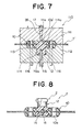
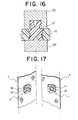
- FIG . 7 shows a main portion of a mold for integrally molding the male fastener 2 on a tape T' with a base member obtained by molding and integrating the base member 10 having a shape as mentioned above.
- the base member 10 constitutes a first member in accordance with the present invention
- the male fastening member 12 integrally molded on the inner peripheral surface 10a' of the opening portion 10a in the base member 10 constitutes a second member.
- This kind of fastening device with tape is generally mounted along an opening and closing portion of each of various products comprising various fabrics, synthetic resin sheets, leather, non woven fabrics or the like.
- a thermal set is performed by an expert at each of the products, so that a temperature of thermal set is strictly controlled and no special problem is generated.
- many kinds of products tend to be simultaneously ironed, and some products are ironed at a temperature equal to or more than a proper ironing temperature.
- polyacetal resin is generally is employed.
- the polyacetal resin has a low melting point which is 179 °C even in a homopolymer having a higher melting point than copolymer thereof.
- the ironing temperature for finishing the normal clothes or the like frequently becomes equal to or higher than the melting point, so that when the iron set at the temperature equal to or higher than the melting point of material of the clothes is erroneously brought into contact with the fastener, especially with the male fastener having an engaging head portion protruding from the tape surface, it is easily softened or melted and the engaging head portion is deformed or press broken. As a result, the engaging and disengaging function as well as the outer appearance is lost.
- the iron functions such that the finishing temperature can be altered at some steps in accordance with the material of the product to be finished.
- the ironing temperature is set to a high temperature of substantially 190 °C.
- the ironing temperature is set to a medium temperature of substantially 160 °C in a case of animal fiber such as sheep wool, silk or the like, or synthetic fiber having relatively high finishing temperature such as nylon, polyester or the like, and it is set to a temperature of substantially 100°C in a case of the fiber product made of acrylic resin, polyurethane and the like which is necessary to be finished at a low temperature.
- the finishing temperature of the product by the iron is higher than the melting point of the fastener
- the fastener is melted or softened so as to be easily deformed. If the deformation is given only at the base material portion mentioned above, a damage is only on the outer appearance. However, when the deformation is given in the male fastening member 12, the basic engaging function as the male fastener is lost.
- the base member 10 in accordance with the present invention can be also used as a female fastener 1, in manufacturing the fastening device with tape in accordance with the present invention, the base member 10 can be commonly molded with respect to all the male and female fasteners, so that it is preferable to use material which is not affected by environment as much as possible and is easily molded on the tape for the base member 10. Accordingly, in the present embodiment, polyacetal resin is used for the base member 10 and polyamide resin such as nylon 6, nylon 66 or the like is used for the male fastening member 12.
- the material of the base member 10 is largely affected also by the material of the tape.
- the tape can employ significantly various kinds of materials, for example, such as a fiber tape constituted by natural fiber such as cotton, sheep wool or the like or synthetic fiber such as polyamide, polyester, polypropylene or the like, and synthetic resin film made by polyamide, polyester, polyvinyl chloride, polyethylene or the like.
- a tape strechable material, a very super thin tape or the like may be used in accordance with the structure of the product.
- the present invention does not limit the material to those as mentioned above, and all thermal plastic synthetic resins can be employed.
- the typical resin material to be applied to the base member 10 is exemplified by polyacetal resin, polyvinyl chloride, polyvinyl acetate, various kinds of polyamide, polyester or the like, while the typical resin material to be applied to the male fastening member 12 is exemplified by a polyamide resin, polyethylene terephthalate, polybutylene terephthalate, polymethyl pentene, polyphenylene oxide, polycarbonate, polypropylene or the like.
- inorganic additive such as fine particle of metal and ceramic, glass fiber, carbon fiber, aramide fiber or the like may be mixed in the thermoplastic resin material as mentioned above.
- inorganic additive it is preferable to add a fine amount of , for example, 10 wt % or less without deteriorating an elasticity of the male fastening member.
- the melting point of the resin material is as shown in TABLE 1.
- FIG . 7 shows a manner in which the mold is closed when integrally molding the male fastening member 12 with the base member 10.
- reference numeral 110 denotes an injection mold for forming the male fastening member, and the mold 110 is provided with a movable mold 111 and a fixed mold 112 in the same manner as the injection mold for molding the base member as previously mentioned.
- a tape-with-base-member-receiving space portion 113 which fittedly receives the base member 10 and the tape T integrally formed with the base member 10 as a center, and there is formed a male-fastening-member-molding cavity 114 which is connected to the tape-with-base-member-receiving space portion 113 so as to cover and fill a central opening portion 10a of the base member 10 with the base portion 12a of the male fastening member 12, including the column portion 12b and the engaging head portion 12c.
- a gate 111a communicated with a runner is formed in the movable mold 111 in such a manner as to communicate with a center portion of a base-portion-forming portion 114a in the male-fastening-member-molding cavity 114, while a slide passage 112a of a slide core 115 for dividing the column portion 12b and the engaging head portion 12c of the male fastening member 12 into two portions is formed in the fixed mold 112.
- the slide passage 112a is formed in such a manner that the slide core 115 can slide in acrossing direction of the fixed mold 112.
- an eject pin 116 to be brought into contact with an outer surface of the base member 10 is provided in an inner portion of the tape-with-base-member-receiving space portion 113 of the fixed mold 112 and at a portion in which the base member 10 is received so that the eject pin 116 can freely ascend and descend.
- the tape T' with base member integrally molded thereto at the peripheral edge portion of the attachment hole 3 in the tape T is inserted and set within the injection mold as structured in the manner mentioned above.
- a basically different point of the structure from the base member 10 as a female fastener exists in that the male fastening member 12 as the second member of the present invention is molded and integrated with the opening portion 10a of the base member 10. That is, the opening portion 10a is closed by the base portion 12a of the male fastening member 12, and the column portion 12b and the engaging head portion 12c to be engaged with and disengaged from the opening portion 10a of the base member 10 as a female fastener are provided so as to project from one surface of the base portion 12a.
- the fastening member 12 comprises the column portion 12b directly standing from the base portion 12a covering the opening portion 10a of the base member 10 and the engaging head portion 12c connected to the front end of the column portion 12b, as mentioned above, and is divided into two portions by a split groove 12d extending from a portion near a standing end portion of the column portion 12b to the engaging head portion 12c.
- a shape of the split groove 12d is determined in accordance with a vertical cross sectional shape of the slid core 115. As is apparent from FIG . 7, a bottom surface of the groove 12d is formed in a circular arc surface, a narrow groove portion and a wide groove portion are continuously formed via an arch-like step portion from the circular arc surface to the end portion of the engaging head portion 12c.
- its elastic deformation can be performed larger than that having the conventional split shape, so that an engaging and disengaging operation with respect to the female fastener 1 can be easily performed, and a desired engaging and disengaging force can be secured.
- the molten resin is injected at a desired injection amount, and is introduced into the cavity 114 for forming the male fastening member through the gate 111a.
- the movable mold 111 ascends and the molded male fastening member 12 and the molded gate 26 are broken and separated.
- the slide core 115 is also operated.
- the eject pin 116 is operated so as to push out the male fastener 2 comprising the base member 10 and the male fastening member 12 from the fixed mold 112.
- the engaging head portion 12c is elastically deformed at a part of the column portion 12b and the engaging head portion 12c by the existence of the split groove 12d therebetween, so that the male fastener 2 can be easily pushed out of the mold.
- the male fastening member 12 in a case of molding the male fastening member 12 to the base member 10, it is possible to differentiate colors of the base member 10 and the male fastening member 12, so that it is possible to manufacture a male fastener with tape which is rich in a design property.
- the same reference numerals denote the members and elements corresponding to the embodiment mentioned above.
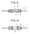
- FIGS. 9 and 10 are schematic views showing a typical embodiment of a female fastener with a tape in which the female engaging member 11 as a second member is integrated and molded with the base member 10 as a first member in accordance with the present invention.
- FIG. 9 is a cross sectional view when the base member 10 is integrally molded with the peripheral edge portion of the attachment hole 3
- FIG . 10 is a cross sectional view of the female fastener with the tape obtained by molding and integrating the female fastening member 11 as a second member with the base member opening portion 10a of the tape T' with the base member.
- the base member 10 in accordance with the present embodiment is different from the embodiment mentioned above, in that a multiplicity of concave and convex portions (uneven portion) are formed on the inner peripheral surface 10a' without forming the inner peripheral surface 10a' of the opening portion 10a to be an engaging surface with respect to the opposing male fastener 2. Due to the uneven surface, when the female fastening member 11 is molded as shown in FIG . 10, a part of the female fastening member 11 is molded along the uneven surface, which can thus form a firm adhesion surface.
- the embodiment is obtained by the molding method on a basis of substantially the same shape and arrangement of the sprue and the gate as in the embodiment for molding and integrating the male fastening member 12 as shown by an imaginary line in FIG . 9.
- the fastening device with tape which is rich in a design property can be manufactured by differentiating the colors of the base member 10 and the male fastening member 12.
- the base member 10 may be molded by hard material while the female fastening member 11 is molded of material softer and smaller in a coefficient of friction than those of the base member 10 as the first member, so that an adhesion portion between the tape T and the female fastener 1 is made firm and a desired engaging force can be obtained and a smooth engaging and disengaging operation can be performed with respect to the opposing male fastener 2.
- the material of the first member and the second member of the opposing male fastener 2 are selected in the same manner as the above female fastener 1, the same function as that mentioned above can be obtained.
- the coloring is generally performed by mixing pigment with the respective resin material.
- the material which can be dyed by dyestuff is selected for the first member, it is possible to dye together with the tape T by the same dyestuff after molding the first member on the tape T.
- the dyestuff which can not be dyed on the tape but dyed on the first member is selected, it is possible to differentiate the color of the tape T and the color of the first member.
- the first member when the first member can be dyed, for example, it is possible to apply dying to a desired amount of the first members on the tapes as demanded after manufacturing a large amount of tapes with the first members in which colorless first members are previously integrally molded on the respective tapes T, so that an efficient manufacturing and product control can be performed.
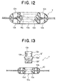
- FIGS. 11 and 12 respectively show a preferred embodiment of a shape of support pins protruding into the cavity for molding the base member in the mold from the upper and lower sides thereof in an opposing manner in the case of integrally molding the base member 10 with the attachment hole 3 of the tape T, and an example of a typical cross sectional shape of the base member 10 in use of the mold.
- the support pin 107a is substantially formed in a conical trapezoidal shape protruding in a direction of approaching to each other, and arranged at a phase difference of 180 degrees or a phase difference of 90 degrees with each other on the same circumference of each of the bottom surfaces of the ring-like base-member-molding cavity 107.
- the pin is formed in a simple conical trapezoidal shape, however, in accordance with the present embodiment, a part of the front end portion of the support pin 107a is formed to be the taper surface 107a' as shown in FIG . 11. Further, the taper surface 107a' is formed in such a manner that when the peripheral edge portion of the attachment hole 3 in the tape T is nipped by the support pin 107a, an interval between the peripheral edge portion of the attachment hole 3 and the front end portion of the support pin 107a becomes gradually greater toward a center of the attachment hole 3.
- each support pin 107a in a plan view of each support pin 107a, a half of an end surface of the support pin 107a is made to be a flat surface 107a" to firmly nip the tape T, and the remaining end surface is formed to be a taper surface 107a'.
- This taper surface 107a' is a corrugation control portion in accordance with the present invention, and serves to suitably control the corrugation in the peripheral edge of the tape attachment hole 3. It is preferable that an taper angle of the taper surface 107a is about 5 to 45 degrees, and more preferably 10 to 25 degrees.
- a portion of the flat surface 107a" as a front end nipping portion in accordance with the present invention is designed so as to be positioned in the outer peripheral edge side from a substantially center point on the straight line connecting the support pin 107a and the outer peripheral edge of the base-member-molding cavity 107 which nips the tape T with the attachment hole 3 being a center.
- the taper angle is determined depending on flexibility of the tape T.
- the description is given to the embodiment in which the male or female fastening members 11 or 12 as the second member is integrated with the base member 10 as the first member by molding.
- the method of integrally mounting the second member to the first member in accordance with the present invention includes various mounting methods other than the integral molding.
- FIGS. 13 and 14 show an example of such other mounting method.
- a male fastening member 12' as the second member similar to the male fastening member and having a base portion 12a', a column portion 12b and an engaging head portion 12c are previously formed.
- a shape of the male fastening member 12' is substantially similar to the fastening member 12, however, a tapered blind hole is simultaneously formed at a center of an end surface of the base portion 12a'. Then, after the male fastening member 12' preliminarily molded in this manner is inserted into the opening portion 10a of a base member 10, a conical projecting portion 131 of a heated body 130 shown by an imaginary line in FIG .
- the male fastening member 12' is engaged and integrated with the opening portion 10a together with a flange portion 12a" of its base portion 12a'.
- FIG S. 15 and 16 show an example of the other mounting method by an ultrasonic wave.
- the male fastening member 12' having the same shape as mentioned above is previously molded. Then, the male fastening member 12' is inserted into an opening portion 10a of a base member 10, and next, a column portion 12b and an engaging head portion 12c of the male fastening member 12' are fitted into an engaging-head-portion-fitting hole 132a of an anvil 132 in the manner shown in FIG . 15, thereby being brought the anvil 132 into contact with the flange portion 12a" of the base portion 12a' of the male fastening member 12.
- a conical projecting portion 133a of a horn 133 is inserted into the central blind hole in the end surface of the base portion 12a' as shown in FIG. 16 so as to oscillate ultrasonic wave, thereby deforming the base portion 12a'. Further, a boundary surface between the inner peripheral surface of the opening portion 10a of the base member 10 and an outer peripheral surface of the base portion 12a' is melted, so that both of them are integrated by welding.
- the base portion 12a of the male fastening member 12 may be inserted into the opening portion 10a after an adhesive is applied to the peripheral surface of the base portion 12a of the male fastening member 12 or the inner peripheral surface of the opening portion 10a on the base member 10, thereby bonding and integrating by the adhesive.
- FIGS. 17 to 19 show an embodiment of molding and integrating the first member and the second member with different materials in accordance with the present invention.
- materials of both of the base member 10 as the first member and the female and male fastening members 11 and 12 as the second member are differentiated, and colors of the base member 10 and the female and male fastening members 11 and 12 are also differentiated. That is, normal thermoplastic synthetic resin is used for the base member 10, while elastomer resin material having elasticity is used for each of the female fastening member 11 and the male fastening member 12. Further, a pigment having a different color or the like is mixed in the synthetic resin material of each of the base member 10, the female fastening member 11 and the male fastening member 12.
- the female fastening member 11 is formed in a ring shape in the same manner as the female fastening member as mentioned above, and has on the inner peripheral surface an engaging surface to be engaged with the opposing male fastening member 12.
- a shape of the male fastening member 12 is different from the shape mentioned above. That is, as shown in FIGS. 18 and 19, a split groove 12d is not formed in the column portion 12b and the engaging head portion 12c standing from the base portion 12a. Accordingly, the female and male fasteners 1 and 2 in accordance with the embodiment are elastically engaged and disengaged with each other. When the split groove 12d is not provided in the column portion 12b and the engaging head portion 12c, the fastener is not caught in a thread or a hair at the time of its engaging and disengaging, so that a smooth engaging and disengaging can be performed.
- the male fastening member 12 is soft and has elasticity as mentioned above, its connection with the inner peripheral surface 10a' of the central opening portion 10a of the base member 10 becomes unstable in the engaging and disengaging operation between both female and male fasteners 1 and 2.
- an unstable connection between the base member 10 and the male fastening member 12 can be prevented by setting a total area of bulging portions 12' in plan view each existing respectively at the right and left portions of the male engaging head portion 10c which engages with and disengages from the female fastener 1, at a predetermined size.
- the total area of the bulging portions 12' is set to be smaller than a difference between a total area, in plan view, of a diametrically enlarged portion of the base portion 12a of the male fastening member 12, i.e. the largest area S 1 , and an area S 2 , in plan view, of a narrowed portion of the male fastening member 12 because of the existence of the inner peripheral surface 10a' of the central opening portion 10a of the base member 10, as shown in FIG. 18.
- FIGS. 20A to 20D show an embodiment in which a first member as a ring-like base member 10 is a molded product for applying a rigidity sufficient to restrict corrugation in the peripheral edge of the attachment hole, which is most easily corrugated, to a minimum degree at the time of molding and integrating the second member.
- the outer peripheral portion of the ring-like base member 10 is made thick and the portion extending from the outer peripheral portion to the central opening portion is formed thin.
- the thick portion 10d formed in the outer peripheral portion constitutes an outer edge portion of the fasteners 1 and 2 as a final product, and the thin portion 10e extending from the outer peripheral portion to the central opening portion becomes a frame member buried within a second member at the next process.
- FIG. 20C shows an embodiment of the female fastener 1 in which the female fastening member 11 as a second member is integrally formed on the peripheral surface 10a' of the opening portion of the base member 10 molded and integrated with the tape T, the front and back surfaces of the thin portion 10e and the inner peripheral surface of the front and back thick portions 10d
- FIG. 20D shows an embodiment of the male fastener 2 molded and integrated in a state that the male fastening member 12 as a second member is fitted to and molded integrally with the peripheral surface 10a' of the opening portion in the base member 10 molded and integrated on the tape T, the front and back surfaces of the thin portion 10e and the inner peripheral surface of the front and back thick portions 10d.
- this fastening device with tape, at first, as shown in FIG . 20A, the attachment hole 3 is previously formed on the tape T and the base member 10 having a shape as mentioned above is integrally molded on the tape T (see FIG . 20B).
- the female or male fastening member 11 or 12 as a second member is molded and integrated in a range from the inner peripheral surface 10a' of the central opening portion 10a of the base member 10 to an inner peripheral surface 10d' of the thick portion 10d in the same manner as mentioned above.
- the product shown in FIGS. 20C and 20D can be obtained.
- the cavity for molding male fastening member 12 is a shape in which a deep recessed notch portion 12f is formed at the center portion of an end surface of a base portion 12a of the male fastening member 12, and dispose a gate 106 at a center of the recessed notch portion 12f, as shown by the imaginary line in FIG. 20D.
- the present invention may be such a structure that an intermediate member is additionally interposed between the first and second members.
- the intermediate member is not limited to a case of being constituted by a single layer as mentioned below, but can be constituted by a plurality of layers.
- FIG s. 21A and 21B show an embodiment in which an intermediate member 13 is composed of one layer.
- a ring-like base member 10 having a thick portion 10d and a thin portion 10e is integrally molded to the peripheral edge portion of the attachment hole 3 previously formed in the tape T.
- the tape support pins are not arranged within the cavity.
- the thin portion 10e of the base member 10 may only have a minimum thickness enough to secure such rigidity that an peripheral edge portion of the attachment hole in the tape T after molded does not largely corrugate due to the pressure of the molten resin introduced into the cavity at the time of molding the intermediate member 13.
- the base member 10 as the first member is provided as a molded product for applying a rigidity sufficient to restrict the corrugation in the peripheral edge portion of the attachment hole, which is most easy to become corrugated on the tape T, not only the intermediate member 13 is easy to be molded, but also different colors can be applied to the base member 10 as the first member, the intermediate member 13 and the male fastening member 12 as the second member.
- FIGS. 22 to 24 show an embodiment of an fastener with tape having another engaging structure in accordance with the present invention.
- the female fastener 1 of the fastening device with tape in accordance with this embodiment can commonly serve as a first member of the present invention, likewise the embodiment as shown in FIG. 2.
- an engaging portion 1b to be engaged with and disengaged from an opposing male fastener 2 along one inner peripheral edge on one of the front and back sides of the central opening portion 10a.
- the engaging portion 1b bulges out from the inner peripheral surface 10a' and toward the central direction of the central opening portion 10a, and has a plurality of notch portions 1c arranged at a predetermined interval in a peripheral direction thereof. Since the engaging portion 1b slightly deforms in an elastic manner in a radial direction because of the existence of the notch portion 1c, its engagement and disengagement with respect to an opposing engaging head portion 12c as mentioned below can be smoothly performed.
- the opposing male fastener 2 is molded on a first member which is identical with the female fastener 1 in accordance with the present invention. That is, as is apparent from FIG . 22, the male fastening member 12 is integrally molded with the central opening portion 10a of the first member which can be a female fastener 1 in accordance with the method mentioned above.
- the male fastening member 12 since a part of the male fastening member 12 enters into notch portions 1c formed as mentioned above in the female fastener 1 so as to be integrated therewith, a strength of adhesion between the first member and the male fastening member 12 as the second member is increased. As a result, a desired strength of adhesion can be obtained, for example, even between the resins having small affinity.
- a column portion 12b and the engaging head portion 12c of the male fastening member 12 may only be formed in a hollowed cylindrical shape with the engaging head portion 12c bulging outward, as shown in FIG. 22.
- a split groove 12d is not formed in the male fastening member 12 as previously mentioned, an engagement and disengagement between the female fastener 1 and the male fastener 2 can be smooth, while an engaging and disengaging force sufficient to be durable in a practical use can be secured. Further, since no split groove is formed, any thread or hair is not caught at a time of engaging and disengaging the fasteners.
- FIG. 25 shows a shape of the first member (the base member 10) of the fastening device with tape, as an article, decoratively designed in accordance with the present invention.
- the first member the base member 10
- FIGS. 25A and 25B show a fastener with tape having an fastener 1 or 2 obtained by the embodiment mentioned above as shown in FIG s. 22 and 23.
- the female and male fasteners 1 and 2 designed in this manner are particularly preferable to the clothes or bags for babies.
- the female and male fasteners 1 and 2 to be engaged and disengaged with each other are respectively mounted to the same first members 10.
- the present invention may include such a case that two or more female and/or male fasteners 1 and 2 are respectively mounted to the same first members.
- FIGS. 26 to 28 show the case of mounting two or more female or male fasteners 1 and 2 to the first members designed in the same decorative shapes.
- each article is decoratively designed to be a face of a bear, and this device can be mounted to front open portions of the clothes 30 for babies as shown in FIG. 28.
- a strength of engagement sufficiently to be durable in a active motion of the baby can be achieved.
- a plurality of attachment holes 3 are formed on the same tape T in a longitudinal direction thereof at a predetermined interval and are arranged in two rows in parallel in a widthwise direction of the tape T.
- a single first member 10 which is designed in the face of a bear is integrally molded on the tape T in such a manner that the attachment holes 3 adjacent in a widthwise direction of the tape correspond to right and left eyes of a bear.
- the female or male fastening members 11 or 12 is integrally molded with opening portions 10a corresponding to the right and left eyes.
- a remarkably decorative fastener can be obtained by mixing pigment or the like in the resin material for the fastening members 11 or 12 and molding with colors different from that of the resin material of the first member 10.
- FIGS. 29 and 30 show an embodiment in which resin material having magnetism are used for both of the female and male fastening members 11 and 12 so that the female and male fasteners 1 and 2 can be engaged and disengaged by a magnetic force.
- powder of ferrite magnet are mixed in the resin material for each of the female and male fastening members 11 and 12, which are respectively molded and integrated with a central opening portion 10a of the base member 10 as a first member. This can be achieved by only setting an engaging portion 11b of the female fastening member 11 to be a recessed notch portion formed in a simple circular cross sectional shape, and an engaging portion 12h of the male fastening member 12 in a cylindrical shape to be fitted to the female engaging portion 11b.
- FIG . 31 shows an embodiment which also utilizes a magnetic force for an engaging and disengaging force of the female and male fasteners 1 and 2.
- an intermediate member 13 is interposed between the male fastening member 12 and the base member 10.
- the intermediate member 13 is made of resin in which powder of the ferrite magnet are mixed, and has a ring-like shape having an opening portion 13a at its center, which is integrally molded with an opening portion 10a of the base member 10 in the same manner as that of the embodiment mentioned above.
- the male fastening member 12 is integrally molded with the opening portion 13a of the intermediate member 13, thus a male fastening device with tape is completed.
- the male fastening member 12 is narrowed at its base portion 12a and has a simple cylindrical engaging portion 12h, with no engaging head portion bulging at its periphery, standing from the intermediate member 13 so as to be molded and integrated therewith.
- a plurality of colors can be applied to a single male fastener 2 by mixing pigment having different colors in the resin materials for, particularly the first member (the base member) 10 and the intermediate member 13.
- FIGS. 32 and 33 shows a case that an fastening device with tape in accordance with this invention is provided with a structure which can be freely attached to and detached from the clothes so that the tape T with device is used a single female or male button fastener 31 or 32.
- the fastener with tape is a female button fastener 31, in which the tape T made of natural or synthetic leather is formed in a rectangular shape.
- a press line P1 is formed so as to make an intermediate portion of the tape T in a longitudinal direction foldable, and a rectangular press line P2 is formed along an peripheral edge of each of left and right small pieces T1 and T2 defined by the press line P1. It is not necessary that a shape of the rectangular press line P2 is formed in a rectangular shape.
- an optional pattern can be formed by the press line P2.
- two female fasteners 1 are mounted to one of the left and right small pieces T1 and T2, and a male fastener 2 is integrally mounted to an end portion of the other.
- FIG. 33 shows a case that the fastener with tape is a male button fastener 32, the tape T is made of natural or synthetic leather formed in a rectangular shape, a press line P1 is formed so as to make an intermediate portion of the tape T in a longitudinal direction foldable while a rectangular press line P2 is formed along a peripheral edge of left and right small pieces T1 and T2 defined by the press line P1, in the same manner as the female button fastener. Then, one female fastener 1 and one male fastener 2 can be respectively integrally mounted to one of the left and right small pieces T1 and T2, and one male fastener 2 is integrally mounted to an end portion of the other small piece.
- FIGs. 34 and 35 show a manner in which each of the female and male button fasteners 31 and 32 are attached to clothes or the like, and each of the button fasteners 31 and 32 is used as a fastener device for the clothes.
- an insertion hole through which an engaging portion 12i of the male fastening member 12 is to be inserted is previously formed in the button-fastener-attachment portion of the clothes or the like.
- the female button fastener 31 is folded along the press line P1 as a folding line, and the engaging portion 12i of the male fastener 2 mounted to the end portion of the female button fastener 31 is inserted into the insertion hole so as to be engaged with a corresponding female fastener 1.
- the female button fastener 31 is attached in this manner, one of two female fasteners 1 attached in parallel is exposed on one of opposite joining portions of a front opening portion of the clothes. This female fastener 1 serves as a female button fastener.
- the base member 10 as a first member is molded so as to have a function of a female fastener 1
- Such options can be made possible only by the present invention.
- FIGS. 36 and 37 shows an example in which the fastening device with tape in accordance with the present invention is used as a pull of a slider of a slide fastener
- FIG . 38 shows an example in which the fastening device with tape in accordance with the present invention is used a freely-adjustable fastening band AB to be used for bags.
- the fastening device with tape in accordance with the present invention can be manufactured efficiently for various uses, as in the same manner as shown in FIGS. 32 and 33.
- the fastening device with tape having a shape shown in FIG . 36 can be also used as a hanging device for a bag or the like, for example, when being attached to a hand portion of the bags in the same manner as a pull for the slider.
- a pull PT for a slider of a slide fastener as shown in FIG. 36 is manufactured with a fastening device with tape in accordance with the present invention
- the base members 10 as first members are integrally molded at all of a plurality of attachment holes formed in the long-sized tape T at a predetermined pitch
- a male fastening member 12 is integrally molded to an opening portion 10a of one base member 10 in the end portion side among a desired number (four in the illustrated embodiment) of base members 10.
- the fastener with the long-sized tape manufactured in the above manner is cut along a cutting line CL as shown by an imaginary line in FIG . 36A. Prior to this cutting, as shown in FIG.
- the end portion of the tape T to which the male fastener 2 of the tape T is attached is inserted into a pull ring ST of a slider FS so as to be folded back, and the male fastener 2 is engaged with the opposing female fastener 1 so as to form a pull PT, as shown in FIG . 37.
- FIG . 38 shows an example in which the fastening device with tape in accordance with the present invention is applied as a fastening band AB which is freely adjustable for fixedly closing an opening portion of a main body of a bag or the like with its opening and closing cover.
- a fastening band AB which is freely adjustable for fixedly closing an opening portion of a main body of a bag or the like with its opening and closing cover.
- an end of the tape T with a male fastener 2 manufactured in the same manner as the example as mentioned above is attached to the bag main body 27 by sewing or the like.
- An end portion of a band 29 having a connection ring 29a at one end thereof is attached to an opening and closing top cover 28 of the opening portion of the bag main body 27 by sewing or the like.
- FIG . 39 shows rompers 33 to which the fastening device with tape in accordance with the present invention is applied.
- the rompers 33 has a front body and a leg portion which are continuously opened and closed in a range from a neck portion to right and left knee portions thereof as shown in the drawing.
- the male and female snap fasteners are attached along the front open portion thereof so as to join the right and left portions.
- Each interval between the snap fasteners is frequently changed in accordance with their mounting portions, and in most cases, an arrangement of the male and female fasteners is not uniform.
- FIG. 40A shows an example of an fastener Ta with tape in which the female fasteners 1 and the male fasteners 2 are arranged on the same tape and are divided into groups in a longitudinal direction thereof, one of the intervals being made different.
- FIG. 40B shows an example of a fastener Tb with tape in which the male fasteners 2 all of which are the same kind are arranged on the same tape at the same arrangement interval as mentioned above.
- FIG. 40C shows an example of an fastener Tc with tape in which the female fasteners 1 all of which are the same kind are arranged on the same tape at the arrangement interval as mentioned above.
- These fasteners Ta to Tc with tapes are excellent in engaging and disengaging operation when they are attached along the front open portion of the rompers 33 as shown in FIG . 39 and can constitute an engaging and disengaging portion gentle for a sensitive skin of babies.
- FIG. 41A shows an example of a fastener Td with tape in which five female fasteners 1 are arranged on a half portion of the tape T in a longitudinal direction thereof as being integral thereto, while five male fasteners 2 are arranged on the remaining half portion of the tape T as being integral thereto.
- the fastening devices with this structure can sufficiently serve as buttons for opening and closing the rompers 33 only by attaching three fasteners Td with tapes, as illustrated in FIG. 44B, along the front opening portion of the rompers 33 by sewing or the like.
- FIG. 42 shows an example in which the fastening device with tape in accordance with the present invention is used as a header tape 35 to be attached along an upper end edge of a curtain 34 as it is and the fastening device with tape in accordance with the present invention is set as a curtain hanging tape 36.
- a base member 10 as a first member of the present invention has a rectangular configuration, and has an opening portion at the center portion thereof so as to function also as a female fastener.
- the base member 10 is used as the female fastener, and a male fastening member 12 is integrally molded to the base member 10 of the curtain hanging tape 36 so as to form the male fastener 2.
- the attaching member 37a may be made of metal material.
- FIG . 43 shows an example in which a second member in accordance with the present invention is formed in a hook shape.
- ring-like base members 10 having an opening portion 10a at a center portion thereof are integrally molded at both ends of the fastening device with tape in accordance with the present invention.
- a hook-like male fastening member 17 is integrally molded to the opening portion 10a of one of the base members 10.
- FIG . 44 shows a manner in which the fastening device with tape having such a structure as mentioned above is used as a hanging tape 38 for a picture.
- a hook member 39 attached on a lintel or a long closet is inserted into the opening portion 10a of the base member 10 molded to an upper end of the hanging tape 38, and a hanging ring 40 for a picture or he like is hooked by a hook-like portion of the male fastener 2 having the male fastening member 17 and formed at a lower end of the tape 38, thereby hanging the picture.
- FIGS. 45 and 46 show an example of a curtain opening and closing tape 41 in which a string-passing member 19 having a ring portion 19c as a second member in accordance with the present invention is integrally molded with an opening portion 10a of a base member 10 as a first member molded on a tape T.
- the base member 10 in a rectangular shape having an opening portion 10a at a center portion thereof is attached to an attachment hole 3 which is previously formed in the tape T by integral molding as shown in an upper left side of FIG . 45, and then the string-passing member 19 is molded to the opening portion 10a of the base member 10.
- the string-passing member 19 comprises, as is apparent from FIGS.
- a plate-like small piece having a base member 19a integrally molded to an inner peripheral surface of the opening portion 10a, a ring portion 19c standing outwardly from the opening portion 10a and having a string-passing hole 19b opening in a longitudinal direction of the tape.
- a plurality of curtain opening and closing tapes 41 each provided with such a structure as mentioned above are arranged in parallel on a back surface of the curtain 34 in a vertical direction by sewing or the like, with the ring portion 19c being exposed outside.
- a string member 42 is inserted toward each of the string-passing holes 19b of the ring portion 19c so as to suspend an upper end of each of the string members 42 from a portion near to right and left end edge portions of the curtain 34 via a guide member 44 comprising a ring or a pulley fixed along a curtain box 43 or the like as shown in FIG. 47.
- a stopper 42a is attached to a lower end of the string member 42, thereby preventing a suspending end of the string member 42 from being pulled out from the string passing hole 19b of each of the ring portions 19c when the suspending end is pulled.
- the curtain 34 is pulled up from its lower end portion while forming pleats, as shown in FIG . 48, In this state, when the suspending end of the string member 42 is released, the suspending end is taken up in a direction of the stopper 42a due to a weight of the curtain 34, so that the curtain 34 is closed.
- the tape with the fastener in accordance with the present invention is used as a curtain opening and closing tape 41, it may be used as an opening and closing tape for a sccate type bag when it is attached in the same manner to an opening portion of the sccate type bag.
- the illustrated embodiment only shows a typical embodiment of the opening and closing tape.
- FIGS. 49 and 50 show an example of a tape T to which an fastener having a shape different from that of the fasteners in accordance with the embodiments as mentioned above is adhered.
- a female fastener 21 in accordance with the embodiment as shown in FIG . 49B there are a base member 210 as a first member formed in a rectangular frame shape and a female fastening member 211 as a second member with its base portion 211a being integrally molded with a central opening portion 210a of the base member 210.
- the female fastening member 211 has , as is apparent from FIG s.
- a shape that a female engaging portion 211b projecting from one surface of a base portion 211a formed in a rectangular shape is in a gate-like shape as seen in a longitudinal direction of the tape T and has a side wall 211b' at its back portion.
- the male fastener 22 has a male fastening member 212 as a second member integrally molded at its base portion 212a with a central opening portion 210a of the base member 210 formed in the rectangular frame shape.
- the male fastening member 212 has, as is clearly shown FIG . 49A, such a shape that a male engaging portion 212b projecting from one surface of the base portion 212a in a normal rectangular shape and constituting a hook portion forms an inverted L shape as seen from a side portion of the tape T.
- the hook portion of the male engaging portion 212b engages with and disengages from the gate-shaped portion of the female engaging portion 211b, as shown in FIG. 50.
- the female engaging portion 211b and the male engaging portion 212b of the fastening device with tape in accordance with the embodiment is preferably made of hard material and set its projecting height to be as low as possible.
- the device can be used as the fastener for underwear, brassiere, baby clothes or the like.
Landscapes
- Engineering & Computer Science (AREA)
- Manufacturing & Machinery (AREA)
- Mechanical Engineering (AREA)
- Textile Engineering (AREA)
- Slide Fasteners, Snap Fasteners, And Hook Fasteners (AREA)
- Curtains And Furnishings For Windows Or Doors (AREA)
Applications Claiming Priority (4)
| Application Number | Priority Date | Filing Date | Title |
|---|---|---|---|
| JP13872298 | 1998-05-20 | ||
| JP13872298A JP3591568B2 (ja) | 1998-05-20 | 1998-05-20 | テープ付き係脱具及びその製造方法 |
| JP21311398A JP3652127B2 (ja) | 1998-07-28 | 1998-07-28 | テープ付き雄係脱具とその製造方法 |
| JP21311398 | 1998-07-28 |
Publications (2)
| Publication Number | Publication Date |
|---|---|
| EP0966896A1 EP0966896A1 (en) | 1999-12-29 |
| EP0966896B1 true EP0966896B1 (en) | 2003-07-02 |
Family
ID=26471702
Family Applications (1)
| Application Number | Title | Priority Date | Filing Date |
|---|---|---|---|
| EP99108551A Expired - Lifetime EP0966896B1 (en) | 1998-05-20 | 1999-05-05 | Fastening device with tape, method of manufacturing the same and product to which the fastening device is attached |
Country Status (9)
| Country | Link |
|---|---|
| US (2) | US6199248B1 (zh) |
| EP (1) | EP0966896B1 (zh) |
| KR (1) | KR100305899B1 (zh) |
| CN (1) | CN1196420C (zh) |
| BR (1) | BR9904508A (zh) |
| DE (1) | DE69909189T2 (zh) |
| ES (1) | ES2201594T3 (zh) |
| HK (1) | HK1034426A1 (zh) |
| TW (1) | TW403638B (zh) |
Families Citing this family (59)
| Publication number | Priority date | Publication date | Assignee | Title |
|---|---|---|---|---|
| JP3678925B2 (ja) | 1998-11-26 | 2005-08-03 | Ykk株式会社 | テープ付きファスナー類 |
| JP3591567B2 (ja) * | 1998-03-20 | 2004-11-24 | Ykk株式会社 | テープ付きスナップファスナーの雌部材及び雄部材と、そのファスナーの製造方法 |
| US6393678B1 (en) * | 2001-04-05 | 2002-05-28 | Fildan Accessories Corporation | Flexible fastener for garments |
| JP3996453B2 (ja) * | 2002-04-30 | 2007-10-24 | モリト株式会社 | テープ付きファスナ、その製造法および使用法 |
| US6986858B2 (en) * | 2003-07-31 | 2006-01-17 | Shih-Sheng Yang | Method of manufacturing super-thin advertising and decorative zipper tab |
| US7100250B2 (en) * | 2004-05-13 | 2006-09-05 | Fildan Accessories Corporation | Garment closure and method of making same |
| GB0614790D0 (en) * | 2006-07-26 | 2006-09-06 | Parbat Dina | Active popping knickers |
| ITMI20061524A1 (it) * | 2006-08-01 | 2008-02-02 | Marco Maria Valentini | Struttura di reggiseno |
| US20090119959A1 (en) * | 2007-11-09 | 2009-05-14 | Brown Kari L | Colored snap backing system |
| US8186025B2 (en) * | 2008-10-23 | 2012-05-29 | Fildan Accessories (Hk) Ltd. | Brassiere back closure |
| US20100282420A1 (en) * | 2009-05-07 | 2010-11-11 | Chen-Hsiang Lai | Ring assembly for curtains |
| US8959729B2 (en) * | 2009-09-30 | 2015-02-24 | Ykk Corporation | Slider for slide fastener |
| AU2010200580B2 (en) * | 2009-12-09 | 2016-09-22 | Lancastria Limited | Injection moulding soft elastomers |
| CN201782075U (zh) * | 2010-09-19 | 2011-04-06 | 东莞市晗之阳服饰辅料有限公司 | 一种胸围背扣 |
| US9812684B2 (en) | 2010-11-09 | 2017-11-07 | GM Global Technology Operations LLC | Using elastic averaging for alignment of battery stack, fuel cell stack, or other vehicle assembly |
| JP5953615B2 (ja) * | 2011-04-21 | 2016-07-20 | Ykk株式会社 | スナップボタン |
| JP6017882B2 (ja) * | 2011-08-29 | 2016-11-02 | モリト株式会社 | 合成樹脂製のかぎホック |
| ITRM20120126A1 (it) * | 2012-03-29 | 2013-09-30 | Salvatore Fonzo | Sistema di chiusura magnetica rimovibile |
| US9618026B2 (en) | 2012-08-06 | 2017-04-11 | GM Global Technology Operations LLC | Semi-circular alignment features of an elastic averaging alignment system |
| US9463538B2 (en) | 2012-08-13 | 2016-10-11 | GM Global Technology Operations LLC | Alignment system and method thereof |
| US20140041185A1 (en) * | 2012-08-13 | 2014-02-13 | GM Global Technology Operations LLC | Elastic tube alignment and attachment system and method for precisely locating and attaching components |
| ITMI20121953A1 (it) * | 2012-11-16 | 2014-05-17 | Fimma S P A A Socio Unico | Bottone a pressione bivalente con chiusura a doppio scatto. |
| JP2014147668A (ja) * | 2013-01-31 | 2014-08-21 | Ykk Corp | スナップボタン |
| US9556890B2 (en) | 2013-01-31 | 2017-01-31 | GM Global Technology Operations LLC | Elastic alignment assembly for aligning mated components and method of reducing positional variation |
| US9278642B2 (en) | 2013-04-04 | 2016-03-08 | GM Global Technology Operations LLC | Elastically deformable flange locator arrangement and method of reducing positional variation |
| US9388838B2 (en) | 2013-04-04 | 2016-07-12 | GM Global Technology Operations LLC | Elastic retaining assembly for matable components and method of assembling |
| US9447840B2 (en) | 2013-06-11 | 2016-09-20 | GM Global Technology Operations LLC | Elastically deformable energy management assembly and method of managing energy absorption |
| US9488205B2 (en) | 2013-07-12 | 2016-11-08 | GM Global Technology Operations LLC | Alignment arrangement for mated components and method |
| US9303667B2 (en) | 2013-07-18 | 2016-04-05 | Gm Global Technology Operations, Llc | Lobular elastic tube alignment system for providing precise four-way alignment of components |
| US9863454B2 (en) | 2013-08-07 | 2018-01-09 | GM Global Technology Operations LLC | Alignment system for providing precise alignment and retention of components of a sealable compartment |
| US9458876B2 (en) | 2013-08-28 | 2016-10-04 | GM Global Technology Operations LLC | Elastically deformable alignment fastener and system |
| US9463831B2 (en) | 2013-09-09 | 2016-10-11 | GM Global Technology Operations LLC | Elastic tube alignment and fastening system for providing precise alignment and fastening of components |
| US9457845B2 (en) | 2013-10-02 | 2016-10-04 | GM Global Technology Operations LLC | Lobular elastic tube alignment and retention system for providing precise alignment of components |
| US9511802B2 (en) | 2013-10-03 | 2016-12-06 | GM Global Technology Operations LLC | Elastically averaged alignment systems and methods |
| US9669774B2 (en) | 2013-10-11 | 2017-06-06 | GM Global Technology Operations LLC | Reconfigurable vehicle interior assembly |
| US9481317B2 (en) | 2013-11-15 | 2016-11-01 | GM Global Technology Operations LLC | Elastically deformable clip and method |
| US9447806B2 (en) | 2013-12-12 | 2016-09-20 | GM Global Technology Operations LLC | Self-retaining alignment system for providing precise alignment and retention of components |
| US9428123B2 (en) | 2013-12-12 | 2016-08-30 | GM Global Technology Operations LLC | Alignment and retention system for a flexible assembly |
| US9599279B2 (en) | 2013-12-19 | 2017-03-21 | GM Global Technology Operations LLC | Elastically deformable module installation assembly |
| US9446722B2 (en) | 2013-12-19 | 2016-09-20 | GM Global Technology Operations LLC | Elastic averaging alignment member |
| DE102014200210B3 (de) * | 2014-01-09 | 2015-05-28 | Bayerische Motoren Werke Aktiengesellschaft | Bauteilverbund mit einem Funktionselement sowie Verfahren zum Herstellen eines Bauteilverbunds |
| US9541113B2 (en) | 2014-01-09 | 2017-01-10 | GM Global Technology Operations LLC | Elastically averaged alignment systems and methods |
| CN103831928A (zh) * | 2014-03-05 | 2014-06-04 | 十堰奕郎工贸有限公司 | 一种制作手提绳头的装置 |
| US9428046B2 (en) | 2014-04-02 | 2016-08-30 | GM Global Technology Operations LLC | Alignment and retention system for laterally slideably engageable mating components |
| US9657807B2 (en) | 2014-04-23 | 2017-05-23 | GM Global Technology Operations LLC | System for elastically averaging assembly of components |
| TWI662955B (zh) * | 2014-05-13 | 2019-06-21 | 美商巫爾德有限責任公司 | 附接裝置 |
| US20150375799A1 (en) * | 2014-06-30 | 2015-12-31 | GM Global Technology Operations LLC | Elastically averaged alignment systems and methods |
| US9429176B2 (en) | 2014-06-30 | 2016-08-30 | GM Global Technology Operations LLC | Elastically averaged alignment systems and methods |
| GB2532262B (en) * | 2014-11-13 | 2016-09-28 | Stolkin Suzannah | Garment |
| PL410124A1 (pl) * | 2014-11-16 | 2016-05-23 | Marek Adamczewski | Sposób wytwarzania elementu budowlanego z ogniwem fotowoltaicznym i element budowlany z ogniwem fotowoltaicznym |
| US9758110B2 (en) | 2015-01-12 | 2017-09-12 | GM Global Technology Operations LLC | Coupling system |
| US10107319B2 (en) | 2015-03-02 | 2018-10-23 | GM Global Technology Operations LLC | Elastically averaged alignment systems and methods |
| US10064441B1 (en) * | 2016-02-12 | 2018-09-04 | Boston Inventions, LLC | Locking button system |
| WO2017168666A1 (ja) * | 2016-03-30 | 2017-10-05 | Ykk株式会社 | スナップボタン及び雄体形成方法 |
| DE102016211441A1 (de) * | 2016-06-27 | 2017-12-28 | Bayerische Motoren Werke Aktiengesellschaft | Verfahren zum Herstellen eines mehrschichtigen Fahrzeugbauteils und danach hergestelltes Fahrzeugbauteil |
| TWI637701B (zh) * | 2017-12-21 | 2018-10-11 | 台灣扣具工業股份有限公司 | Rope buckle |
| CN107874386A (zh) * | 2017-12-25 | 2018-04-06 | 东莞市星显电子科技有限公司 | 保健磁性扣件及其制造工艺 |
| USD878967S1 (en) * | 2018-05-21 | 2020-03-24 | Morito Co., Ltd. | Fastenermounted tape for clothing |
| GB2582817B (en) * | 2019-04-05 | 2022-09-21 | Dubrosky & Tracy Patent Service Corp | A closure for securing two pieces together |
Family Cites Families (16)
| Publication number | Priority date | Publication date | Assignee | Title |
|---|---|---|---|---|
| US2821764A (en) * | 1954-03-11 | 1958-02-04 | United Shoe Machinery Corp | Plastic grommets and a method for forming them |
| DE1018365B (de) * | 1956-01-07 | 1957-10-31 | Herbert Schoenfelder | Druckknopfverschlussstreifen |
| US3243858A (en) * | 1964-05-08 | 1966-04-05 | United Carr Inc | Fastener components adapted for electronic heat sealing |
| SE332281B (zh) * | 1970-04-13 | 1971-02-01 | S Bendsson | |
| US3890679A (en) * | 1973-11-09 | 1975-06-24 | Athlone Ind Inc | Garment fastener subassembly and method for making the same |
| FI69958C (fi) * | 1981-10-09 | 1986-09-12 | Salmi Reissverschluss Gmbh | Tillslutningsbandprodukt och foerfarande foer tillverkning av densamma |
| JPS58219031A (ja) * | 1982-06-15 | 1983-12-20 | Sony Corp | 機構部品の製造方法 |
| JPS62155805A (ja) * | 1985-12-27 | 1987-07-10 | モリト株式会社 | スナツプフアスナ−及びその製造方法 |
| JPH0427373Y2 (zh) * | 1986-03-04 | 1992-07-01 | ||
| US5357659A (en) * | 1986-07-28 | 1994-10-25 | Ackermann Walter T | Plastic article in situ molded to a porous substrate |
| DE3718815A1 (de) * | 1987-06-05 | 1988-12-15 | Frank Plastic Gmbh | Verfahren zur herstellung von aus kueken und gehaeuse bestehendem haehnchen fuer medizinische geraete |
| US5050279A (en) * | 1987-09-18 | 1991-09-24 | Snap Fast Industries | Snap fastener |
| US4818205A (en) * | 1987-12-02 | 1989-04-04 | Scovill Fasteners Inc. | Apparatus for molding a snap fastener onto fabric |
| SG55124A1 (en) * | 1993-09-28 | 1998-12-21 | Toshiba Kk | Chassis for magnetic recording/reproducing apparatus and method for manufacturing the same |
| US5573825A (en) * | 1994-07-14 | 1996-11-12 | Permar Systems, Inc. | Laser imprintable data-tag system |
| US5647713A (en) * | 1996-05-22 | 1997-07-15 | Trw Inc. | Plastic panel fastener and method of forming the same |
-
1999
- 1999-05-05 DE DE69909189T patent/DE69909189T2/de not_active Expired - Lifetime
- 1999-05-05 ES ES99108551T patent/ES2201594T3/es not_active Expired - Lifetime
- 1999-05-05 EP EP99108551A patent/EP0966896B1/en not_active Expired - Lifetime
- 1999-05-06 US US09/306,168 patent/US6199248B1/en not_active Expired - Fee Related
- 1999-05-10 TW TW088107549A patent/TW403638B/zh active
- 1999-05-17 KR KR1019990017614A patent/KR100305899B1/ko not_active IP Right Cessation
- 1999-05-19 BR BR9904508-7A patent/BR9904508A/pt not_active IP Right Cessation
- 1999-05-20 CN CNB991071255A patent/CN1196420C/zh not_active Expired - Lifetime
-
2001
- 2001-01-03 US US09/752,457 patent/US6596106B2/en not_active Expired - Fee Related
- 2001-07-31 HK HK01105315A patent/HK1034426A1/xx not_active IP Right Cessation
Also Published As
| Publication number | Publication date |
|---|---|
| US6596106B2 (en) | 2003-07-22 |
| US6199248B1 (en) | 2001-03-13 |
| US20010001181A1 (en) | 2001-05-17 |
| HK1034426A1 (en) | 2001-10-26 |
| CN1196420C (zh) | 2005-04-13 |
| EP0966896A1 (en) | 1999-12-29 |
| ES2201594T3 (es) | 2004-03-16 |
| KR100305899B1 (ko) | 2001-10-29 |
| DE69909189T2 (de) | 2004-04-15 |
| KR19990088341A (ko) | 1999-12-27 |
| BR9904508A (pt) | 2000-08-29 |
| DE69909189D1 (de) | 2003-08-07 |
| TW403638B (en) | 2000-09-01 |
| CN1296795A (zh) | 2001-05-30 |
Similar Documents
| Publication | Publication Date | Title |
|---|---|---|
| EP0966896B1 (en) | Fastening device with tape, method of manufacturing the same and product to which the fastening device is attached | |
| JP3678925B2 (ja) | テープ付きファスナー類 | |
| EP1054606B1 (en) | Fastener members, method and apparatus for their fabrication | |
| CZ286930B6 (en) | Pressed touch-and-close fastener | |
| JPH09121908A (ja) | 成形面ファスナーとその製造方法及び装置 | |
| US20050235462A1 (en) | Male fixing member of hook-and loop fastener, and sheet product with the fixing member | |
| JP3996453B2 (ja) | テープ付きファスナ、その製造法および使用法 | |
| JP2003155606A (ja) | ブラジャー類の留め具、その製造方法及びそれを用いたブラジャー類 | |
| JP3604983B2 (ja) | テープ付きファスナ及びその製法 | |
| JP3591568B2 (ja) | テープ付き係脱具及びその製造方法 | |
| EP1024215B1 (en) | Fastening device with knitted tape | |
| TWI244906B (en) | Slide fastener with separable bottom stop assembly and method of manufacturing the same | |
| JP3652127B2 (ja) | テープ付き雄係脱具とその製造方法 | |
| EP1024216B1 (en) | Fastening device with knitted tape | |
| JPH0354584Y2 (zh) | ||
| JP2000050914A (ja) | テープ付き係脱具の製造方法と同成形金型及びテープ付き係脱具 | |
| JPH09168410A (ja) | 面ファスナーベルトおよび射出成形金型 |
Legal Events
| Date | Code | Title | Description |
|---|---|---|---|
| PUAI | Public reference made under article 153(3) epc to a published international application that has entered the european phase |
Free format text: ORIGINAL CODE: 0009012 |
|
| AK | Designated contracting states |
Kind code of ref document: A1 Designated state(s): DE ES FR GB IT |
|
| AX | Request for extension of the european patent |
Free format text: AL;LT;LV;MK;RO;SI |
|
| 17P | Request for examination filed |
Effective date: 20000503 |
|
| AKX | Designation fees paid |
Free format text: DE ES FR GB IT |
|
| GRAG | Despatch of communication of intention to grant |
Free format text: ORIGINAL CODE: EPIDOS AGRA |
|
| 17Q | First examination report despatched |
Effective date: 20020619 |
|
| GRAG | Despatch of communication of intention to grant |
Free format text: ORIGINAL CODE: EPIDOS AGRA |
|
| GRAG | Despatch of communication of intention to grant |
Free format text: ORIGINAL CODE: EPIDOS AGRA |
|
| GRAH | Despatch of communication of intention to grant a patent |
Free format text: ORIGINAL CODE: EPIDOS IGRA |
|
| GRAH | Despatch of communication of intention to grant a patent |
Free format text: ORIGINAL CODE: EPIDOS IGRA |
|
| GRAA | (expected) grant |
Free format text: ORIGINAL CODE: 0009210 |
|
| AK | Designated contracting states |
Designated state(s): DE ES FR GB IT |
|
| REG | Reference to a national code |
Ref country code: GB Ref legal event code: FG4D |
|
| REF | Corresponds to: |
Ref document number: 69909189 Country of ref document: DE Date of ref document: 20030807 Kind code of ref document: P |
|
| REG | Reference to a national code |
Ref country code: ES Ref legal event code: FG2A Ref document number: 2201594 Country of ref document: ES Kind code of ref document: T3 |
|
| ET | Fr: translation filed | ||
| PLBE | No opposition filed within time limit |
Free format text: ORIGINAL CODE: 0009261 |
|
| STAA | Information on the status of an ep patent application or granted ep patent |
Free format text: STATUS: NO OPPOSITION FILED WITHIN TIME LIMIT |
|
| 26N | No opposition filed |
Effective date: 20040405 |
|
| PGFP | Annual fee paid to national office [announced via postgrant information from national office to epo] |
Ref country code: GB Payment date: 20100329 Year of fee payment: 12 |
|
| PGFP | Annual fee paid to national office [announced via postgrant information from national office to epo] |
Ref country code: FR Payment date: 20100525 Year of fee payment: 12 Ref country code: ES Payment date: 20100527 Year of fee payment: 12 |
|
| PGFP | Annual fee paid to national office [announced via postgrant information from national office to epo] |
Ref country code: IT Payment date: 20100515 Year of fee payment: 12 |
|
| PGFP | Annual fee paid to national office [announced via postgrant information from national office to epo] |
Ref country code: DE Payment date: 20110427 Year of fee payment: 13 |
|
| GBPC | Gb: european patent ceased through non-payment of renewal fee |
Effective date: 20110505 |
|
| REG | Reference to a national code |
Ref country code: FR Ref legal event code: ST Effective date: 20120131 |
|
| PG25 | Lapsed in a contracting state [announced via postgrant information from national office to epo] |
Ref country code: IT Free format text: LAPSE BECAUSE OF NON-PAYMENT OF DUE FEES Effective date: 20110505 |
|
| PG25 | Lapsed in a contracting state [announced via postgrant information from national office to epo] |
Ref country code: FR Free format text: LAPSE BECAUSE OF NON-PAYMENT OF DUE FEES Effective date: 20110531 |
|
| PG25 | Lapsed in a contracting state [announced via postgrant information from national office to epo] |
Ref country code: GB Free format text: LAPSE BECAUSE OF NON-PAYMENT OF DUE FEES Effective date: 20110505 |
|
| REG | Reference to a national code |
Ref country code: ES Ref legal event code: FD2A Effective date: 20121116 |
|
| PG25 | Lapsed in a contracting state [announced via postgrant information from national office to epo] |
Ref country code: ES Free format text: LAPSE BECAUSE OF NON-PAYMENT OF DUE FEES Effective date: 20110506 |
|
| REG | Reference to a national code |
Ref country code: DE Ref legal event code: R119 Ref document number: 69909189 Country of ref document: DE Effective date: 20121201 |
|
| PG25 | Lapsed in a contracting state [announced via postgrant information from national office to epo] |
Ref country code: DE Free format text: LAPSE BECAUSE OF NON-PAYMENT OF DUE FEES Effective date: 20121201 |