EP0965985A2 - Milieu d'enregistrement d'information - Google Patents
Milieu d'enregistrement d'information Download PDFInfo
- Publication number
- EP0965985A2 EP0965985A2 EP99111682A EP99111682A EP0965985A2 EP 0965985 A2 EP0965985 A2 EP 0965985A2 EP 99111682 A EP99111682 A EP 99111682A EP 99111682 A EP99111682 A EP 99111682A EP 0965985 A2 EP0965985 A2 EP 0965985A2
- Authority
- EP
- European Patent Office
- Prior art keywords
- layer
- resin
- recording medium
- substrate
- core layer
- Prior art date
- Legal status (The legal status is an assumption and is not a legal conclusion. Google has not performed a legal analysis and makes no representation as to the accuracy of the status listed.)
- Granted
Links
Images


Classifications
-
- G—PHYSICS
- G11—INFORMATION STORAGE
- G11B—INFORMATION STORAGE BASED ON RELATIVE MOVEMENT BETWEEN RECORD CARRIER AND TRANSDUCER
- G11B7/00—Recording or reproducing by optical means, e.g. recording using a thermal beam of optical radiation by modifying optical properties or the physical structure, reproducing using an optical beam at lower power by sensing optical properties; Record carriers therefor
- G11B7/24—Record carriers characterised by shape, structure or physical properties, or by the selection of the material
- G11B7/2403—Layers; Shape, structure or physical properties thereof
-
- G—PHYSICS
- G11—INFORMATION STORAGE
- G11B—INFORMATION STORAGE BASED ON RELATIVE MOVEMENT BETWEEN RECORD CARRIER AND TRANSDUCER
- G11B7/00—Recording or reproducing by optical means, e.g. recording using a thermal beam of optical radiation by modifying optical properties or the physical structure, reproducing using an optical beam at lower power by sensing optical properties; Record carriers therefor
- G11B7/24—Record carriers characterised by shape, structure or physical properties, or by the selection of the material
- G11B7/241—Record carriers characterised by shape, structure or physical properties, or by the selection of the material characterised by the selection of the material
- G11B7/252—Record carriers characterised by shape, structure or physical properties, or by the selection of the material characterised by the selection of the material of layers other than recording layers
- G11B7/254—Record carriers characterised by shape, structure or physical properties, or by the selection of the material characterised by the selection of the material of layers other than recording layers of protective topcoat layers
- G11B7/2542—Record carriers characterised by shape, structure or physical properties, or by the selection of the material characterised by the selection of the material of layers other than recording layers of protective topcoat layers consisting essentially of organic resins
- G11B7/2545—Record carriers characterised by shape, structure or physical properties, or by the selection of the material characterised by the selection of the material of layers other than recording layers of protective topcoat layers consisting essentially of organic resins containing inorganic fillers, e.g. particles or fibres
-
- G—PHYSICS
- G11—INFORMATION STORAGE
- G11B—INFORMATION STORAGE BASED ON RELATIVE MOVEMENT BETWEEN RECORD CARRIER AND TRANSDUCER
- G11B7/00—Recording or reproducing by optical means, e.g. recording using a thermal beam of optical radiation by modifying optical properties or the physical structure, reproducing using an optical beam at lower power by sensing optical properties; Record carriers therefor
- G11B7/24—Record carriers characterised by shape, structure or physical properties, or by the selection of the material
- G11B7/241—Record carriers characterised by shape, structure or physical properties, or by the selection of the material characterised by the selection of the material
- G11B7/252—Record carriers characterised by shape, structure or physical properties, or by the selection of the material characterised by the selection of the material of layers other than recording layers
- G11B7/253—Record carriers characterised by shape, structure or physical properties, or by the selection of the material characterised by the selection of the material of layers other than recording layers of substrates
- G11B7/2533—Record carriers characterised by shape, structure or physical properties, or by the selection of the material characterised by the selection of the material of layers other than recording layers of substrates comprising resins
-
- G—PHYSICS
- G11—INFORMATION STORAGE
- G11B—INFORMATION STORAGE BASED ON RELATIVE MOVEMENT BETWEEN RECORD CARRIER AND TRANSDUCER
- G11B7/00—Recording or reproducing by optical means, e.g. recording using a thermal beam of optical radiation by modifying optical properties or the physical structure, reproducing using an optical beam at lower power by sensing optical properties; Record carriers therefor
- G11B7/24—Record carriers characterised by shape, structure or physical properties, or by the selection of the material
- G11B7/241—Record carriers characterised by shape, structure or physical properties, or by the selection of the material characterised by the selection of the material
- G11B7/242—Record carriers characterised by shape, structure or physical properties, or by the selection of the material characterised by the selection of the material of recording layers
- G11B7/243—Record carriers characterised by shape, structure or physical properties, or by the selection of the material characterised by the selection of the material of recording layers comprising inorganic materials only, e.g. ablative layers
- G11B2007/24302—Metals or metalloids
- G11B2007/24304—Metals or metalloids group 2 or 12 elements (e.g. Be, Ca, Mg, Zn, Cd)
-
- G—PHYSICS
- G11—INFORMATION STORAGE
- G11B—INFORMATION STORAGE BASED ON RELATIVE MOVEMENT BETWEEN RECORD CARRIER AND TRANSDUCER
- G11B7/00—Recording or reproducing by optical means, e.g. recording using a thermal beam of optical radiation by modifying optical properties or the physical structure, reproducing using an optical beam at lower power by sensing optical properties; Record carriers therefor
- G11B7/24—Record carriers characterised by shape, structure or physical properties, or by the selection of the material
- G11B7/241—Record carriers characterised by shape, structure or physical properties, or by the selection of the material characterised by the selection of the material
- G11B7/242—Record carriers characterised by shape, structure or physical properties, or by the selection of the material characterised by the selection of the material of recording layers
- G11B7/243—Record carriers characterised by shape, structure or physical properties, or by the selection of the material characterised by the selection of the material of recording layers comprising inorganic materials only, e.g. ablative layers
- G11B7/2433—Metals or elements of groups 13, 14, 15 or 16 of the Periodic System, e.g. B, Si, Ge, As, Sb, Bi, Se or Te
-
- G—PHYSICS
- G11—INFORMATION STORAGE
- G11B—INFORMATION STORAGE BASED ON RELATIVE MOVEMENT BETWEEN RECORD CARRIER AND TRANSDUCER
- G11B7/00—Recording or reproducing by optical means, e.g. recording using a thermal beam of optical radiation by modifying optical properties or the physical structure, reproducing using an optical beam at lower power by sensing optical properties; Record carriers therefor
- G11B7/24—Record carriers characterised by shape, structure or physical properties, or by the selection of the material
- G11B7/241—Record carriers characterised by shape, structure or physical properties, or by the selection of the material characterised by the selection of the material
- G11B7/252—Record carriers characterised by shape, structure or physical properties, or by the selection of the material characterised by the selection of the material of layers other than recording layers
- G11B7/253—Record carriers characterised by shape, structure or physical properties, or by the selection of the material characterised by the selection of the material of layers other than recording layers of substrates
- G11B7/2533—Record carriers characterised by shape, structure or physical properties, or by the selection of the material characterised by the selection of the material of layers other than recording layers of substrates comprising resins
- G11B7/2534—Record carriers characterised by shape, structure or physical properties, or by the selection of the material characterised by the selection of the material of layers other than recording layers of substrates comprising resins polycarbonates [PC]
-
- G—PHYSICS
- G11—INFORMATION STORAGE
- G11B—INFORMATION STORAGE BASED ON RELATIVE MOVEMENT BETWEEN RECORD CARRIER AND TRANSDUCER
- G11B7/00—Recording or reproducing by optical means, e.g. recording using a thermal beam of optical radiation by modifying optical properties or the physical structure, reproducing using an optical beam at lower power by sensing optical properties; Record carriers therefor
- G11B7/24—Record carriers characterised by shape, structure or physical properties, or by the selection of the material
- G11B7/241—Record carriers characterised by shape, structure or physical properties, or by the selection of the material characterised by the selection of the material
- G11B7/252—Record carriers characterised by shape, structure or physical properties, or by the selection of the material characterised by the selection of the material of layers other than recording layers
- G11B7/254—Record carriers characterised by shape, structure or physical properties, or by the selection of the material characterised by the selection of the material of layers other than recording layers of protective topcoat layers
- G11B7/2542—Record carriers characterised by shape, structure or physical properties, or by the selection of the material characterised by the selection of the material of layers other than recording layers of protective topcoat layers consisting essentially of organic resins
-
- G—PHYSICS
- G11—INFORMATION STORAGE
- G11B—INFORMATION STORAGE BASED ON RELATIVE MOVEMENT BETWEEN RECORD CARRIER AND TRANSDUCER
- G11B7/00—Recording or reproducing by optical means, e.g. recording using a thermal beam of optical radiation by modifying optical properties or the physical structure, reproducing using an optical beam at lower power by sensing optical properties; Record carriers therefor
- G11B7/24—Record carriers characterised by shape, structure or physical properties, or by the selection of the material
- G11B7/241—Record carriers characterised by shape, structure or physical properties, or by the selection of the material characterised by the selection of the material
- G11B7/252—Record carriers characterised by shape, structure or physical properties, or by the selection of the material characterised by the selection of the material of layers other than recording layers
- G11B7/258—Record carriers characterised by shape, structure or physical properties, or by the selection of the material characterised by the selection of the material of layers other than recording layers of reflective layers
Definitions
- the present invention relates to a disk-like information recording medium for recording various information signals such as an audio signal and a video signal.
- disk-like optical recording media or magnetic recording media examples of which include a phase change type optical disk in which information signals are written in the form of irregularities, typically embossed pits or grooves, a magneto-optical disk making use of a magneto-optical effect of a recording film, and a magnetic disk.
- a disk substrate having fine irregularities, typically prepits or grooves is obtained by injection molding a plastic material.
- the major drawback of a plastic substrate molded by injection molding lies in that stress is induced by an effect of friction of molten resin against a mold when the molten resin is injected and charged in a cavity of the mold and by effects of pressure and temperature applied to the molten resin upon injection of the molten resin, and the stress remains in the finished substrate.
- the inner stress of the substrate becomes somewhat small by stress relief taking place during a period of time from cooling to solidification; however, most of the inner stress is not relieved until solidification and remains as a residual stress in the substrate. Such a residual stress may cause birefringence of light and/or warping or waviness of the substrate.
- the occurrence stages of the inner stress of a substrate is as follows:
- a plastic substrate for an optical information medium or a magnetic recording medium is necessarily contracted by molding.
- the molding contraction of an outer peripheral portion of the plastic substrate is different from that of an inner peripheral portion of the plastic substrate. That is to say, the molding contraction of the outer and inner peripheral portions occurs as follows:
- a material having high stiffness that is, a high flexural or tensile Young's modulus
- a single plastic material other than glass or metal cannot satisfy such a high stiffness
- a composite material of a plastic material to which fibers or fillers are added can satisfy the above high stiffness but presents problems that surface portions of the fillers or fibers are exposed from the surface of the substrate, to cause surface roughness of the substrate, failing to ensure micro-flatness of the surface of the substrate excluding transferred fine irregularities, and accordingly, such a composite material cannot be applied to a substrate, for example, used for a disk, which requires a fine structure in the order of nm and that deformation of signals may occur due to protrusion of the fillers from the surface of the substrate or expansion of the fillers.
- a plastic substrate is liable to be deformed by heat and moisture caused during the manufacturing process, a user's service environment, and a retention environment on the basis of the above-described various factors, and in the present circumstances, there is no single molding material for a disk, which is optically transparent and withstands moisture absorption, and deformation due to residual stress and contraction deformation of a protective film caused upon film formation.
- An object of the present invention is to provide an information recording medium capable of sufficiently transferring information signals, suppressing resonance upon high speed rotation, and enhancing the durability.
- a disk-like information recording medium which basically includes: a substrate; a recording layer, provided on the substrate, for recording an information signal; and a light transmission layer laminated on the recording layer; wherein an information signal is recorded or reproduced on or from the medium by making light incident on the medium from the light transmission layer side.
- the above information recording medium is characterized in that the substrate includes a core layer made from a resin; and a surface layer made from a resin and integrated with the core layer, the surface layer having on its one side plane information signals in the form of irregularities on the recording layer side and having a fluidity which is larger than that of the core layer in the case where both the surface layer and the core layer are in a molten state at the same temperature.
- the resin forming the surface layer has a fluidity larger than that of the resin forming the core layer, irregularities on the recording layer side can be certainly transferred on the surface layer when the recording layer and the light transmission layer are disposed on the resin made surface layer. Accordingly, for a high density information recording medium, it is possible to sufficiently, certainly perform transfer of narrow tracks, deep grooves or pits.
- the resin forming the surface layer of the substrate may be preferably a resin having a water absorption ratio of 0.3% or less.
- the warping deformation becomes 0.4° or less in accordance with the standard.
- the DVD generally uses a substrate made from polycarbonate having a water absorption ratio of 0.3% or more; however, since the DVD is configured such that two disks each having a thickness of 0.6 mm are stuck to each other with the signal side directed inwardly, it takes a good balance of water absorption even if having a larger water absorption ratio, to be thus less deformed.
- a high density disk having a high numerical aperture (NA) exhibits a balance of water absorption which is different from that of the DVD because it includes information signals on one side of a surface layer.
- the substrate of the disk is required to have a water absorption ratio of 0.3% or less.
- the surface layer has a water absorption ratio of 0.3% or more, there occurs an inconvenience that water absorption and dewatering are performed from the surface side or recording side, on which the recording film and protective film are formed, of the disk in a temperature/moisture environment other than upon film formation which applies stress to the substrate, and such water absorption and dewatering are balanced in the retention and service environments.
- the recording film and protective film on the surface side are different (generally smaller) in water absorption ratio from (than) the substrate material on the opposed side, the signal side is inwardly warped in the water absorption state, and is outwardly deformed in the drying state.
- the inner temperature of the disk is high and the moisture is low, there may easily occur a rapid deformation, leading to a focus error which for example, makes impossible to readout signals.
- the resin forming the surface layer of the substrate may be most preferably a resin having a water absorption ratio of 0.1% or less.
- the disk in which the surface layer has a water absorption ratio being as smaller as 0.1% or less, that is, substantially does not absorb water is advantageous in increasing the system margin because it is not required to take into account the water absorption deformation of the disk in retention and service environments but required to suppress only deformation of the disk during manufacture.
- the resin forming the core layer of the substrate may be preferably a vibration damping resin for suppressing a resonance phenomenon caused upon rotation of the information recording medium.
- the core layer of the substrate is made from a vibration damping resin, it is possible to certainly suppress a resonance phenomenon caused upon high speed rotation of the information recording medium.
- the vibration damping resin may be preferably a composite material containing a polymer and a filler.
- the signal transfer layer and the high stiffness or vibrational characteristic layer in the disk are made from different materials, the characteristics of both the layers, which have been not compatible with each other by use of a single common material, can be compatible with each other.
- a disk in which signals in the form of irregularities of 0.5 ⁇ m in pitch and 150 nm in depth are transferred and a high stiffness is given which disk have not been obtained by use of a related art high stiffness single material containing an additive such as a filler or the like.
- the surface layer or skin layer and the core layer are not necessarily integrally molded by two-layer molding or sandwich molding, but they may be formed by sticking different materials to each other.
- a material having plate-like shapes each having a high aspect ratio may be preferably added as a filler to the resin forming the core layer of the substrate.
- the aspect ratio is a ratio of the length to the diameter of a filler, and the stiffness of a resin is determined on the basis of the aspect ratio of a filler added to the resin.
- a resin to which a filler having a small aspect ratio, for example, a filler having spherical shapes is added in a specific amount is lower in stiffness than the same resin to which a filler having a high aspect ratio, for example, a filler having plate-like shapes is added in the same amount.
- a filler having a high aspect ratio there are known a filler having plate-like shapes and a filler in the form of fibers.
- the filler in the form of fibers is undesirable because it has a high anisotropy.
- the contraction ratio in the peripheral direction is made extremely different from that in the radial direction, to inevitably cause propeller-shaped deformation of the substrate.
- a filler in the form of hollow or foam bodies may be preferably added to the resin forming the core layer of the substrate.
- the light transmission layer may be preferably a sheet made from a photo-curing resin or an optical transparent resin.
- the resin forming the core layer may be preferably a mixture obtained by adding a filler imparting both a stiffness characteristic and a vibration damping characteristic to a resin identical to or different from the resin forming the surface layer.
- the surface layer and the core layer may be preferably laminated to each other by simultaneously injecting molding the surface layer and the core layer in such a manner that information signals in the form of irregularities are transferred on one side plane of the surface layer.
- the surface layer may preferably include a first surface layer formed on one side plane of the core layer and having information signals in the form of irregularities on the recording layer side; and a second surface layer formed on the other side plane of the core layer.
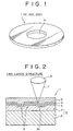
- Fig. 1 shows a preferred embodiment of a disk-like information recording medium of the present invention.
- a disk-like information recording medium 1 has a center hole H.
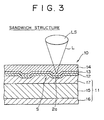
- Figs. 2 and 3 show sectional structure examples of the disk-like information recording medium 1 shown in Fig. 1.
- the disk-like information recording medium shown in Fig. 2 has a two-layer structure
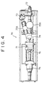
- the disk-like information recording medium shown in Fig. 3 has a sandwich structure of three layers.
- disk-like information recording media for example, optical information recording media for recording various kinds of information such as audio information or video information, various optical information recording media for performing recording or reproducing by light irradiation.
- disk-like information recording media there are known a compact disk (CD: trade name), a rewritable magneto-optical disk, a phase change disk, and the like.
- CD compact disk
- rewritable magneto-optical disk a phase change disk, and the like.
- an information recording layer of the disk-like information recording medium of these types it is required to form rows of patterns of fine irregularities such as prepits or grooves for recording data information, tracking servo signals, and the like.
- the disk-like information recording medium 1 of a type including a substrate of the two-layer structure shown in Fig. 2 is manufactured by laminating a light transmission layer 5, a recording layer 4, and a light reflection layer 3 on a substrate 2 of the two-layer structure.
- the substrate 2 is formed by laminating a surface layer (also called a skin layer) 7 to a core layer 6.
- the thickness of the core layer 6 is larger than that of the surface layer 7.
- Prepits or grooves are formed in one-sided plane of the surface layer 7.
- the light reflection layer 3, recording layer 4 and light transmission layer 5 are laminated on the surface layer 7.
- a laser beam L is made incident on the information recording medium 1 from the light transmission layer 5 side, to read an information signal or record an information signal from or on the information recording medium 1.
- the laser beam L introduced from a lens LS passes through the light transmission layer 5 and the recording layer 4, being reflected from the light reflection layer 5, and is returned to the lens LS side.
- the disk-like information recording medium 10 having the sandwich structure shown in Fig. 3 is formed by laminating a light transmission layer 14, a recording layer 13, and a light reflection layer 12 on a substrate 11 of the sandwich structure having three layers.
- Skin layers 16 and 17 are laminated on both surfaces of a core layer 15 of the substrate 11.
- the thickness of the core layer 15 is larger than that of each of the surface layers 16 and 17.
- Irregularities such as prepits or grooves are formed in one-sided plane of the surface layer 17.
- the light reflection layer 12, recording layer 13, and light transmission layer 14 are laminated on the surface layer 17.
- a laser beam L introduced from a lens LS passes through the light transmission layer 14 and the recording layer 13 is made incident on the light reflection layer 12, and the laser L reflected from the light reflection layer 12 is returned to the lens LS side.
- the core layer 6 of the substrate 2 integrally holds the surface layer 7
- the core layer 15 of the substrate 11 integrally holds the surface layers 16 and 17.
- Each of the core layers 6 and 15 is made from a resin; while each of the surface layers 7, 16 and 17 is made from a resin having a fluidity larger than that of the core layer at the same temperature environment.
- the light transmission layer is made from, for example a photo-curing resin, preferably, an ultraviolet-curing resin or optical transparent resin sheet.
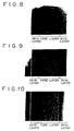
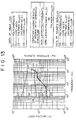
- a molding machine for molding the substrate 2 shown in Fig. 2 or the substrate 11 shown in Fig. 3 will be described with reference to Figs. 4 and 5.
- Figs. 4 and 5 show a molding machine 70.
- the molding machine 70 has a mold unit 71, an injection unit 72, and another injection unit 73.
- the injection path of the injection unit 72 is joined to that of the injection unit 73 at a nozzle 74.
- a hopper 72A is disposed on the midway of the injection unit 72, and a hopper 73A is disposed on the midway of the injection unit 73.
- the mold unit 71 faces to a nozzle 74 and has a fixed mold 71A and a movable mold 71B shown in Fig. 6.
- the movable mold 71B can be held at a specific position with respect to the fixed mold 71A by operating a piston 76 through a clamping cylinder 75.
- Fig. 5 shows the nozzle 74 shown in Fig. 4 and its neighborhood. As shown in Fig. 5, the injection paths of the injection units 72 and 73 are joined to each other at the nozzle 74.
- a resin for forming the surface layer (skin layer) 7 shown in Fig. 2 is fed in the hopper 72A shown in Fig. 4, and a resin for forming the core layer 6 shown in Fig. 2 is fed in the hopper 73A shown in Fig. 4.
- Fig. 6 shows the fixed mold 71A and the movable mold 71B of the mold unit 71 shown in Fig. 4.
- the resins are injected from the injection units 72 and 73 into a cavity between the fixed mold 71A and the movable mold 71B through a spool 77, to almost simultaneously mold the core layer 6 and the surface layer 7.
- a portion for forming prepits or grooves 78 is disposed on the mold 71A to form the pits or grooves 78 on the surface layer 7 simultaneously with molding of the core layer 6 and the surface layer 7.
- the mold 71 shown in Fig. 7 includes a fixed mold 71C and a movable mold 71D.
- prepits or grooves 78 are formed on the surface layer 17 side.
- the prepits or grooves 78 correspond to irregularities shown in Fig. 3.
- the irregularities such as the prepits or grooves 78 are already formed on the substrate composed of the core layer and surface layer laminated to each other shown in Fig. 6 or 7. And, the light transmission layer, recording layer, and light reflection layer shown in Fig. 2 or 3 are sequentially formed on the substrate.
- the above flexural modulus for single body is obtained by a measurement method specified under the standard of ASTM D790, and the value in the parenthesis is the result of measuring a sample cut off from an actual molded disk by a laboratory vibration lead method, and since there is no significant difference therebetween, the following data are expressed in results obtained by the vibration lead method.
- the substrate 11 with the sandwich structure shown in Fig. 3 was molded by using each of the above materials A-1 and A-2 for the skin layer A and each of the above materials B-1, B-2 and B-3 for the core layer B.
- the substrate 11 was molded by two different material simultaneously molding method using the molding machine 70 shown in Figs. 4 and 5, wherein the material for the skin layer was fed into the injection unit 72 and the material for the core layer was fed into the injection unit 73.
- Figs. 8 to 10 show sectional structure examples of the disk-like information recording medium of the sandwich structure thus obtained, wherein Fig. 8 shows the sectional state of an outermost peripheral portion of the disk-like information recording medium; Fig. 9 shows the sectional state of a central portion of the disk-like information recording medium; and Fig. 10 shows the sectional state of an innermost peripheral portion of the disk-like information recording medium.
- the material B-2 (polycarbonate + powder of mica) was used as the material for forming the core layer.
- the thickness of each skin layer of the sandwich structure was 0.3 mm.
- a strip-shaped sample having a width of 5 mm, a thickness of 1.2 mm and a length of 80 mm cut from each disk-like substrate thus obtained was measured in terms of flexural modulus by the vibration lead method. The results are as follows:
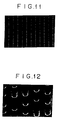
- Figs. 11 and 12 Examples of the surface characteristic of the surface layer thus obtained are shown in Figs. 11 and 12.
- Fig. 11 shows the example of transfer of grooves in the substrate of the disk-like information recording medium molded by sandwich molding. As is apparent from this figure, the influence of the filler does not appear on the surface of the surface layer.
- Fig. 12 shows the example of transfer of pits in the substrate of the disk-like information recording medium molded by sandwich molding.
- the vibration characteristic of the medium was improved by increasing an inner loss in a core layer.
- a sample having a width of 5 mm, a thickness of 1.5 mm and a length of 80 mm cut from a disk with the sandwich structure was measured in terms of inner loss and stiffness (Young's modulus) by the vibration lead method.
- a sample having a width of 5 mm, a thickness of 1.5 mm and a length of 80 mm cut from a disk with the sandwich structure molded under the same condition as that described above in the previous example was measured in terms of inner loss and stiffness (Young's modulus) by the vibration lead method.
- Fig. 13 shows results of measuring a loss factor ⁇ indicating the inner loss of vibration and a Young's modulus (Pa) indicating the stiffness for the substrate 11 with the sandwich structure in which polycarbonate is used for the surface layer (skin layer) and each of the polymer alloy B) and the filler mixed polycarbonate A) is used for the core layer.
- a loss factor ⁇ indicating the inner loss of vibration
- Pa Young's modulus
- a solid line D3 shows the inner loss of the substrate 11 in which the incompatible polymer alloy B) is used for the core layer
- a solid line D4 shows the inner loss of the substrate 11 in which the filler mixed polycarbonate A) is used for the core layer
- a solid line D2 shows the inner loss of the substrate 11 in which polycarbonate added with 20% of mica for improving only the stiffness is used for the core layer
- a solid line D1 shows the inner loss of the substrate 11 in which polycarbonate is used for the core layer.
- a broken line D7 shows the Young's modulus of the substrate 11 in which the incompatible polymer alloy B) is used for the core layer
- a broken line D8 shows the Young's modulus of the substrate 11 in which the filler mixed polycarbonate A) is used for the core layer
- a broken line D6 shows the Young's modulus of the substrate 11 in which polycarbonate added with 20% of mica for improving only the stiffness is used for the core layer
- a broken line D5 shows the Young's modulus of the substrate 11 in which polycarbonate is used for the core layer.
- the substrate in which the incompatible polymer alloy A) is used for the core layer shown by the solid line D3 and the broken line D7, is most preferable in consideration of both the inner loss of vibration and Young's modulus (stiffness).
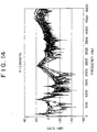
- the inner loss (dB) of an inventive disk prepared by using the substrate including the core layer made from the polymer alloy is plotted for each frequency as shown in Fig. 15 and is compared with that of a related art polycarbonate disk shown in Fig. 14.
- the values for the composite disk with the sandwich structure are of course lower than those for the single substrate; however, the inner loss of the composite disk is larger than that of the related art disk, and the resonance characteristic, obtained by oscillating the disk, of the inventive disk shown in Fig. 15 is significantly improved as compared with the related art disk shown in Fig. 14.
- the three-layer structure of the inventive disk was the perfect sandwich structure in which the thickness of each skin layer was 0.3 mm and the thickness of the core layer was 0.6 mm.
- the resin for the skin layer was injected in short-shot in the same manner as described above.
- the injected amount of the resin for the skin layer was about 40% on the basis of the total weight of the disk.
- the resin for the core layer was injected within a period of 0.02-0.5 sec while the skin layer was not solidified, to obtain a sandwich structure.
- the thickness of each skin layer of the sandwich structure was 0.3 mm.
- the weight of a disk with a sandwich structure thus obtained was reduced by 40% or more as compared with the related art polycarbonate disk.
- the present invention provides a flat disk (information recording medium) exhibiting a stiffness larger than that of a related art disk, preventing occurrence of resonance, and achieving a high transfer characteristic of irregularities in combination with excellent mechanical properties, which characteristics have been not obtained using only a single resin or single composite material.
- the inventive disk can significantly keep its flatness against the above factors by interposing a core layer having a high stiffness.
- the intermediate layer or core layer is made from a resin having a high damping characteristic capable of suppressing resonance due to plane runout caused upon rotation of the medium, it is possible to suppress occurrence of resonance even if the medium is rotated at a high speed.
- the intermediate layer is made from a polymer or a filler mixed composite resin capable of improving the damping characteristic
- characteristics having not been compatible with each other by use of a single material can be compatible with each other.
- a material having plate-like shapes having a high aspect ratio may be added as a filler for increasing the stiffness so as to withstand stress deformation to the intermediate layer or core layer for enhancing its stiffness.
- the aspect ratio is a ratio of the length to the diameter of a filler, and the stiffness of a resin is dependent on the aspect ratio of a filler added to the resin.
- a resin to which a filler having a small aspect ratio, for example, a filler having spherical shapes is added in a specific amount is lower in stiffness than the same resin to which a filler having a high aspect ratio, for example, a filler having plate-like shapes is added in the same amount.
- a filler having a high aspect ratio there are known a filler having plate-like shapes and a filler in the form of fibers.
- the filler in the form of fibers is undesirable because it has a high anisotropy.
- the contraction ratio in the peripheral direction is made different from that in the radial direction, to inevitably cause propeller-shaped deformation of the substrate.
- Examples of the fillers having a high aspect ratio are as follows: Plate-like glass mica talc glass fiber (MF) average length(L) 40 40 2-3 25 average diameter(D) 5 0.5-0.8 0.2-0.3 9 L/D 6-9 50-80 6-9 2-3
- L/D is an aspect ratio
- L is an average length of a filler
- D is a diameter of the filler
- MF is the abbreviation for milled fibers which are obtained by finely cutting fibers.
- an information recording medium whose weight is reduced by using the intermediate layer or core layer made from a resin to which a filler such as a foam is added, it is possible to reduce a load applied to a spindle upon rotation of the medium.
Applications Claiming Priority (2)
| Application Number | Priority Date | Filing Date | Title |
|---|---|---|---|
| JP17305198 | 1998-06-19 | ||
| JP17305198A JP4026234B2 (ja) | 1998-06-19 | 1998-06-19 | 情報記録媒体 |
Publications (3)
| Publication Number | Publication Date |
|---|---|
| EP0965985A2 true EP0965985A2 (fr) | 1999-12-22 |
| EP0965985A3 EP0965985A3 (fr) | 2000-01-26 |
| EP0965985B1 EP0965985B1 (fr) | 2004-01-14 |
Family
ID=15953315
Family Applications (1)
| Application Number | Title | Priority Date | Filing Date |
|---|---|---|---|
| EP99111682A Expired - Lifetime EP0965985B1 (fr) | 1998-06-19 | 1999-06-16 | Milieu d'enregistrement d'information |
Country Status (8)
| Country | Link |
|---|---|
| US (1) | US6201783B1 (fr) |
| EP (1) | EP0965985B1 (fr) |
| JP (1) | JP4026234B2 (fr) |
| KR (1) | KR100697753B1 (fr) |
| CN (1) | CN1135542C (fr) |
| DE (1) | DE69914133T2 (fr) |
| MY (1) | MY124607A (fr) |
| SG (1) | SG97793A1 (fr) |
Cited By (4)
| Publication number | Priority date | Publication date | Assignee | Title |
|---|---|---|---|---|
| WO2001059781A1 (fr) * | 2000-02-10 | 2001-08-16 | Sony Corporation | Support d'enregistrement du type disque et procede de production associe |
| EP1130587A2 (fr) * | 2000-03-03 | 2001-09-05 | Sony Corporation | Medium d' enregistrement optique |
| SG91933A1 (en) * | 2000-07-19 | 2002-10-15 | Sony Corp | Method of production of multilater optical recording medium |
| WO2003005354A1 (fr) * | 2001-07-02 | 2003-01-16 | General Electric Company | Polymeres monolithiques amortisseurs de vibrations |
Families Citing this family (8)
| Publication number | Priority date | Publication date | Assignee | Title |
|---|---|---|---|---|
| WO2003017266A1 (fr) * | 2001-08-10 | 2003-02-27 | Tdk Corporation | Support d'enregistrement optique |
| JP2003059097A (ja) * | 2001-08-10 | 2003-02-28 | Tdk Corp | 光記録媒体 |
| WO2003025926A1 (fr) * | 2001-09-18 | 2003-03-27 | Tdk Corporation | Procede d'inspection de support d'enregistrement optique |
| JP2004013947A (ja) * | 2002-06-04 | 2004-01-15 | Victor Co Of Japan Ltd | 情報記録担体、再生装置、記録装置、記録再生装置、再生方法、記録方法及び記録再生方法 |
| US7407698B2 (en) * | 2003-05-07 | 2008-08-05 | Ricoh Company, Ltd. | Flexible optical disk |
| US7366081B2 (en) * | 2004-11-10 | 2008-04-29 | Tdk Corporation | Information recording medium |
| JP5284723B2 (ja) * | 2007-08-24 | 2013-09-11 | 三菱化学メディア株式会社 | 光記録媒体背面層用放射線硬化性組成物、その硬化物、及びそれを用いた光記録媒体 |
| EP2051251A1 (fr) * | 2007-10-19 | 2009-04-22 | Bayer MaterialScience AG | Support d'enregistrement haute densité en forme de disque |
Citations (9)
| Publication number | Priority date | Publication date | Assignee | Title |
|---|---|---|---|---|
| JPS59177741A (ja) * | 1983-03-26 | 1984-10-08 | Pioneer Electronic Corp | デイスク及びその製造方法 |
| GB2145657A (en) * | 1983-08-15 | 1985-04-03 | Mitsui Toatsu Chemicals | Thermoplastic sheet, or film production process thereof |
| US4622261A (en) * | 1984-04-16 | 1986-11-11 | Fuji Photo Film Co., Ltd. | Laser recording material |
| EP0227981A2 (fr) * | 1985-12-09 | 1987-07-08 | Hitachi Maxell Ltd. | Procédé de fabrication d'un milieu d'enregistrement optique |
| US4893297A (en) * | 1968-06-06 | 1990-01-09 | Discovision Associates | Disc-shaped member |
| JPH04243034A (ja) * | 1991-01-18 | 1992-08-31 | Tdk Corp | 光記録媒体 |
| EP0509671A1 (fr) * | 1991-04-02 | 1992-10-21 | Kuraray Co., Ltd. | Milieu d'enregistrement d'information optique |
| JPH0714206A (ja) * | 1993-06-23 | 1995-01-17 | Ricoh Co Ltd | 情報記録媒体 |
| US5538774A (en) * | 1994-07-29 | 1996-07-23 | Minnesota Mining And Manufacturing Company | Internally damped rotatable storage article |
Family Cites Families (5)
| Publication number | Priority date | Publication date | Assignee | Title |
|---|---|---|---|---|
| US5234792A (en) * | 1988-11-09 | 1993-08-10 | Hitachi Maxell, Ltd. | Optical data recording medium and manufacturing method thereof |
| DE69030845T2 (de) * | 1989-01-11 | 1997-11-20 | Seiko Epson Corp | Optische platte und verfahren zur herstellung |
| US5225317A (en) * | 1989-10-31 | 1993-07-06 | Pioneer Electronic Corporation | Optical information recording medium |
| JPH09320109A (ja) * | 1996-05-30 | 1997-12-12 | Sony Corp | 光ディスク |
| JPH10154351A (ja) * | 1996-09-27 | 1998-06-09 | Sony Corp | 光学記録媒体とその製造方法 |
-
1998
- 1998-06-19 JP JP17305198A patent/JP4026234B2/ja not_active Expired - Fee Related
-
1999
- 1999-06-03 US US09/325,460 patent/US6201783B1/en not_active Expired - Fee Related
- 1999-06-14 SG SG9902913A patent/SG97793A1/en unknown
- 1999-06-16 DE DE69914133T patent/DE69914133T2/de not_active Expired - Fee Related
- 1999-06-16 EP EP99111682A patent/EP0965985B1/fr not_active Expired - Lifetime
- 1999-06-17 MY MYPI99002509A patent/MY124607A/en unknown
- 1999-06-18 CN CNB991086821A patent/CN1135542C/zh not_active Expired - Fee Related
- 1999-06-18 KR KR1019990022828A patent/KR100697753B1/ko not_active IP Right Cessation
Patent Citations (9)
| Publication number | Priority date | Publication date | Assignee | Title |
|---|---|---|---|---|
| US4893297A (en) * | 1968-06-06 | 1990-01-09 | Discovision Associates | Disc-shaped member |
| JPS59177741A (ja) * | 1983-03-26 | 1984-10-08 | Pioneer Electronic Corp | デイスク及びその製造方法 |
| GB2145657A (en) * | 1983-08-15 | 1985-04-03 | Mitsui Toatsu Chemicals | Thermoplastic sheet, or film production process thereof |
| US4622261A (en) * | 1984-04-16 | 1986-11-11 | Fuji Photo Film Co., Ltd. | Laser recording material |
| EP0227981A2 (fr) * | 1985-12-09 | 1987-07-08 | Hitachi Maxell Ltd. | Procédé de fabrication d'un milieu d'enregistrement optique |
| JPH04243034A (ja) * | 1991-01-18 | 1992-08-31 | Tdk Corp | 光記録媒体 |
| EP0509671A1 (fr) * | 1991-04-02 | 1992-10-21 | Kuraray Co., Ltd. | Milieu d'enregistrement d'information optique |
| JPH0714206A (ja) * | 1993-06-23 | 1995-01-17 | Ricoh Co Ltd | 情報記録媒体 |
| US5538774A (en) * | 1994-07-29 | 1996-07-23 | Minnesota Mining And Manufacturing Company | Internally damped rotatable storage article |
Non-Patent Citations (2)
| Title |
|---|
| PATENT ABSTRACTS OF JAPAN vol. 017, no. 016 (P-1468), 12 January 1993 (1993-01-12) -& JP 04 243034 A (TDK CORP), 31 August 1992 (1992-08-31) * |
| PATENT ABSTRACTS OF JAPAN vol. 1995, no. 04, 31 May 1995 (1995-05-31) -& JP 07 014206 A (RICOH CO LTD), 17 January 1995 (1995-01-17) * |
Cited By (8)
| Publication number | Priority date | Publication date | Assignee | Title |
|---|---|---|---|---|
| WO2001059781A1 (fr) * | 2000-02-10 | 2001-08-16 | Sony Corporation | Support d'enregistrement du type disque et procede de production associe |
| US6703100B2 (en) | 2000-02-10 | 2004-03-09 | Sony Corporation | Disk-like recording medium and method for producing the same |
| EP1130587A2 (fr) * | 2000-03-03 | 2001-09-05 | Sony Corporation | Medium d' enregistrement optique |
| EP1130587A3 (fr) * | 2000-03-03 | 2002-05-15 | Sony Corporation | Medium d' enregistrement optique |
| US6908655B2 (en) | 2000-03-03 | 2005-06-21 | Sony Corporation | Optical recording medium |
| SG91933A1 (en) * | 2000-07-19 | 2002-10-15 | Sony Corp | Method of production of multilater optical recording medium |
| WO2003005354A1 (fr) * | 2001-07-02 | 2003-01-16 | General Electric Company | Polymeres monolithiques amortisseurs de vibrations |
| KR100892464B1 (ko) * | 2001-07-02 | 2009-04-10 | 사빅 이노베이티브 플라스틱스 아이피 비.브이. | 진동 감쇠 단일체 중합체 |
Also Published As
| Publication number | Publication date |
|---|---|
| SG97793A1 (en) | 2003-08-20 |
| JP2000011449A (ja) | 2000-01-14 |
| EP0965985A3 (fr) | 2000-01-26 |
| DE69914133D1 (de) | 2004-02-19 |
| KR20000006267A (ko) | 2000-01-25 |
| CN1135542C (zh) | 2004-01-21 |
| CN1240292A (zh) | 2000-01-05 |
| JP4026234B2 (ja) | 2007-12-26 |
| KR100697753B1 (ko) | 2007-03-21 |
| EP0965985B1 (fr) | 2004-01-14 |
| US6201783B1 (en) | 2001-03-13 |
| MY124607A (en) | 2006-06-30 |
| DE69914133T2 (de) | 2004-11-11 |
Similar Documents
| Publication | Publication Date | Title |
|---|---|---|
| US6221455B1 (en) | Multi-layer optical disc and recording/reproducing apparatus | |
| US5989670A (en) | Multilayer optical disk | |
| EP0965985B1 (fr) | Milieu d'enregistrement d'information | |
| JP2680591B2 (ja) | 光メモリ素子の製造方法 | |
| US5987003A (en) | Coated disk substrate having a small thickness region | |
| JP2001250267A (ja) | 光記録媒体 | |
| JPH0568778B2 (fr) | ||
| US6875489B2 (en) | Optical recording medium | |
| EP0474050B1 (fr) | Disque magnéto-optique | |
| US6703100B2 (en) | Disk-like recording medium and method for producing the same | |
| US6636476B1 (en) | Optical recording medium with a substrate of two different resin layers | |
| JP2001189034A (ja) | 光記録媒体及びその製造方法 | |
| KR100587322B1 (ko) | 고강성 광 디스크의 제조 방법 | |
| US8137782B2 (en) | Optical media manufactured with low-grade materials | |
| KR100434274B1 (ko) | 고밀도 광디스크 및 그 제조방법 | |
| JP4326047B2 (ja) | 情報記録媒体 | |
| JPH07225972A (ja) | 光ディスク | |
| JP2000235734A (ja) | 光記録媒体及びその製造方法 | |
| JPH07262619A (ja) | 光学的情報記録媒体 | |
| JPH09320109A (ja) | 光ディスク | |
| KR20000049292A (ko) | 광기록 매체 및 그 제조방법 | |
| WO1994028545A1 (fr) | Substrat pour disque optique et disque optique l'utilisant | |
| KR20050025119A (ko) | 광학 기록 매체 | |
| JP2001155384A (ja) | 情報記録ディスク | |
| JPH1040582A (ja) | 光ディスク |
Legal Events
| Date | Code | Title | Description |
|---|---|---|---|
| PUAI | Public reference made under article 153(3) epc to a published international application that has entered the european phase |
Free format text: ORIGINAL CODE: 0009012 |
|
| PUAL | Search report despatched |
Free format text: ORIGINAL CODE: 0009013 |
|
| AK | Designated contracting states |
Kind code of ref document: A2 Designated state(s): DE FR NL |
|
| AX | Request for extension of the european patent |
Free format text: AL;LT;LV;MK;RO;SI |
|
| AK | Designated contracting states |
Kind code of ref document: A3 Designated state(s): AT BE CH CY DE DK ES FI FR GB GR IE IT LI LU MC NL PT SE |
|
| AX | Request for extension of the european patent |
Free format text: AL;LT;LV;MK;RO;SI |
|
| 17P | Request for examination filed |
Effective date: 20000726 |
|
| AKX | Designation fees paid |
Free format text: DE FR NL |
|
| 17Q | First examination report despatched |
Effective date: 20010822 |
|
| GRAP | Despatch of communication of intention to grant a patent |
Free format text: ORIGINAL CODE: EPIDOSNIGR1 |
|
| GRAS | Grant fee paid |
Free format text: ORIGINAL CODE: EPIDOSNIGR3 |
|
| GRAA | (expected) grant |
Free format text: ORIGINAL CODE: 0009210 |
|
| AK | Designated contracting states |
Kind code of ref document: B1 Designated state(s): DE FR NL |
|
| REF | Corresponds to: |
Ref document number: 69914133 Country of ref document: DE Date of ref document: 20040219 Kind code of ref document: P |
|
| ET | Fr: translation filed | ||
| PLBE | No opposition filed within time limit |
Free format text: ORIGINAL CODE: 0009261 |
|
| STAA | Information on the status of an ep patent application or granted ep patent |
Free format text: STATUS: NO OPPOSITION FILED WITHIN TIME LIMIT |
|
| 26N | No opposition filed |
Effective date: 20041015 |
|
| PGFP | Annual fee paid to national office [announced via postgrant information from national office to epo] |
Ref country code: NL Payment date: 20090603 Year of fee payment: 11 |
|
| PGFP | Annual fee paid to national office [announced via postgrant information from national office to epo] |
Ref country code: DE Payment date: 20090615 Year of fee payment: 11 |
|
| REG | Reference to a national code |
Ref country code: NL Ref legal event code: V1 Effective date: 20110101 |
|
| REG | Reference to a national code |
Ref country code: FR Ref legal event code: ST Effective date: 20110228 |
|
| PG25 | Lapsed in a contracting state [announced via postgrant information from national office to epo] |
Ref country code: DE Free format text: LAPSE BECAUSE OF NON-PAYMENT OF DUE FEES Effective date: 20110101 |
|
| PG25 | Lapsed in a contracting state [announced via postgrant information from national office to epo] |
Ref country code: FR Free format text: LAPSE BECAUSE OF NON-PAYMENT OF DUE FEES Effective date: 20100630 Ref country code: NL Free format text: LAPSE BECAUSE OF NON-PAYMENT OF DUE FEES Effective date: 20110101 |
|
| PGFP | Annual fee paid to national office [announced via postgrant information from national office to epo] |
Ref country code: FR Payment date: 20090611 Year of fee payment: 11 |