EP0964480B1 - Elément de connecteur électrique - Google Patents
Elément de connecteur électrique Download PDFInfo
- Publication number
- EP0964480B1 EP0964480B1 EP99110539A EP99110539A EP0964480B1 EP 0964480 B1 EP0964480 B1 EP 0964480B1 EP 99110539 A EP99110539 A EP 99110539A EP 99110539 A EP99110539 A EP 99110539A EP 0964480 B1 EP0964480 B1 EP 0964480B1
- Authority
- EP
- European Patent Office
- Prior art keywords
- segments
- carrier body
- additional member
- contacts
- plug connector
- Prior art date
- Legal status (The legal status is an assumption and is not a legal conclusion. Google has not performed a legal analysis and makes no representation as to the accuracy of the status listed.)
- Expired - Lifetime
Links
- 239000011810 insulating material Substances 0.000 claims description 6
- 238000003780 insertion Methods 0.000 description 8
- 230000037431 insertion Effects 0.000 description 8
- 230000015572 biosynthetic process Effects 0.000 description 7
- 238000005755 formation reaction Methods 0.000 description 7
- 230000000295 complement effect Effects 0.000 description 4
- 238000004519 manufacturing process Methods 0.000 description 2
- 230000002411 adverse Effects 0.000 description 1
- 238000005253 cladding Methods 0.000 description 1
- 230000000694 effects Effects 0.000 description 1
- 238000005516 engineering process Methods 0.000 description 1
- 238000009434 installation Methods 0.000 description 1
- 238000002955 isolation Methods 0.000 description 1
- 238000000034 method Methods 0.000 description 1
- 238000000465 moulding Methods 0.000 description 1
- 230000005405 multipole Effects 0.000 description 1
- 230000008054 signal transmission Effects 0.000 description 1
Images


Classifications
-
- H—ELECTRICITY
- H01—ELECTRIC ELEMENTS
- H01R—ELECTRICALLY-CONDUCTIVE CONNECTIONS; STRUCTURAL ASSOCIATIONS OF A PLURALITY OF MUTUALLY-INSULATED ELECTRICAL CONNECTING ELEMENTS; COUPLING DEVICES; CURRENT COLLECTORS
- H01R13/00—Details of coupling devices of the kinds covered by groups H01R12/70 or H01R24/00 - H01R33/00
- H01R13/46—Bases; Cases
- H01R13/516—Means for holding or embracing insulating body, e.g. casing, hoods
- H01R13/518—Means for holding or embracing insulating body, e.g. casing, hoods for holding or embracing several coupling parts, e.g. frames
-
- H—ELECTRICITY
- H01—ELECTRIC ELEMENTS
- H01R—ELECTRICALLY-CONDUCTIVE CONNECTIONS; STRUCTURAL ASSOCIATIONS OF A PLURALITY OF MUTUALLY-INSULATED ELECTRICAL CONNECTING ELEMENTS; COUPLING DEVICES; CURRENT COLLECTORS
- H01R12/00—Structural associations of a plurality of mutually-insulated electrical connecting elements, specially adapted for printed circuits, e.g. printed circuit boards [PCB], flat or ribbon cables, or like generally planar structures, e.g. terminal strips, terminal blocks; Coupling devices specially adapted for printed circuits, flat or ribbon cables, or like generally planar structures; Terminals specially adapted for contact with, or insertion into, printed circuits, flat or ribbon cables, or like generally planar structures
- H01R12/70—Coupling devices
- H01R12/71—Coupling devices for rigid printing circuits or like structures
- H01R12/72—Coupling devices for rigid printing circuits or like structures coupling with the edge of the rigid printed circuits or like structures
- H01R12/722—Coupling devices for rigid printing circuits or like structures coupling with the edge of the rigid printed circuits or like structures coupling devices mounted on the edge of the printed circuits
- H01R12/724—Coupling devices for rigid printing circuits or like structures coupling with the edge of the rigid printed circuits or like structures coupling devices mounted on the edge of the printed circuits containing contact members forming a right angle
Definitions
- the invention relates to an electrical connector part with a Insulating existing carrier body inserted in the electrical contacts are and are held by means of an additional part.
- a connector part which is designed as a spring or male connector can be a complementary connector part to manufacture inserted a multi-pin connector.
- the side by side have segments inserted into the carrier body of the connector part on the side which is inserted into the carrier body, contacts in a spring strip as contact springs or a male connector as a contact blade trained and to make contact with the corresponding Contact blades or contact springs of the complementary Plug connection part are provided.
- On another side of the segments are connected to the respective contacts connected terminal ends, for example, connected to terminals of a circuit board can be.
- the connection ends can be at right angles to the direction of insertion be arranged of the connector.
- the segments with their contacts and terminal ends are in different Variations made.
- the Overmolded contacts which is relatively expensive.
- the segments are made in two parts, and the contacts become inserted between the two segment halves.
- this has the disadvantage that a total of significantly more items must be processed.
- the contacts can also be simply inserted into slices, which, however, adversely affects their tightness.
- EP-A-0 486 298 a multi-contact connector for Signal transmission known in the crosstalk for signal contacts and ground contacts alternated in segmental design in a carrier housing are arranged.
- German Patent Application 196 34 844 and German Patent 195 33 295 housing known, in which an inner housing can be used. It will be a lid or a cap used to set the inner housing in the actual housing.
- the object of the invention is an electrical connector part with a carrier body consisting of insulating material in the electrical Contacts are inserted and held by means of an additional part, form the effect that the connector part in segment technology can be performed, the segments in the connector part sure are held precisely and firmly, with a simpler and therefore more cost-effective Assembly.
- This object is achieved in that in the carrier body a plurality of contacts and terminal ends contained segments are inserted, and that the segments are fixed by means of an additional part of insulating material, wherein the additional part is provided with comb-like projections, between which the segments are arranged.
- Such an additional part causes a firm hold of the segments in the carrier body and has the advantage that it serves in addition to the isolation of the segments with each other and thus leads to an improvement in the undesirable in connectors required air and creepage distances in the connector.
- the terminal ends of the segments are perpendicular to the insertion direction the contacts connectable to an advantageous connector configuration to reach at the terminal ends of the segments perpendicular to the insertion direction of the connector part, e.g. in appropriate Protruding holes of a printed circuit board.
- This can be a connector part to save space in the longitudinal direction of the board.
- the segments and their contacts are reached. That's how it can be Additional part with a bearing surface on a first, facing away from the contacts Press the end surface of each segment and thus the segment with a second end surface opposite the first end surface Press on a stop of the carrier body, causing the Insertion depth of the segments is set in the carrier body.
- a fixation the segments transverse to the insertion is by rib-shaped Formations on the additional part possible, each in a corresponding recess intervene in the first termination area of a segment.
- the outer segments of the connector part may preferably held by a projection in the support surface of the additional part be in a corresponding paragraph of the first closure surface engages a segment.
- the additional part preferably resilient latching lugs, which engage in corresponding recesses engage the carrier body and thus enable a firm locking.
- a support wall in the carrier body with Ribs may be provided, wherein the ribs each have a recess, in which engages a corresponding molded nose of the additional part.
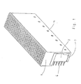
- Fig. 1 is a complete connector part 1 in the assembled state shown. It consists essentially of a rectangular carrier body 19 made of plastic with moldings for several side by side Segments 2, attached to which terminal ends 4 and 5 contacts are (see Fig. 2), by an additional part 3 in a defined position be held.
- the additional part 3 is designed so that it is not from the volume defined by the side walls of the carrier body 19 protrudes, i. the total volume of the connector part is through the additional part 3 is not enlarged.
- connector part 1 is a multi-pole spring connector with contacts, formed as contact springs and in formations 20 of the carrier body 19 are used.
- the invention can just as well Male connector with a bottom part with formations to be applied, in the segments are inserted with contact blades and in the one Insertion region of the contact elements surrounding collar is provided.
- FIG. 2 shows a single segment 2 of the plug connection part 1 from FIG. 1. It consists of insulating material, in which the terminal ends 4, with a Printed circuit board (not shown) to be connected, are embedded. The Terminal ends 4 are arranged at right angles to the contact springs 5. The Segment has a first, facing away from the contact springs 5 end surface 16 with a paragraph 18 and one of these first end face 16 opposite second end surface 11 in the first end surface 16 is located transversely to the longitudinal direction of a groove. 9
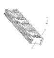
- elongated additional part 3 of Connector part 1 of Figure 1 has a comb-like structure, with some the emanating from a bearing surface 15 comb-like projections 24 laterally resilient locking lugs 12 have.
- On the long side everyone comb-like Anformung 24 is at the support surface 15 each have a nose 25th appropriate.
- ends of the comb-like Formations 24 are projections 7 and pin-shaped projections 27 provided.
- the support surface At the longitudinal ends of the additional part 3, the support surface each have a projection 17 and a rib-shaped Anformung. 8 on.
- Fig. 4 is an enlarged section of the support part 19 of the connector part 1 to see from Fig. 1.
- the strip recesses 20 are formed, each bounded by a stop 10.
- Sideways is one Provided support wall 21, formed on the ribs 23 with recesses 26 are.
- the support wall 21 has a plurality of recesses 14 on.
- the additional part 3 of insulating material is according to the view of FIG. 1 of Inserted below in the carrier body 19, in which previously the segments. 2 also used from below with upwardly facing contact springs 5 have been.
- the resilient locking lugs 12 of the additional part 3 snap it in the corresponding recesses 14 in the support wall 21 of the Carrier body 19 a.
- the comb-like projections 24 of the 3 additional part This ensures a secure locking of the segments 2.
- the projections 7 of the additional part 3 hold the finished assembled Plug connection part 1, the contact springs 5 of the segments 2 firmly in position.
- the bent contact springs 5 of the segments 2 come into engagement with the formations 7, whereby a secure contact with contact blades a complementary connector part (not shown) in the carrier body 19 is guaranteed.
- the additional part 3 presses with its support surface 15 on the first end surface 16 of each segment 2 and presses Thus, each segment 2 with its second end surface 11 on the associated Stop 10 of the carrier body 19. As a result, the insertion depth of Segments 2 defined exactly in the carrier body 19.
- each in the groove 9 of a segment 2 engages, the segments 2 of the additional part 3 in the transverse direction held relative to the insertion.
- the outermost segments of the spring connector part are respectively by the projection 17 in Fixed edge portion of the additional part 3, which in paragraph 18 of the corresponding Segments 2 comes to rest.
- a secure locking of the additional part 3 is achieved by the molded-on lugs 25 which are in the recesses 26 engage in the ribs 23 of the support wall 21 of the support body 19.
- the pin-shaped projections 27th provided on the additional part 3, which together with the contact springs 5 of Segments 2 protrude into the formations 20 of the support body 19.
- the connector part 1 described is designed so that in the removal of the additional part 3, the segments 2 are not held in the carrier body 19 become. This makes a quick and easy disassembly possible.
- means for the cohesion of the segments 2 with the carrier body 19 may be provided so that they hold together without the additional part 3 and thus form a preassemblable unit.
Claims (10)
- Elément de connecteur électrique à fiches avec un support (19) en matériau isolant dans lequel sont insérés des contacts électriques (5) maintenus par une pièce complémentaire (3), caractérisé en ce que plusieurs segments (2) pourvus de contacts (5) et d'extrémités de connexion (4) sont insérés dans le support (19) et en ce que les segments sont fixés grâce à cette pièce complémentaire (3) en matériau isolant, pourvue de saillies (24) en forme de dents de peigne entre lesquels sont disposés les segments (2).
- Elément de connecteur à fiches selon la revendication 1, caractérisé en ce que les extrémités de connexion (4) des segments (2) peuvent être connectées perpendiculairement à la direction d'enfichage des contacts (5).
- Elément de connecteur à fiches selon l'une des revendications 1 et 2, caractérisé en ce que la pièce complémentaire (3) comporte des prolongements (7) destinés à la fixation des contact (5) des segments (2) insérés dans le support (19).
- Elément de connecteur à fiches selon la revendication 3, caractérisé en ce que les contacts (5) des segments (2) sont coudés et coopèrent avec les prolongements (7) de la pièce complémentaire (3).
- Elément de connecteur à fiches selon l'une des revendications 2 à 4,
caractérisé en ce quele support (19) comporte une butée (10),les segments (2) présentent une première surface frontale (16) opposée aux contacts (5) et une seconde surface frontale (11) faisant face à ladite première surface frontale (16),la pièce complémentaire (3) comporte une surface de base (15) exerçant une pression sur la première surface frontale (16) d'un segment (2) de sorte que le segment (2) est appuyé par sa seconde surface frontale (11) sur la butée (10) du support (19). - Elément de connecteur à fiches selon l'une des revendications 2 à 5, caractérisé en ce que la pièce complémentaire (3) comporte des sailles (8) en forme de nervures qui s'engagent dans une encoche (9) correspondante dans la surface frontale (16) du segment (2) opposée aux contacts (5) afin de maintenir le segment (2) en direction d'enfichage.
- Elément de connecteur à fiches selon la revendication 5, caractérisé en ce que la surface d'appui (15) de la pièce complémentaire (3) est pourvue d'un épaulement (17) s'engageant dans un étagement (18) correspondant de la surface frontale supérieure (16) du segment extrême (2) afin de maintenir ce segment dans le support (19).
- Elément de connecteur à fiches selon l'une des revendications précédentes, caractérisé en ce que la pièce complémentaire (3) comporte des nez d'arrêt (12) élastiques s'engageant dans une ouverture d'encliquetage (14) dans le support (19) afin de bloquer la pièce complémentaire (3) sur le support (19).
- Elément de connecteur à fiches selon l'une des revendications précédentes, caractérisé en ce que le support (19) comprend une paroi d'appui (21) qui comporte des nervures (23) pourvues chacune d'un évidement (26) dans lequel s'engage le nez (25) correspondant de la pièce complémentaire (3).
- Elément de connecteur à fiches selon l'une des revendications précédentes, caractérisé en ce que le support (19) et les segments (2) sont assemblés uniquement par la pièce complémentaire (3).
Applications Claiming Priority (3)
| Application Number | Priority Date | Filing Date | Title |
|---|---|---|---|
| DE19825971A DE19825971C1 (de) | 1998-06-10 | 1998-06-10 | Elektrisches Steckverbindungsteil |
| DE19825971 | 1998-06-10 | ||
| US09/326,259 US6196853B1 (en) | 1998-06-10 | 1999-06-04 | Electric plug connector |
Publications (3)
| Publication Number | Publication Date |
|---|---|
| EP0964480A2 EP0964480A2 (fr) | 1999-12-15 |
| EP0964480A3 EP0964480A3 (fr) | 2002-03-13 |
| EP0964480B1 true EP0964480B1 (fr) | 2003-09-17 |
Family
ID=26046737
Family Applications (1)
| Application Number | Title | Priority Date | Filing Date |
|---|---|---|---|
| EP99110539A Expired - Lifetime EP0964480B1 (fr) | 1998-06-10 | 1999-06-01 | Elément de connecteur électrique |
Country Status (4)
| Country | Link |
|---|---|
| US (1) | US6196853B1 (fr) |
| EP (1) | EP0964480B1 (fr) |
| JP (1) | JP3117965B2 (fr) |
| DE (1) | DE19825971C1 (fr) |
Families Citing this family (22)
| Publication number | Priority date | Publication date | Assignee | Title |
|---|---|---|---|---|
| US6361366B1 (en) * | 1997-08-20 | 2002-03-26 | Fci Americas Technology, Inc. | High speed modular electrical connector and receptacle for use therein |
| DE20003951U1 (de) * | 2000-03-08 | 2001-07-12 | Bosch Gmbh Robert | Mehrpoliger elektrischer Steckverbinder |
| US6709298B2 (en) * | 2001-04-06 | 2004-03-23 | Litton Systems, Inc. | Insulator coring and contact configuration to prevent pin stubbing in the throat of tuning fork socket connector contacts |
| US6979215B2 (en) | 2001-11-28 | 2005-12-27 | Molex Incorporated | High-density connector assembly with flexural capabilities |
| US6743057B2 (en) * | 2002-03-27 | 2004-06-01 | Tyco Electronics Corporation | Electrical connector tie bar |
| US6764349B2 (en) * | 2002-03-29 | 2004-07-20 | Teradyne, Inc. | Matrix connector with integrated power contacts |
| US6638079B1 (en) * | 2002-05-21 | 2003-10-28 | Hon Hai Precision Ind. Co., Ltd. | Customizable electrical connector |
| JP3929931B2 (ja) * | 2003-05-13 | 2007-06-13 | 株式会社オートネットワーク技術研究所 | コネクタの圧入用治具 |
| US6884117B2 (en) * | 2003-08-29 | 2005-04-26 | Hon Hai Precision Ind. Co., Ltd. | Electrical connector having circuit board modules positioned between metal stiffener and a housing |
| US7976345B2 (en) * | 2005-12-15 | 2011-07-12 | Tyco Electronics Corporation | Electrical contact assembly and method of manufacturing thereof |
| DE202006016424U1 (de) * | 2006-10-20 | 2007-01-04 | Phoenix Contact Gmbh & Co. Kg | Elektrische Kontaktvorrichtung |
| CN107069274B (zh) | 2010-05-07 | 2020-08-18 | 安费诺有限公司 | 高性能线缆连接器 |
| US9831588B2 (en) | 2012-08-22 | 2017-11-28 | Amphenol Corporation | High-frequency electrical connector |
| CN106463859B (zh) | 2014-01-22 | 2019-05-17 | 安费诺有限公司 | 具有边缘至宽边过渡的超高速高密度电互连系统 |
| CN114552261A (zh) | 2015-07-07 | 2022-05-27 | 安费诺富加宜(亚洲)私人有限公司 | 电连接器 |
| CN112151987B (zh) | 2016-08-23 | 2022-12-30 | 安费诺有限公司 | 可配置为高性能的连接器 |
| CN208862209U (zh) | 2018-09-26 | 2019-05-14 | 安费诺东亚电子科技(深圳)有限公司 | 一种连接器及其应用的pcb板 |
| CN110620300A (zh) * | 2019-05-21 | 2019-12-27 | 中航光电科技股份有限公司 | 一种连接器固定件及连接器 |
| WO2021154718A1 (fr) | 2020-01-27 | 2021-08-05 | Fci Usa Llc | Connecteur orthogonal à accouplement direct à haute densité et à grande vitesse |
| CN115428275A (zh) | 2020-01-27 | 2022-12-02 | 富加宜(美国)有限责任公司 | 高速连接器 |
| CN215816516U (zh) | 2020-09-22 | 2022-02-11 | 安费诺商用电子产品(成都)有限公司 | 电连接器 |
| CN213636403U (zh) | 2020-09-25 | 2021-07-06 | 安费诺商用电子产品(成都)有限公司 | 电连接器 |
Family Cites Families (10)
| Publication number | Priority date | Publication date | Assignee | Title |
|---|---|---|---|---|
| ES2070283T3 (es) * | 1989-10-10 | 1995-06-01 | Whitaker Corp | Conectador a contraplano con impedancias adaptadas. |
| JP2739608B2 (ja) * | 1990-11-15 | 1998-04-15 | 日本エー・エム・ピー株式会社 | 信号伝送用マルチコンタクト型コネクタ |
| US5199886A (en) * | 1991-11-19 | 1993-04-06 | Amp Incorporated | Shrouded connector assembly |
| GB9205087D0 (en) * | 1992-03-09 | 1992-04-22 | Amp Holland | Sheilded back plane connector |
| DE19533295C1 (de) * | 1995-09-08 | 1997-04-10 | Siemens Ag | Hybrider Steckverbinder mit modularen elektrischen und Lichtwellenleiter-Steckverbindungen |
| US5716237A (en) * | 1996-06-21 | 1998-02-10 | Lucent Technologies Inc. | Electrical connector with crosstalk compensation |
| US6010373A (en) * | 1996-06-26 | 2000-01-04 | Robinson Nugent, Inc. | Electrical connector interlocking apparatus |
| DE19634844C2 (de) * | 1996-08-28 | 1998-10-15 | Siemens Ag | Steckverbinder mit verschließbarem Deckelteil |
| US5924899A (en) * | 1997-11-19 | 1999-07-20 | Berg Technology, Inc. | Modular connectors |
| US5961355A (en) * | 1997-12-17 | 1999-10-05 | Berg Technology, Inc. | High density interstitial connector system |
-
1998
- 1998-06-10 DE DE19825971A patent/DE19825971C1/de not_active Expired - Lifetime
-
1999
- 1999-06-01 EP EP99110539A patent/EP0964480B1/fr not_active Expired - Lifetime
- 1999-06-04 US US09/326,259 patent/US6196853B1/en not_active Expired - Lifetime
- 1999-06-07 JP JP15986899A patent/JP3117965B2/ja not_active Expired - Fee Related
Also Published As
| Publication number | Publication date |
|---|---|
| JP3117965B2 (ja) | 2000-12-18 |
| EP0964480A2 (fr) | 1999-12-15 |
| US6196853B1 (en) | 2001-03-06 |
| JP2000012173A (ja) | 2000-01-14 |
| EP0964480A3 (fr) | 2002-03-13 |
| DE19825971C1 (de) | 1999-11-11 |
Similar Documents
| Publication | Publication Date | Title |
|---|---|---|
| EP0964480B1 (fr) | Elément de connecteur électrique | |
| EP1801927B1 (fr) | Cadre support pour module de connecteur | |
| DE60027611T2 (de) | Kabelverbinder mit gesteuerter Impedanz | |
| DE3807645C2 (de) | Steckverbindungssystem für elektrische Leiter | |
| DE60221427T2 (de) | Gegossener elektrischer Verbinder | |
| DE3541772A1 (de) | Aufnahmeteil fuer elektrische steckverbinder | |
| DE102009022094A1 (de) | Stapelverbinder | |
| EP0766352B1 (fr) | Réglette de connexion ayant un débit de transmission élevé | |
| EP1429423B1 (fr) | Connecteur électrique à fiche ayant un boîtier et un contact à courant fort | |
| DE19939580A1 (de) | Elektrischer Steckverbinder | |
| DE10119695B4 (de) | Steckverbinder für elektronische Bauelemente | |
| DE1956095C3 (de) | Elektrischer Mehrfachsteckverbinder | |
| DE4017453C2 (fr) | ||
| WO2008110190A2 (fr) | Connecteur électrique comprenant un couvercle antipoussière | |
| DE3525297A1 (de) | Elektrische steckverbindung | |
| DE4425748C1 (de) | Elektrischer Steckverbinder | |
| DE4018978C2 (de) | Schiebeschalter | |
| EP0122373A2 (fr) | Connecteur électrique | |
| DE602004001350T2 (de) | Stecker für Bandkabel | |
| DE4332996C2 (de) | Steckverbinder zur Kontaktierung einer Leiterplatte | |
| EP3644460B1 (fr) | Système de rails conducteurs | |
| DE60107757T2 (de) | Leiterplattensteckverbinder | |
| EP1154521A1 (fr) | Connecteur et procédé de montage de connecteur | |
| EP1445840B1 (fr) | Connecteur Electrique | |
| DE19753843A1 (de) | Modulare Anordnung zur Potentialverteilung |
Legal Events
| Date | Code | Title | Description |
|---|---|---|---|
| PUAI | Public reference made under article 153(3) epc to a published international application that has entered the european phase |
Free format text: ORIGINAL CODE: 0009012 |
|
| AK | Designated contracting states |
Kind code of ref document: A2 Designated state(s): AT BE CH CY DE DK ES FI FR GB GR IE IT LI LU MC NL PT SE Kind code of ref document: A2 Designated state(s): DE FI FR GB IT SE |
|
| AX | Request for extension of the european patent |
Free format text: AL;LT;LV;MK;RO;SI |
|
| PUAL | Search report despatched |
Free format text: ORIGINAL CODE: 0009013 |
|
| AK | Designated contracting states |
Kind code of ref document: A3 Designated state(s): AT BE CH CY DE DK ES FI FR GB GR IE IT LI LU MC NL PT SE |
|
| AX | Request for extension of the european patent |
Free format text: AL;LT;LV;MK;RO;SI |
|
| 17P | Request for examination filed |
Effective date: 20020408 |
|
| 17Q | First examination report despatched |
Effective date: 20020614 |
|
| GRAH | Despatch of communication of intention to grant a patent |
Free format text: ORIGINAL CODE: EPIDOS IGRA |
|
| GRAH | Despatch of communication of intention to grant a patent |
Free format text: ORIGINAL CODE: EPIDOS IGRA |
|
| AKX | Designation fees paid |
Free format text: DE FI FR GB IT SE |
|
| GRAH | Despatch of communication of intention to grant a patent |
Free format text: ORIGINAL CODE: EPIDOS IGRA |
|
| RIC1 | Information provided on ipc code assigned before grant |
Ipc: 7H 01R 12/18 B Ipc: 7H 01R 13/518 A |
|
| GRAA | (expected) grant |
Free format text: ORIGINAL CODE: 0009210 |
|
| AK | Designated contracting states |
Kind code of ref document: B1 Designated state(s): DE FI FR GB IT SE |
|
| REG | Reference to a national code |
Ref country code: GB Ref legal event code: FG4D Free format text: NOT ENGLISH |
|
| REF | Corresponds to: |
Ref document number: 59906990 Country of ref document: DE Date of ref document: 20031023 Kind code of ref document: P |
|
| REG | Reference to a national code |
Ref country code: IE Ref legal event code: FG4D Free format text: GERMAN |
|
| RAP2 | Party data changed (patent owner data changed or rights of a patent transferred) |
Owner name: HARTING ELECTRONICS GMBH & CO. KG |
|
| REG | Reference to a national code |
Ref country code: SE Ref legal event code: TRGR |
|
| REG | Reference to a national code |
Ref country code: GB Ref legal event code: 732E |
|
| GBT | Gb: translation of ep patent filed (gb section 77(6)(a)/1977) |
Effective date: 20040123 |
|
| REG | Reference to a national code |
Ref country code: IE Ref legal event code: FD4D |
|
| ET | Fr: translation filed | ||
| PLBE | No opposition filed within time limit |
Free format text: ORIGINAL CODE: 0009261 |
|
| STAA | Information on the status of an ep patent application or granted ep patent |
Free format text: STATUS: NO OPPOSITION FILED WITHIN TIME LIMIT |
|
| 26N | No opposition filed |
Effective date: 20040618 |
|
| REG | Reference to a national code |
Ref country code: FR Ref legal event code: PLFP Year of fee payment: 18 |
|
| PGFP | Annual fee paid to national office [announced via postgrant information from national office to epo] |
Ref country code: FI Payment date: 20160609 Year of fee payment: 18 |
|
| REG | Reference to a national code |
Ref country code: FR Ref legal event code: PLFP Year of fee payment: 19 |
|
| PGFP | Annual fee paid to national office [announced via postgrant information from national office to epo] |
Ref country code: CH Payment date: 20170912 Year of fee payment: 10 |
|
| PG25 | Lapsed in a contracting state [announced via postgrant information from national office to epo] |
Ref country code: FI Free format text: LAPSE BECAUSE OF NON-PAYMENT OF DUE FEES Effective date: 20170601 |
|
| REG | Reference to a national code |
Ref country code: FR Ref legal event code: PLFP Year of fee payment: 20 |
|
| PGFP | Annual fee paid to national office [announced via postgrant information from national office to epo] |
Ref country code: FR Payment date: 20180628 Year of fee payment: 20 |
|
| PGFP | Annual fee paid to national office [announced via postgrant information from national office to epo] |
Ref country code: DE Payment date: 20180831 Year of fee payment: 20 Ref country code: GB Payment date: 20180629 Year of fee payment: 20 Ref country code: IT Payment date: 20180622 Year of fee payment: 20 |
|
| REG | Reference to a national code |
Ref country code: SE Ref legal event code: EUG |
|
| PG25 | Lapsed in a contracting state [announced via postgrant information from national office to epo] |
Ref country code: SE Free format text: LAPSE BECAUSE OF NON-PAYMENT OF DUE FEES Effective date: 20180602 |
|
| REG | Reference to a national code |
Ref country code: DE Ref legal event code: R071 Ref document number: 59906990 Country of ref document: DE |
|
| REG | Reference to a national code |
Ref country code: GB Ref legal event code: PE20 Expiry date: 20190531 |
|
| PG25 | Lapsed in a contracting state [announced via postgrant information from national office to epo] |
Ref country code: GB Free format text: LAPSE BECAUSE OF EXPIRATION OF PROTECTION Effective date: 20190531 |