EP0964480A2 - Elektrisches Steckverbindungsteil - Google Patents
Elektrisches Steckverbindungsteil Download PDFInfo
- Publication number
- EP0964480A2 EP0964480A2 EP99110539A EP99110539A EP0964480A2 EP 0964480 A2 EP0964480 A2 EP 0964480A2 EP 99110539 A EP99110539 A EP 99110539A EP 99110539 A EP99110539 A EP 99110539A EP 0964480 A2 EP0964480 A2 EP 0964480A2
- Authority
- EP
- European Patent Office
- Prior art keywords
- carrier body
- segments
- additional part
- contacts
- segment
- Prior art date
- Legal status (The legal status is an assumption and is not a legal conclusion. Google has not performed a legal analysis and makes no representation as to the accuracy of the status listed.)
- Granted
Links
Images


Classifications
-
- H—ELECTRICITY
- H01—ELECTRIC ELEMENTS
- H01R—ELECTRICALLY-CONDUCTIVE CONNECTIONS; STRUCTURAL ASSOCIATIONS OF A PLURALITY OF MUTUALLY-INSULATED ELECTRICAL CONNECTING ELEMENTS; COUPLING DEVICES; CURRENT COLLECTORS
- H01R13/00—Details of coupling devices of the kinds covered by groups H01R12/70 or H01R24/00 - H01R33/00
- H01R13/46—Bases; Cases
- H01R13/516—Means for holding or embracing insulating body, e.g. casing, hoods
- H01R13/518—Means for holding or embracing insulating body, e.g. casing, hoods for holding or embracing several coupling parts, e.g. frames
-
- H—ELECTRICITY
- H01—ELECTRIC ELEMENTS
- H01R—ELECTRICALLY-CONDUCTIVE CONNECTIONS; STRUCTURAL ASSOCIATIONS OF A PLURALITY OF MUTUALLY-INSULATED ELECTRICAL CONNECTING ELEMENTS; COUPLING DEVICES; CURRENT COLLECTORS
- H01R12/00—Structural associations of a plurality of mutually-insulated electrical connecting elements, specially adapted for printed circuits, e.g. printed circuit boards [PCB], flat or ribbon cables, or like generally planar structures, e.g. terminal strips, terminal blocks; Coupling devices specially adapted for printed circuits, flat or ribbon cables, or like generally planar structures; Terminals specially adapted for contact with, or insertion into, printed circuits, flat or ribbon cables, or like generally planar structures
- H01R12/70—Coupling devices
- H01R12/71—Coupling devices for rigid printing circuits or like structures
- H01R12/72—Coupling devices for rigid printing circuits or like structures coupling with the edge of the rigid printed circuits or like structures
- H01R12/722—Coupling devices for rigid printing circuits or like structures coupling with the edge of the rigid printed circuits or like structures coupling devices mounted on the edge of the printed circuits
- H01R12/724—Coupling devices for rigid printing circuits or like structures coupling with the edge of the rigid printed circuits or like structures coupling devices mounted on the edge of the printed circuits containing contact members forming a right angle
Definitions
- the invention relates to an electrical connector part, which has a carrier body made of insulating material and several inserted into the carrier body Contains segments with contacts and connection ends.
- a connector part which is designed as a spring or knife strip can be a complementary connector part for manufacturing a multi-pin connector.
- the side by side have segments used in the carrier body of the connector part on the side that is inserted into the carrier body, contacts on the with a female connector as contact springs or with a male connector as contact knife trained and to establish contact with the appropriate Contact knives or contact springs of the complementary Plug connector part are provided.
- connection ends connected to the respective contacts are formed, which are connected, for example, to connections on a printed circuit board can be.
- the connection ends can be perpendicular to the direction of insertion of the connector can be arranged.
- the segments with their contacts and connection ends are in different Variations made.
- the Injection molded contacts which is relatively expensive.
- the segments are made in two parts, and the contacts inserted between the two segment halves.
- the contacts can also simply be inserted into discs be, which however has an adverse effect on their tight fit.
- the object of the invention is an electrical connector part to create in segment technology, in which the segments in the connector part are safe, precise and permanently installed with simpler and therefore cheaper Assembly.
- an electrical plug-in connection part a carrier body made of insulating material and several in the carrier body contains inserted segments with contacts and connection ends, where a Additional part made of insulating material is provided, the segments in the carrier body fixed and provided with comb-like formations that between the segments are arranged.
- Such an additional part causes a firm Hold the segments in the carrier body and has the advantage that it is additional serves to isolate the segments from one another and thus to improve them with regard to the undesirable required with connectors Clearances and creepage distances in the connector leads.
- connection ends of the segments are preferably at right angles to the direction of insertion the contacts connectable to an advantageous connector configuration to achieve at the connecting ends of the segments perpendicular to the direction of insertion of the connector part e.g. in corresponding Holes of a PCB protrude. This allows a connector part space-saving in the longitudinal direction of the board.
- Various additional measures can improve fixation of the segments and their contacts can be reached.
- This can be about Additional part with a contact surface on a first, facing away from the contacts Press the end surface of each segment and thus the segment with a second end surface opposite the first end surface press on a stop of the carrier body, whereby the Insertion depth of the segments in the carrier body is determined.
- a fixation the segments transverse to their direction of insertion is rib-shaped Formations on the additional part possible, each in a corresponding recess engage in the first end face of a segment.
- the outer segments of the connector part can preferably held by a projection in the support surface of the additional part be in a corresponding paragraph of the first end area of a segment engages.
- the additional part preferably resilient locking lugs, which in corresponding locking recesses engage the carrier body and thus enable a firm locking.
- a support wall can also be provided in the carrier body Ribs may be provided, the ribs each having a recess, into which a corresponding molded nose of the additional part engages.
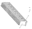
- Fig. 1 is a complete connector part 1 in the assembled state shown. It essentially consists of a rectangular support body 19 made of plastic with moldings for several used side by side Segments 2, to which connection ends 4 and contacts 5 are attached are (see Fig. 2) by an additional part 3 in a defined position be held.
- the additional part 3 is designed so that it is not from the volume defined by the side walls of the carrier body 19 protrudes, i.e. the total volume of the connector part is by the additional part 3 is not enlarged.
- the connector part shown in Fig. 1 1 is a multipole female connector with contacts, which are designed as contact springs and in the formations 20 of the carrier body 19 are used.
- the invention can also be applied to a Male connector with a bottom part with formations can be applied in the segments with contact blades are used and the one with the Mating area of the contact elements surrounding the collar is provided.
- FIG. 2 shows a single segment 2 of the connector part 1 from FIG. 1. It consists of insulating material into which the connection ends 4, which are connected to a PCB (not shown) to be connected, are embedded.
- the Terminal ends 4 are arranged at right angles to the contact springs 5.
- the Segment has a first end surface facing away from the contact springs 5 16 with a shoulder 18 and one of these first end surface 16 opposite second end surface 11. In the first end surface 16 there is a groove 9 transverse to its longitudinal direction.
- Recesses 20 are formed in the bar, which are each limited by a stop 10.
- the support wall 21 has a plurality of locking recesses 14 on.
- the additional part 3 made of insulating material is according to the view of FIG inserted at the bottom into the carrier body 19, in which the segments 2 also used from below with contact springs 5 pointing upwards have been.
- the resilient locking lugs 12 of the additional part 3 snap in the corresponding locking recesses 14 in the support wall 21 of the Carrier body 19 a.
- the projections 7 of the additional part 3 hold when fully assembled Connector part 1, the contact springs 5 of the segments 2 firmly in position.
- the bent contact springs 5 of the segments 2 come into engagement with the formations 7, with which a reliable contact with contact blades a complementary connector part (not shown) in the carrier body 19 is guaranteed.
- the additional part 3 presses with its contact surface 15 on the first end surface 16 of each segment 2 and presses thus each segment 2 with its second end face 11 on the associated Stop 10 of the carrier body 19. This is the insertion depth of the Segments 2 are precisely defined in the carrier body 19.
- each in the groove 9 of a segment 2 grabs the segments 2 of the additional part 3 in the transverse direction held in relation to the direction of insertion.
- the outermost segments of the spring connector part are each by the projection 17 in Border area of the additional part 3 recorded in paragraph 18 of the corresponding Segment 2 comes to rest.
- Secure locking of the additional part 3 is achieved by the molded lugs 25, which are in the recesses 26 engage in the ribs 23 of the support wall 21 of the carrier body 19.
- the pin-shaped projections 27 provided on the additional part 3, which together with the contact springs 5 of the Segments 2 protrude into the formations 20 of the carrier body 19.
- the connector part 1 described is designed so that the removal of the additional part 3, the segments 2 are not held in the carrier body 19 become. This makes disassembly quick and easy.
- can also be used for simplified assembly of the plug-in connection part 1 means for the cohesion of the segments 2 with the support body 19 may be provided so that they hold together without the additional part 3 and so form a preassembled unit.
Landscapes
- Coupling Device And Connection With Printed Circuit (AREA)
- Connector Housings Or Holding Contact Members (AREA)
- Details Of Connecting Devices For Male And Female Coupling (AREA)
Abstract
Description
- Figur 1
- eine perspektivische Ansicht eines elektrischen Steckverbindungsteils, das als Federleiste ausgebildet ist,
- Figur 2
- eine perspektivische Ansicht eines Segments, das bei dem in Fig. 1 gezeigten Steckverbindungsteil verwendet wird
- Figur 3
- eine perspektivische Ansicht eines Zusatzteils, das bei dem in Fig. 1 gezeigten Steckverbindungsteil verwendet wird
- Figur 3a
- in vergrößertem Maßstab einen Ausschnitt des Zusatzteils aus Figur 3, und
- Figur 4
- in vergrößertem Maßstab perspektivisch einen Ausschnitt eines Trägerkörpers, der bei dem in Fig. 1 gezeigten Steckverbindungsteil verwendet wird.
Claims (10)
- Elektrisches Steckverbindungsteil, das einen Trägerkörper (19) aus Isoliermaterial und mehrere in den Trägerkörper (19) eingesetzte Segmente (2) mit Kontakten (5) und Anschlußenden (4) enthält, wobei ein Zusatzteil (3) aus Isoliermaterial vorgesehen ist, das die Segmente (2) im Trägerkörper (19) fixiert und mit kammartigen Anformungen (24) versehen ist, die zwischen den Segmenten (2) angeordnet sind.
- Steckverbindungsteil nach Anspruch 1, dadurch gekennzeichnet,daß die Anschlußenden (4) der Segmente (2) rechtwinklig zur Einsteckrichtung der Kontakte (5) verbindbar sind.
- Steckverbindungsteil nach einem der Ansprüche 1 und 2, dadurch gekennzeichnet,daß das Zusatzteil (3) Anformungen (7) aufweist, die zur Fixierung der Kontakte (5) der in den Trägerkörper (19) eingesetzten Segmente (2) vorgesehen sind.
- Steckverbindungsteil nach Anspruch 3, dadurch gekennzeichnet,daß die Kontakte (5) der Segmente (2) abgekröpft sind und in Eingriff mit den Anformungen (7) des Zusatzteils (3) kommen.
- Steckverbindungsteil nach einem der Ansprüche 2 bis 4, dadurch gekennzeichnet,daß der Trägerkörper (19) einen Anschlag (10) umfaßt, daß die Segmente (2) mit einer den Kontakten (5) abgewandten ersten Abschlußfläche (16) und einer dieser ersten Abschlußfläche (16) gegenüberliegenden zweiten Abschlußfläche (11) ausgebildet sind unddaß das Zusatzteil (3) eine Auflagefläche (15) umfaßt, welche auf die erste Abschlußfläche (16) eines Segments (2) drückt und damit das Segment (2) mit der zweiten Abschlußfläche (11) auf den Anschlag (10) des Trägerkörpers (19) drückt.
- Steckverbindungsteil nach einem der Ansprüche 2 bis 5, dadurch gekennzeichnet,daß das Zusatzteil (3) rippenförmige Anformungen (8) aufweist, die jeweils in eine entsprechende Ausnehmung (9) einer den Kontakten (5) abgewandten ersten Abschlußfläche (16) eines Segments (2) eingreifen, um das Segment (2) quer zu seiner Einsteckrichtung zu fixieren.
- Steckverbindungsteil nach Anspruch 5, dadurch gekennzeichnet,daß die Auflagefläche (15) des Zusatzteils (3) einen Vorsprung (17) aufweist, der in einen entsprechenden Absatz (18) der oberen Abschlußfläche (16) eines äußeren Segments eingreift, um dieses Segment im Trägerkörper (19) festzuhalten.
- Steckverbindungsteil nach einem der vorhergehenden Ansprüche, dadurch gekennzeichnet,daß das Zusatzteil (3) federnde Rastnasen (12) aufweist, die jeweils in eine Rastausnehmung (14) des Trägerkörpers (19) zur festen Arretierung des Zusatzteils (3) an den Trägerkörper (19) eingreifen.
- Steckverbindungsteil nach einem der vorhergehenden Ansprüche, dadurch gekennzeichnet,daß der Trägerkörper (19) eine Stützwand (21) mit Rippen (23) umfaßt, wobei die Rippen (23) Aussparungen (26) aufweisen, in die entsprechende angeformte Nasen (25) des Zusatzteils (3) eingreifen.
- Steckverbindungsteil nach einem der vorhergehenden Ansprüche, dadurch gekennzeichnet,daß der Trägerkörper (19) und die Segmente (2) nur durch das Zusatzteil (3) zusammengehalten werden.
Applications Claiming Priority (3)
| Application Number | Priority Date | Filing Date | Title |
|---|---|---|---|
| DE19825971 | 1998-06-10 | ||
| DE19825971A DE19825971C1 (de) | 1998-06-10 | 1998-06-10 | Elektrisches Steckverbindungsteil |
| US09/326,259 US6196853B1 (en) | 1998-06-10 | 1999-06-04 | Electric plug connector |
Publications (3)
| Publication Number | Publication Date |
|---|---|
| EP0964480A2 true EP0964480A2 (de) | 1999-12-15 |
| EP0964480A3 EP0964480A3 (de) | 2002-03-13 |
| EP0964480B1 EP0964480B1 (de) | 2003-09-17 |
Family
ID=26046737
Family Applications (1)
| Application Number | Title | Priority Date | Filing Date |
|---|---|---|---|
| EP99110539A Expired - Lifetime EP0964480B1 (de) | 1998-06-10 | 1999-06-01 | Elektrisches Steckverbindungsteil |
Country Status (4)
| Country | Link |
|---|---|
| US (1) | US6196853B1 (de) |
| EP (1) | EP0964480B1 (de) |
| JP (1) | JP3117965B2 (de) |
| DE (1) | DE19825971C1 (de) |
Families Citing this family (25)
| Publication number | Priority date | Publication date | Assignee | Title |
|---|---|---|---|---|
| EP1005706B1 (de) * | 1997-08-20 | 2002-11-13 | Berg Electronics Manufacturing B.V. | Elektrischer,modularer verbinder für hohe übertragungsgeschwindigkeiten und dazugehöriges aufnahmeteil |
| DE20003951U1 (de) * | 2000-03-08 | 2001-07-12 | Bosch Gmbh Robert | Mehrpoliger elektrischer Steckverbinder |
| US6709298B2 (en) * | 2001-04-06 | 2004-03-23 | Litton Systems, Inc. | Insulator coring and contact configuration to prevent pin stubbing in the throat of tuning fork socket connector contacts |
| US6979215B2 (en) | 2001-11-28 | 2005-12-27 | Molex Incorporated | High-density connector assembly with flexural capabilities |
| US6743057B2 (en) * | 2002-03-27 | 2004-06-01 | Tyco Electronics Corporation | Electrical connector tie bar |
| US6764349B2 (en) * | 2002-03-29 | 2004-07-20 | Teradyne, Inc. | Matrix connector with integrated power contacts |
| US6638079B1 (en) * | 2002-05-21 | 2003-10-28 | Hon Hai Precision Ind. Co., Ltd. | Customizable electrical connector |
| JP3929931B2 (ja) * | 2003-05-13 | 2007-06-13 | 株式会社オートネットワーク技術研究所 | コネクタの圧入用治具 |
| US6884117B2 (en) * | 2003-08-29 | 2005-04-26 | Hon Hai Precision Ind. Co., Ltd. | Electrical connector having circuit board modules positioned between metal stiffener and a housing |
| US7976345B2 (en) * | 2005-12-15 | 2011-07-12 | Tyco Electronics Corporation | Electrical contact assembly and method of manufacturing thereof |
| DE202006016424U1 (de) * | 2006-10-20 | 2007-01-04 | Phoenix Contact Gmbh & Co. Kg | Elektrische Kontaktvorrichtung |
| CN107069274B (zh) | 2010-05-07 | 2020-08-18 | 安费诺有限公司 | 高性能线缆连接器 |
| CN104704682B (zh) | 2012-08-22 | 2017-03-22 | 安费诺有限公司 | 高频电连接器 |
| CN110247219B (zh) | 2014-01-22 | 2021-06-15 | 安费诺有限公司 | 电连接器 |
| CN108701922B (zh) | 2015-07-07 | 2020-02-14 | Afci亚洲私人有限公司 | 电连接器 |
| WO2018039164A1 (en) | 2016-08-23 | 2018-03-01 | Amphenol Corporation | Connector configurable for high performance |
| CN208862209U (zh) | 2018-09-26 | 2019-05-14 | 安费诺东亚电子科技(深圳)有限公司 | 一种连接器及其应用的pcb板 |
| TWI889666B (zh) | 2019-02-19 | 2025-07-11 | 美商安芬諾股份有限公司 | 電連接器及用於製造電連接器之方法 |
| CN110620300A (zh) * | 2019-05-21 | 2019-12-27 | 中航光电科技股份有限公司 | 一种连接器固定件及连接器 |
| TWI887339B (zh) | 2020-01-27 | 2025-06-21 | 美商Fci美國有限責任公司 | 高速及高密度之直接耦合垂直式連接器 |
| WO2021154702A1 (en) | 2020-01-27 | 2021-08-05 | Fci Usa Llc | High speed connector |
| CN215816516U (zh) | 2020-09-22 | 2022-02-11 | 安费诺商用电子产品(成都)有限公司 | 电连接器 |
| CN213636403U (zh) | 2020-09-25 | 2021-07-06 | 安费诺商用电子产品(成都)有限公司 | 电连接器 |
| CN215266741U (zh) | 2021-08-13 | 2021-12-21 | 安费诺商用电子产品(成都)有限公司 | 一种满足高带宽传输的高性能卡类连接器 |
| CN117728219A (zh) * | 2022-09-09 | 2024-03-19 | 华为技术有限公司 | 一种连接器、端子排布方式以及电子设备 |
Family Cites Families (10)
| Publication number | Priority date | Publication date | Assignee | Title |
|---|---|---|---|---|
| DE69018000T2 (de) * | 1989-10-10 | 1995-09-28 | Whitaker Corp | Rückwandsteckverbinder mit angepasster Impedanz. |
| JP2739608B2 (ja) * | 1990-11-15 | 1998-04-15 | 日本エー・エム・ピー株式会社 | 信号伝送用マルチコンタクト型コネクタ |
| US5199886A (en) * | 1991-11-19 | 1993-04-06 | Amp Incorporated | Shrouded connector assembly |
| GB9205087D0 (en) * | 1992-03-09 | 1992-04-22 | Amp Holland | Sheilded back plane connector |
| DE19533295C1 (de) * | 1995-09-08 | 1997-04-10 | Siemens Ag | Hybrider Steckverbinder mit modularen elektrischen und Lichtwellenleiter-Steckverbindungen |
| US5716237A (en) * | 1996-06-21 | 1998-02-10 | Lucent Technologies Inc. | Electrical connector with crosstalk compensation |
| US6010373A (en) * | 1996-06-26 | 2000-01-04 | Robinson Nugent, Inc. | Electrical connector interlocking apparatus |
| DE19634844C2 (de) * | 1996-08-28 | 1998-10-15 | Siemens Ag | Steckverbinder mit verschließbarem Deckelteil |
| US5924899A (en) * | 1997-11-19 | 1999-07-20 | Berg Technology, Inc. | Modular connectors |
| US5961355A (en) * | 1997-12-17 | 1999-10-05 | Berg Technology, Inc. | High density interstitial connector system |
-
1998
- 1998-06-10 DE DE19825971A patent/DE19825971C1/de not_active Expired - Lifetime
-
1999
- 1999-06-01 EP EP99110539A patent/EP0964480B1/de not_active Expired - Lifetime
- 1999-06-04 US US09/326,259 patent/US6196853B1/en not_active Expired - Lifetime
- 1999-06-07 JP JP15986899A patent/JP3117965B2/ja not_active Expired - Fee Related
Also Published As
| Publication number | Publication date |
|---|---|
| EP0964480B1 (de) | 2003-09-17 |
| JP3117965B2 (ja) | 2000-12-18 |
| EP0964480A3 (de) | 2002-03-13 |
| US6196853B1 (en) | 2001-03-06 |
| JP2000012173A (ja) | 2000-01-14 |
| DE19825971C1 (de) | 1999-11-11 |
Similar Documents
| Publication | Publication Date | Title |
|---|---|---|
| DE19825971C1 (de) | Elektrisches Steckverbindungsteil | |
| DE3688901T2 (de) | Steckverbinder für Leiterplatten, Leiterplattenaufbau unter Verwendung dieses Steckverbinders und Verfahren zur Herstellung dieses Leiterplattenaufbaus. | |
| DE102009022094B4 (de) | Stapelverbinder | |
| DE60027611T2 (de) | Kabelverbinder mit gesteuerter Impedanz | |
| DE60000187T2 (de) | Koaxialverbinder zum Verbinden von zwei Leiterplatten | |
| DE69300865T3 (de) | Elektrischer verbinder mit blech als steckkontaktmaterial. | |
| DE69520197T2 (de) | Anordnung zur schwimmenden Montage eines elektrischen Verbinders an einer Platte | |
| DE69508569T2 (de) | Sekundär anschluss verriegelungs element | |
| DE69324334T2 (de) | Elektrische Verbinderanordnung mit Anschlussausrichtungssystem | |
| DE60221427T2 (de) | Gegossener elektrischer Verbinder | |
| DE2809830A1 (de) | Elektrisches anschlussteil | |
| EP1391965A1 (de) | Federkraftklemmanschluss für einen elektrischen Leiter | |
| EP3375048B1 (de) | Steckkontakt | |
| DE2234961C3 (de) | Verfahren zur Herstellung von Steckern für Schaltplatten | |
| EP1429423B1 (de) | Elektrische Steckverbindung mit einem Gehäuse und einem Hochstromkontakt | |
| DE2230337A1 (de) | Elektrische verbinderanordnung | |
| DE102004020422A1 (de) | Pin zur lötfreien elektrischen Verbindung mit einer Leiterplatte, ein Einpresswerkzeug sowie Verfahren zur Herstellung einer lötfreien elektrischen Verbindung | |
| DE1956095C3 (de) | Elektrischer Mehrfachsteckverbinder | |
| EP2147483A2 (de) | Elektrischer verbinder mit einer staubabdeckung | |
| DE1765978B1 (de) | Schaltungsblock zum elektrischen verbinden mittels steck verbindungen von elektrischen schaltungselementen | |
| DE69600062T2 (de) | Elektrischer Verbinder | |
| EP3782235B1 (de) | Direktsteckverbinder | |
| DE3925958C1 (en) | Plug connector insertable in metallised bores of PCB - has parallel rows of contact element at right angles to insertion direction of counter-plug for other appts. | |
| DE4018978C2 (de) | Schiebeschalter | |
| DE4332996C2 (de) | Steckverbinder zur Kontaktierung einer Leiterplatte |
Legal Events
| Date | Code | Title | Description |
|---|---|---|---|
| PUAI | Public reference made under article 153(3) epc to a published international application that has entered the european phase |
Free format text: ORIGINAL CODE: 0009012 |
|
| AK | Designated contracting states |
Kind code of ref document: A2 Designated state(s): AT BE CH CY DE DK ES FI FR GB GR IE IT LI LU MC NL PT SE Kind code of ref document: A2 Designated state(s): DE FI FR GB IT SE |
|
| AX | Request for extension of the european patent |
Free format text: AL;LT;LV;MK;RO;SI |
|
| PUAL | Search report despatched |
Free format text: ORIGINAL CODE: 0009013 |
|
| AK | Designated contracting states |
Kind code of ref document: A3 Designated state(s): AT BE CH CY DE DK ES FI FR GB GR IE IT LI LU MC NL PT SE |
|
| AX | Request for extension of the european patent |
Free format text: AL;LT;LV;MK;RO;SI |
|
| 17P | Request for examination filed |
Effective date: 20020408 |
|
| 17Q | First examination report despatched |
Effective date: 20020614 |
|
| GRAH | Despatch of communication of intention to grant a patent |
Free format text: ORIGINAL CODE: EPIDOS IGRA |
|
| GRAH | Despatch of communication of intention to grant a patent |
Free format text: ORIGINAL CODE: EPIDOS IGRA |
|
| AKX | Designation fees paid |
Free format text: DE FI FR GB IT SE |
|
| GRAH | Despatch of communication of intention to grant a patent |
Free format text: ORIGINAL CODE: EPIDOS IGRA |
|
| RIC1 | Information provided on ipc code assigned before grant |
Ipc: 7H 01R 12/18 B Ipc: 7H 01R 13/518 A |
|
| GRAA | (expected) grant |
Free format text: ORIGINAL CODE: 0009210 |
|
| AK | Designated contracting states |
Kind code of ref document: B1 Designated state(s): DE FI FR GB IT SE |
|
| REG | Reference to a national code |
Ref country code: GB Ref legal event code: FG4D Free format text: NOT ENGLISH |
|
| REF | Corresponds to: |
Ref document number: 59906990 Country of ref document: DE Date of ref document: 20031023 Kind code of ref document: P |
|
| REG | Reference to a national code |
Ref country code: IE Ref legal event code: FG4D Free format text: GERMAN |
|
| RAP2 | Party data changed (patent owner data changed or rights of a patent transferred) |
Owner name: HARTING ELECTRONICS GMBH & CO. KG |
|
| REG | Reference to a national code |
Ref country code: SE Ref legal event code: TRGR |
|
| REG | Reference to a national code |
Ref country code: GB Ref legal event code: 732E |
|
| GBT | Gb: translation of ep patent filed (gb section 77(6)(a)/1977) |
Effective date: 20040123 |
|
| REG | Reference to a national code |
Ref country code: IE Ref legal event code: FD4D |
|
| ET | Fr: translation filed | ||
| PLBE | No opposition filed within time limit |
Free format text: ORIGINAL CODE: 0009261 |
|
| STAA | Information on the status of an ep patent application or granted ep patent |
Free format text: STATUS: NO OPPOSITION FILED WITHIN TIME LIMIT |
|
| 26N | No opposition filed |
Effective date: 20040618 |
|
| REG | Reference to a national code |
Ref country code: FR Ref legal event code: PLFP Year of fee payment: 18 |
|
| PGFP | Annual fee paid to national office [announced via postgrant information from national office to epo] |
Ref country code: FI Payment date: 20160609 Year of fee payment: 18 |
|
| REG | Reference to a national code |
Ref country code: FR Ref legal event code: PLFP Year of fee payment: 19 |
|
| PGFP | Annual fee paid to national office [announced via postgrant information from national office to epo] |
Ref country code: CH Payment date: 20170912 Year of fee payment: 10 |
|
| PG25 | Lapsed in a contracting state [announced via postgrant information from national office to epo] |
Ref country code: FI Free format text: LAPSE BECAUSE OF NON-PAYMENT OF DUE FEES Effective date: 20170601 |
|
| REG | Reference to a national code |
Ref country code: FR Ref legal event code: PLFP Year of fee payment: 20 |
|
| PGFP | Annual fee paid to national office [announced via postgrant information from national office to epo] |
Ref country code: FR Payment date: 20180628 Year of fee payment: 20 |
|
| PGFP | Annual fee paid to national office [announced via postgrant information from national office to epo] |
Ref country code: DE Payment date: 20180831 Year of fee payment: 20 Ref country code: GB Payment date: 20180629 Year of fee payment: 20 Ref country code: IT Payment date: 20180622 Year of fee payment: 20 |
|
| REG | Reference to a national code |
Ref country code: SE Ref legal event code: EUG |
|
| PG25 | Lapsed in a contracting state [announced via postgrant information from national office to epo] |
Ref country code: SE Free format text: LAPSE BECAUSE OF NON-PAYMENT OF DUE FEES Effective date: 20180602 |
|
| REG | Reference to a national code |
Ref country code: DE Ref legal event code: R071 Ref document number: 59906990 Country of ref document: DE |
|
| REG | Reference to a national code |
Ref country code: GB Ref legal event code: PE20 Expiry date: 20190531 |
|
| PG25 | Lapsed in a contracting state [announced via postgrant information from national office to epo] |
Ref country code: GB Free format text: LAPSE BECAUSE OF EXPIRATION OF PROTECTION Effective date: 20190531 |