EP0964480A2 - Electrical connector element - Google Patents
Electrical connector element Download PDFInfo
- Publication number
- EP0964480A2 EP0964480A2 EP99110539A EP99110539A EP0964480A2 EP 0964480 A2 EP0964480 A2 EP 0964480A2 EP 99110539 A EP99110539 A EP 99110539A EP 99110539 A EP99110539 A EP 99110539A EP 0964480 A2 EP0964480 A2 EP 0964480A2
- Authority
- EP
- European Patent Office
- Prior art keywords
- carrier body
- segments
- additional part
- contacts
- segment
- Prior art date
- Legal status (The legal status is an assumption and is not a legal conclusion. Google has not performed a legal analysis and makes no representation as to the accuracy of the status listed.)
- Granted
Links
- 239000011810 insulating material Substances 0.000 claims abstract description 9
- 230000015572 biosynthetic process Effects 0.000 claims description 12
- 238000005755 formation reaction Methods 0.000 claims description 12
- 238000003780 insertion Methods 0.000 claims description 9
- 230000037431 insertion Effects 0.000 claims description 9
- 230000014759 maintenance of location Effects 0.000 abstract 1
- 230000000295 complement effect Effects 0.000 description 4
- 238000004519 manufacturing process Methods 0.000 description 2
- 230000002411 adverse Effects 0.000 description 1
- 230000000694 effects Effects 0.000 description 1
- 238000005516 engineering process Methods 0.000 description 1
- 238000002347 injection Methods 0.000 description 1
- 239000007924 injection Substances 0.000 description 1
- 230000013011 mating Effects 0.000 description 1
- 238000000034 method Methods 0.000 description 1
- 238000000465 moulding Methods 0.000 description 1
- 230000005405 multipole Effects 0.000 description 1
- 238000007789 sealing Methods 0.000 description 1
Images


Classifications
-
- H—ELECTRICITY
- H01—ELECTRIC ELEMENTS
- H01R—ELECTRICALLY-CONDUCTIVE CONNECTIONS; STRUCTURAL ASSOCIATIONS OF A PLURALITY OF MUTUALLY-INSULATED ELECTRICAL CONNECTING ELEMENTS; COUPLING DEVICES; CURRENT COLLECTORS
- H01R13/00—Details of coupling devices of the kinds covered by groups H01R12/70 or H01R24/00 - H01R33/00
- H01R13/46—Bases; Cases
- H01R13/516—Means for holding or embracing insulating body, e.g. casing, hoods
- H01R13/518—Means for holding or embracing insulating body, e.g. casing, hoods for holding or embracing several coupling parts, e.g. frames
-
- H—ELECTRICITY
- H01—ELECTRIC ELEMENTS
- H01R—ELECTRICALLY-CONDUCTIVE CONNECTIONS; STRUCTURAL ASSOCIATIONS OF A PLURALITY OF MUTUALLY-INSULATED ELECTRICAL CONNECTING ELEMENTS; COUPLING DEVICES; CURRENT COLLECTORS
- H01R12/00—Structural associations of a plurality of mutually-insulated electrical connecting elements, specially adapted for printed circuits, e.g. printed circuit boards [PCB], flat or ribbon cables, or like generally planar structures, e.g. terminal strips, terminal blocks; Coupling devices specially adapted for printed circuits, flat or ribbon cables, or like generally planar structures; Terminals specially adapted for contact with, or insertion into, printed circuits, flat or ribbon cables, or like generally planar structures
- H01R12/70—Coupling devices
- H01R12/71—Coupling devices for rigid printing circuits or like structures
- H01R12/72—Coupling devices for rigid printing circuits or like structures coupling with the edge of the rigid printed circuits or like structures
- H01R12/722—Coupling devices for rigid printing circuits or like structures coupling with the edge of the rigid printed circuits or like structures coupling devices mounted on the edge of the printed circuits
- H01R12/724—Coupling devices for rigid printing circuits or like structures coupling with the edge of the rigid printed circuits or like structures coupling devices mounted on the edge of the printed circuits containing contact members forming a right angle
Definitions
- the invention relates to an electrical connector part, which has a carrier body made of insulating material and several inserted into the carrier body Contains segments with contacts and connection ends.
- a connector part which is designed as a spring or knife strip can be a complementary connector part for manufacturing a multi-pin connector.
- the side by side have segments used in the carrier body of the connector part on the side that is inserted into the carrier body, contacts on the with a female connector as contact springs or with a male connector as contact knife trained and to establish contact with the appropriate Contact knives or contact springs of the complementary Plug connector part are provided.
- connection ends connected to the respective contacts are formed, which are connected, for example, to connections on a printed circuit board can be.
- the connection ends can be perpendicular to the direction of insertion of the connector can be arranged.
- the segments with their contacts and connection ends are in different Variations made.
- the Injection molded contacts which is relatively expensive.
- the segments are made in two parts, and the contacts inserted between the two segment halves.
- the contacts can also simply be inserted into discs be, which however has an adverse effect on their tight fit.
- the object of the invention is an electrical connector part to create in segment technology, in which the segments in the connector part are safe, precise and permanently installed with simpler and therefore cheaper Assembly.
- an electrical plug-in connection part a carrier body made of insulating material and several in the carrier body contains inserted segments with contacts and connection ends, where a Additional part made of insulating material is provided, the segments in the carrier body fixed and provided with comb-like formations that between the segments are arranged.
- Such an additional part causes a firm Hold the segments in the carrier body and has the advantage that it is additional serves to isolate the segments from one another and thus to improve them with regard to the undesirable required with connectors Clearances and creepage distances in the connector leads.
- connection ends of the segments are preferably at right angles to the direction of insertion the contacts connectable to an advantageous connector configuration to achieve at the connecting ends of the segments perpendicular to the direction of insertion of the connector part e.g. in corresponding Holes of a PCB protrude. This allows a connector part space-saving in the longitudinal direction of the board.
- Various additional measures can improve fixation of the segments and their contacts can be reached.
- This can be about Additional part with a contact surface on a first, facing away from the contacts Press the end surface of each segment and thus the segment with a second end surface opposite the first end surface press on a stop of the carrier body, whereby the Insertion depth of the segments in the carrier body is determined.
- a fixation the segments transverse to their direction of insertion is rib-shaped Formations on the additional part possible, each in a corresponding recess engage in the first end face of a segment.
- the outer segments of the connector part can preferably held by a projection in the support surface of the additional part be in a corresponding paragraph of the first end area of a segment engages.
- the additional part preferably resilient locking lugs, which in corresponding locking recesses engage the carrier body and thus enable a firm locking.
- a support wall can also be provided in the carrier body Ribs may be provided, the ribs each having a recess, into which a corresponding molded nose of the additional part engages.
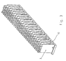
- Fig. 1 is a complete connector part 1 in the assembled state shown. It essentially consists of a rectangular support body 19 made of plastic with moldings for several used side by side Segments 2, to which connection ends 4 and contacts 5 are attached are (see Fig. 2) by an additional part 3 in a defined position be held.
- the additional part 3 is designed so that it is not from the volume defined by the side walls of the carrier body 19 protrudes, i.e. the total volume of the connector part is by the additional part 3 is not enlarged.
- the connector part shown in Fig. 1 1 is a multipole female connector with contacts, which are designed as contact springs and in the formations 20 of the carrier body 19 are used.
- the invention can also be applied to a Male connector with a bottom part with formations can be applied in the segments with contact blades are used and the one with the Mating area of the contact elements surrounding the collar is provided.
- FIG. 2 shows a single segment 2 of the connector part 1 from FIG. 1. It consists of insulating material into which the connection ends 4, which are connected to a PCB (not shown) to be connected, are embedded.
- the Terminal ends 4 are arranged at right angles to the contact springs 5.
- the Segment has a first end surface facing away from the contact springs 5 16 with a shoulder 18 and one of these first end surface 16 opposite second end surface 11. In the first end surface 16 there is a groove 9 transverse to its longitudinal direction.
- Recesses 20 are formed in the bar, which are each limited by a stop 10.
- the support wall 21 has a plurality of locking recesses 14 on.
- the additional part 3 made of insulating material is according to the view of FIG inserted at the bottom into the carrier body 19, in which the segments 2 also used from below with contact springs 5 pointing upwards have been.
- the resilient locking lugs 12 of the additional part 3 snap in the corresponding locking recesses 14 in the support wall 21 of the Carrier body 19 a.
- the projections 7 of the additional part 3 hold when fully assembled Connector part 1, the contact springs 5 of the segments 2 firmly in position.
- the bent contact springs 5 of the segments 2 come into engagement with the formations 7, with which a reliable contact with contact blades a complementary connector part (not shown) in the carrier body 19 is guaranteed.
- the additional part 3 presses with its contact surface 15 on the first end surface 16 of each segment 2 and presses thus each segment 2 with its second end face 11 on the associated Stop 10 of the carrier body 19. This is the insertion depth of the Segments 2 are precisely defined in the carrier body 19.
- each in the groove 9 of a segment 2 grabs the segments 2 of the additional part 3 in the transverse direction held in relation to the direction of insertion.
- the outermost segments of the spring connector part are each by the projection 17 in Border area of the additional part 3 recorded in paragraph 18 of the corresponding Segment 2 comes to rest.
- Secure locking of the additional part 3 is achieved by the molded lugs 25, which are in the recesses 26 engage in the ribs 23 of the support wall 21 of the carrier body 19.
- the pin-shaped projections 27 provided on the additional part 3, which together with the contact springs 5 of the Segments 2 protrude into the formations 20 of the carrier body 19.
- the connector part 1 described is designed so that the removal of the additional part 3, the segments 2 are not held in the carrier body 19 become. This makes disassembly quick and easy.
- can also be used for simplified assembly of the plug-in connection part 1 means for the cohesion of the segments 2 with the support body 19 may be provided so that they hold together without the additional part 3 and so form a preassembled unit.
Landscapes
- Connector Housings Or Holding Contact Members (AREA)
- Coupling Device And Connection With Printed Circuit (AREA)
- Details Of Connecting Devices For Male And Female Coupling (AREA)
Abstract
Bei einem elektrischen Steckverbindungsteil, das einen Trägerkörper (19) aus Isoliermaterial und mehrere in den Trägerkörper (19) eingesetzte Segmente (2) mit Kontakten (5) und Anschlußenden (4) enthält, soll der Halt der Segmente in dem Trägerkörper verbessert werden. Zu diesem Zweck ist ein Zusatzteil (3) aus Isoliermaterial vorgesehen, das die Segmente (2) im Trägerkörper (19) fixiert und mit kammartigen Anformungen (24) versehen ist, die zwischen den Segmenten (2) angeordnet sind. <IMAGE>In the case of an electrical plug connection part which contains a carrier body (19) made of insulating material and a plurality of segments (2) with contacts (5) and connecting ends (4) inserted into the carrier body (19), the retention of the segments in the carrier body is to be improved. For this purpose, an additional part (3) made of insulating material is provided, which fixes the segments (2) in the carrier body (19) and is provided with comb-like projections (24) which are arranged between the segments (2). <IMAGE>
Description
Die Erfindung betrifft ein elektrisches Steckverbindungsteil, das einen Trägerkörper aus Isoliermaterial und mehrere in den Trägerkörper eingesetzte Segmente mit Kontakten und Anschlußenden enthält.The invention relates to an electrical connector part, which has a carrier body made of insulating material and several inserted into the carrier body Contains segments with contacts and connection ends.
In ein solches Steckverbindungsteil, das als Feder- oder Messerleiste ausgebildet sein kann, wird ein komplementäres Steckverbindungsteil zur Herstellung einer mehrpoligen Steckverbindung eingesteckt. Die nebeneinander in den Trägerkörper des Steckverbindungsteils eingesetzten Segmente weisen auf der Seite, die in den Trägerkörper eingeführt wird, Kontakte auf, die bei einer Federleiste als Kontaktfedern oder bei einer Messerleiste als Kontaktmesser ausgebildet und zur Bewerkstelligung des Kontakts mit den entsprechenden Kontaktmessern bzw. Kontaktfedern des komplementären Steckverbindungsteils vorgesehen sind. Auf einer anderen Seite der Segmente sind mit den jeweiligen Kontakten verbundene Anschlußenden ausgebildet, die beispielsweise mit Anschlüssen einer Leiterplatte verbunden werden können. Dabei können die Anschlußenden rechtwinklig zur Steckrichtung des Steckverbinders angeordnet werden.In such a connector part, which is designed as a spring or knife strip can be a complementary connector part for manufacturing a multi-pin connector. The side by side have segments used in the carrier body of the connector part on the side that is inserted into the carrier body, contacts on the with a female connector as contact springs or with a male connector as contact knife trained and to establish contact with the appropriate Contact knives or contact springs of the complementary Plug connector part are provided. On another side of the segments connection ends connected to the respective contacts are formed, which are connected, for example, to connections on a printed circuit board can be. The connection ends can be perpendicular to the direction of insertion of the connector can be arranged.
Die Segmente mit ihren Kontakten und Anschlußenden werden in verschiedenen Variationen hergestellt. Bei einer Herstellungsmethode werden die Kontakte umspritzt, was jedoch relativ kostenaufwendig ist. Bei einer anderen Methode sind die Segmente zweiteilig ausgeführt, und die Kontakte werden zwischen die zwei Segmenthälften eingelegt. Dies hat jedoch den Nachteil, daß insgesamt deutlich mehr Einzelteile verarbeitet werden müssen. Schließlich können die Kontakte auch einfach in Scheibchen eingelegt sein, was sich jedoch nachteilig auf deren Festsitz auswirkt.The segments with their contacts and connection ends are in different Variations made. In a manufacturing method, the Injection molded contacts, which is relatively expensive. Another one Method, the segments are made in two parts, and the contacts inserted between the two segment halves. However, this has the Disadvantage that significantly more individual parts have to be processed. Finally, the contacts can also simply be inserted into discs be, which however has an adverse effect on their tight fit.
Aus der deutschen Offenlegungsschrift 196 34 844 sowie der deutschen Patentschrift 195 33 295 sind Gehäuse bekannt, in die ein Innengehäuse eingesetzt werden kann. Es wird ein Deckel bzw. eine Verschlußkappe verwendet, um die Innengehäuse in dem eigentlichen Gehäuse festzulegen.From German Offenlegungsschrift 196 34 844 and the German one Patent 195 33 295 housing are known in which an inner housing can be used. A lid or a sealing cap is used, to fix the inner case in the actual case.
Die Aufgabe der Erfindung besteht darin, ein elektrisches Steckverbindungsteil in Segmenttechnik zu schaffen, bei dem die Segmente im Steckverbindungsteil sicher, präzise und fest installiert sind bei einfacher und damit kostengünstiger Montage.The object of the invention is an electrical connector part to create in segment technology, in which the segments in the connector part are safe, precise and permanently installed with simpler and therefore cheaper Assembly.
Diese Aufgabe wird durch ein elektrisches Steckverbindungsteil gelöst, das einen Trägerkörper aus Isoliermaterial und mehrere in den Trägerkörper eingesetzte Segmente mit Kontakten und Anschlußenden enthält, wobei ein Zusatzteil aus Isoliermaterial vorgesehen ist, das die Segmente im Trägerkörper fixiert und mit kammartigen Anformungen versehen ist, die zwischen den Segmenten angeordnet sind. Ein solches Zusatzteil bewirkt einen festen Halt der Segmente im Trägerkörper und hat den Vorteil, daß es zusätzlich zur Isolierung der Segmente untereinander dient und damit zu einer Verbesserung hinsichtlich der bei Steckverbindern unerwünschten erforderlichen Luft- und Kriechstrecken im Steckverbinder führt.This object is achieved by an electrical plug-in connection part a carrier body made of insulating material and several in the carrier body contains inserted segments with contacts and connection ends, where a Additional part made of insulating material is provided, the segments in the carrier body fixed and provided with comb-like formations that between the segments are arranged. Such an additional part causes a firm Hold the segments in the carrier body and has the advantage that it is additional serves to isolate the segments from one another and thus to improve them with regard to the undesirable required with connectors Clearances and creepage distances in the connector leads.
Vorzugsweise sind die Anschlußenden der Segmente rechtwinklig zur Einsteckrichtung der Kontakte verbindbar, um eine vorteilhafte Steckverbindungskonfiguration zu erreichen, bei der die Anschlußenden der Segmente rechtwinklig zur Steckrichtung des Steckverbindungsteils z.B. in entsprechende Bohrungen einer Leiterplatte ragen. Dadurch kann ein Steckverbindungsteil platzsparend in Längsrichtung der Platine aufgesteckt werden. The connection ends of the segments are preferably at right angles to the direction of insertion the contacts connectable to an advantageous connector configuration to achieve at the connecting ends of the segments perpendicular to the direction of insertion of the connector part e.g. in corresponding Holes of a PCB protrude. This allows a connector part space-saving in the longitudinal direction of the board.
Zudem erweist es sich als vorteilhaft, Anformungen am Zusatzteil zur Fixierung der Kontakte der in den Trägerkörper eingesetzten Segmente vorzusehen, um deren exakte Positionierung zu ermöglichen. Dies ist insbesondere dann leicht zu verwirklichen, wenn die Kontakte abgekröpft sind und in Eingriff mit den Anformungen am Zusatzteil kommen. Dann ist für eine zuverlässige Kontaktierung der Segmentkontakte mit den entsprechenden Kontakten des komplementären Steckverbindungsteils gesorgt.In addition, it proves to be advantageous to form on the additional part for fixation to provide the contacts of the segments inserted in the carrier body, to enable their exact positioning. This is particularly so then easy to implement when the contacts are cranked and engaged come with the formations on the additional part. Then for a reliable one Contacting the segment contacts with the corresponding contacts of the complementary connector part.
Durch verschiedene zusätzliche Maßnahmen kann eine noch bessere Fixierung der Segmente und deren Kontakte erreicht werden. So kann etwa das Zusatzteil mit einer Auflagefläche auf eine erste, von den Kontakten abgewandte Abschlußfläche eines jeden Segments drücken und damit das Segment mit einer der ersten Abschlußfläche gegenüberliegenden zweiten Abschlußfläche auf einen Anschlag des Trägerkörpers drücken, wodurch die Einstecktiefe der Segmente in den Trägerkörper festgelegt wird. Eine Fixierung der Segmente quer zu deren Einsteckrichtung ist durch rippenförmige Anformungen am Zusatzteil möglich, die jeweils in eine entsprechende Ausnehmnung in der ersten Abschlußfläche eines Segments eingreifen. Schließlich können die äußeren Segmente des Steckverbindungsteils vorzugsweise durch einen Vorsprung in der Auflagefläche des Zusatzteils festgehalten werden, der in einen entsprechenden Absatz der ersten Abschlußfläche eines Segments eingreift.Various additional measures can improve fixation of the segments and their contacts can be reached. This can be about Additional part with a contact surface on a first, facing away from the contacts Press the end surface of each segment and thus the segment with a second end surface opposite the first end surface press on a stop of the carrier body, whereby the Insertion depth of the segments in the carrier body is determined. A fixation the segments transverse to their direction of insertion is rib-shaped Formations on the additional part possible, each in a corresponding recess engage in the first end face of a segment. Finally, the outer segments of the connector part can preferably held by a projection in the support surface of the additional part be in a corresponding paragraph of the first end area of a segment engages.
Für einen optimalen Festsitz des Zusatzteils im Trägerkörper weist das Zusatzteil bevorzugt federnde Rastnasen auf, die in entsprechende Rastausnehmungen des Trägerkörpers einrasten und so eine feste Arretierung ermöglichen. Zu diesem Zweck kann auch eine Stützwand im Trägerkörper mit Rippen vorgesehen sein, wobei die Rippen jeweils eine Aussparung aufweisen, in die eine entsprechende angeformte Nase des Zusatzteils eingreift.For an optimal tight fit of the additional part in the carrier body, the additional part preferably resilient locking lugs, which in corresponding locking recesses engage the carrier body and thus enable a firm locking. For this purpose, a support wall can also be provided in the carrier body Ribs may be provided, the ribs each having a recess, into which a corresponding molded nose of the additional part engages.
Schließlich erweist es sich für eine schnelle und einfache Demontage des Steckverbindungsteils in seine Einzelteile als vorteilhaft, wenn der Trägerkörper und die Segmente nur durch das Zusatzteil zusammengehalten werden.Finally, it turns out to be a quick and easy disassembly of the Plug connector part in its individual parts as advantageous if the carrier body and the segments are held together only by the additional part.
Weitere Merkmale und Vorteile der Erfindung ergeben sich aus der folgenden Beschreibung einer bevorzugten Ausführungsform unter Bezugnahme auf die Zeichnung. In der Zeichnung zeigen:
- Figur 1
- eine perspektivische Ansicht eines elektrischen Steckverbindungsteils, das als Federleiste ausgebildet ist,
Figur 2- eine perspektivische Ansicht eines Segments, das bei dem in Fig. 1 gezeigten Steckverbindungsteil verwendet wird
Figur 3- eine perspektivische Ansicht eines Zusatzteils, das bei dem in Fig. 1 gezeigten Steckverbindungsteil verwendet wird
- Figur 3a
- in vergrößertem Maßstab einen Ausschnitt des Zusatzteils aus
Figur 3, und Figur 4- in vergrößertem Maßstab perspektivisch einen Ausschnitt eines Trägerkörpers, der bei dem in Fig. 1 gezeigten Steckverbindungsteil verwendet wird.
- Figure 1
- 2 shows a perspective view of an electrical plug-in connection part which is designed as a female connector,
- Figure 2
- a perspective view of a segment used in the connector shown in Fig. 1
- Figure 3
- a perspective view of an additional part, which is used in the connector part shown in Fig. 1
- Figure 3a
- on an enlarged scale a section of the additional part from Figure 3, and
- Figure 4
- in an enlarged scale, a perspective view of a section of a carrier body which is used in the connector part shown in FIG. 1.
In Fig. 1 ist ein komplettes Steckverbindungsteil 1 im montierten Zustand
dargestellt. Er besteht im wesentlichen aus einem rechteckförmigen Trägerkörper
19 aus Kunststoff mit Ausformungen für mehrere nebeneinander eingesetzte
Segmente 2, an welchen Anschlußenden 4 und Kontakte 5 angebracht
sind (siehe Fig. 2), die durch ein Zusatzteil 3 in definierter Position
festgehalten werden. Dabei ist das Zusatzteil 3 so ausgelegt, daß es nicht
aus dem durch die Seitenwände des Trägerkörpers 19 definierten Volumen
herausragt, d.h. das Gesamtvolumen des Steckverbindungsteils wird durch
das Zusatzteil 3 nicht vergrößert. Bei dem in Fig. 1 abgebildeten Steckverbindungsteil
1 handelt es sich um eine mehrpolige Federleiste mit Kontakten,
die als Kontaktfedern ausgebildet und in Ausformungen 20 des Trägerkörpers
19 eingesetzt sind. Die Erfindung kann jedoch genauso auf eine
Messerleiste mit einem Bodenteil mit Ausformungen angewandt werden, in
die Segmente mit Kontaktmessern eingesetzt sind und bei der ein den
Steckbereich der Kontaktelemente umgebender Kragen vorgesehen ist.In Fig. 1 is a complete connector part 1 in the assembled state
shown. It essentially consists of a
Fig. 2 zeigt ein einzelnes Segment 2 des Steckverbindungsteils 1 aus Fig. 1.
Es besteht aus Isoliermaterial, in das die Anschlußenden 4, die mit einer
Leiterplatte (nicht gezeigt) verbunden werden sollen, eingebettet sind. Die
Anschlußenden 4 sind rechtwinklig zu den Kontaktfedern 5 angeordnet. Das
Segment besitzt eine erste, von den Kontaktfedern 5 abgewandte Abschlußfläche
16 mit einem Absatz 18 und eine dieser ersten Abschlußfläche 16 gegenüberliegende
zweite Abschlußfläche 11. In der ersten Abschlußfläche 16
befindet sich quer zu deren Längsrichtung eine Nut 9.FIG. 2 shows a
Das in Fig. 3 und im Detail in Fig. 3a dargestellte längliche Zusatzteil 3 des
Steckverbindungsteils 1 aus Figur 1 hat eine kammartige Struktur, wobei einige
der von einer Auflagefläche 15 ausgehenden kammartigen Anformungen
24 seitlich federnde Rastnasen 12 aufweisen. Auf der Längsseite jeder
kammartigen Anformung 24 ist an der Auflagefläche 15 jeweils eine Nase 25
angebracht. An den von der Auflagefläche 15 entfernten Enden der kammartigen
Anformungen 24 sind Anformungen 7 und stiftförmige Anformungen
27 vorgesehen. An den Längsenden des Zusatzteils 3 weist die Auflagefläche
jeweils einen Vorsprung 17 und eine rippenförmige Anformung 8
auf.The elongated
In Fig. 4 ist ein vergrößerter Ausschnitt des Trägerteils 19 des Steckverbindungsteils
1 aus Fig. 1 zu sehen. In der Leiste sind Ausnehmungen 20 gebildet,
die jeweils durch einen Anschlag 10 begrenzt sind. Seitlich ist eine
Stützwand 21 vorgesehen, an die Rippen 23 mit Aussparungen 26 angeformt
sind. Außerdem weist die Stützwand 21 mehrere Rastausnehmungen
14 auf.4 is an enlarged section of the
Das Zusatzteil 3 aus Isoliermaterial wird gemäß der Ansicht der Fig. 1 von
unten in den Trägerkörper 19 gesteckt, in welchen zuvor die Segmente 2
ebenfalls von unten mit nach oben weisenden Kontaktfedern 5 eingesetzt
worden sind. Die federnden Rastnasen 12 des Zusatzteils 3 schnappen dabei
in die entsprechenden Rastausnehmungen 14 in der Stützwand 21 des
Trägerkörpers 19 ein. Zwischen den Rippen 23 stützen sich einerseits die
Segmente 2 und andererseits auch die kammähnlichen Anformungen 24 des
Zusatzteils 3 ab. Damit ist für eine sichere Arretierung der Segmente 2 gesorgt.
Die Anformungen 7 des Zusatzteils 3 halten beim fertigmontierten
Steckverbindungsteil 1 die Kontaktfedern 5 der Segmente 2 fest in Position.
Dabei kommen die abgekröpften Kontaktfedern 5 der Segmente 2 in Eingriff
mit den Anformungen 7, womit eine sichere Kontaktierung mit Kontaktmessern
eines komplementären Steckverbindungsteils (nicht gezeigt) im Trägerkörper
19 gewährleistet wird. Das Zusatzteil 3 drückt mit seiner Auflagefläche
15 auf die erste Abschlußfläche 16 eines jeden Segments 2 und drückt
somit jedes Segment 2 mit seiner zweiten Abschlußfläche 11 auf den zugehörigen
Anschlag 10 des Trägerkörpers 19. Dadurch ist die Einstecktiefe der
Segmente 2 in den Trägerkörper 19 genau festgelegt.The
Mit den rippenförmigen Anformungen 8, die jeweils in die Nut 9 eines Segments
2 greifen, werden die Segmente 2 von dem Zusatzteil 3 in Querrichtung
bezogen auf die Einsteckrichtung gehalten. Die äußersten Segmente
des Federsteckverbindungsteils werden jeweils durch den Vorsprung 17 im
Randbereich des Zusatzteils 3 festgehalten, der in dem Absatz 18 des entsprechenden
Segments 2 zu liegen kommt. Eine sichere Arretierung des Zusatzteils
3 wird durch die angeformten Nasen 25 erreicht, die in die Aussparungen
26 in den Rippen 23 der Stützwand 21 des Trägerkörpers 19 greifen.
Zum selben Zweck sind zusätzlich noch die stiftförmigen Anformungen 27
am Zusatzteil 3 vorgesehen, die zusammen mit den Kontaktfedern 5 der
Segmente 2 in die Ausformungen 20 des Trägerkörpers 19 ragen.With the rib-shaped
Das beschriebene Steckverbindungsteil 1 ist so konzipiert, daß bei der Entfernung
des Zusatzteils 3 die Segmente 2 nicht im Trägerkörper 19 festgehalten
werden. Dadurch ist eine schnelle und einfach Demontage möglich.
Alternativ können jedoch auch für eine vereinfachte Montage des Steckverbindungsteils
1 Mittel für den Zusammenhalt der Segmente 2 mit dem Trägerkörper
19 vorgesehen sein, so daß diese ohne das Zusatzteil 3 zusammenhalten
und so eine vormontierbare Einheit bilden.The connector part 1 described is designed so that the removal
of the
Claims (10)
Applications Claiming Priority (3)
| Application Number | Priority Date | Filing Date | Title |
|---|---|---|---|
| DE19825971A DE19825971C1 (en) | 1998-06-10 | 1998-06-10 | Multipin electrical plug connector, e.g. for printed circuit board |
| DE19825971 | 1998-06-10 | ||
| US09/326,259 US6196853B1 (en) | 1998-06-10 | 1999-06-04 | Electric plug connector |
Publications (3)
| Publication Number | Publication Date |
|---|---|
| EP0964480A2 true EP0964480A2 (en) | 1999-12-15 |
| EP0964480A3 EP0964480A3 (en) | 2002-03-13 |
| EP0964480B1 EP0964480B1 (en) | 2003-09-17 |
Family
ID=26046737
Family Applications (1)
| Application Number | Title | Priority Date | Filing Date |
|---|---|---|---|
| EP99110539A Expired - Lifetime EP0964480B1 (en) | 1998-06-10 | 1999-06-01 | Electrical connector element |
Country Status (4)
| Country | Link |
|---|---|
| US (1) | US6196853B1 (en) |
| EP (1) | EP0964480B1 (en) |
| JP (1) | JP3117965B2 (en) |
| DE (1) | DE19825971C1 (en) |
Families Citing this family (23)
| Publication number | Priority date | Publication date | Assignee | Title |
|---|---|---|---|---|
| DE69809438T2 (en) * | 1997-08-20 | 2003-07-10 | Berg Electronics Mfg. B.V., 's-Hertogenbosch | ELECTRICAL, MODULAR CONNECTORS FOR HIGH TRANSMISSION SPEEDS AND RELATED RECEIVING PART |
| DE20003951U1 (en) * | 2000-03-08 | 2001-07-12 | Bosch Gmbh Robert | Multipole electrical connector |
| US6709298B2 (en) * | 2001-04-06 | 2004-03-23 | Litton Systems, Inc. | Insulator coring and contact configuration to prevent pin stubbing in the throat of tuning fork socket connector contacts |
| US6979215B2 (en) | 2001-11-28 | 2005-12-27 | Molex Incorporated | High-density connector assembly with flexural capabilities |
| US6743057B2 (en) * | 2002-03-27 | 2004-06-01 | Tyco Electronics Corporation | Electrical connector tie bar |
| US6764349B2 (en) * | 2002-03-29 | 2004-07-20 | Teradyne, Inc. | Matrix connector with integrated power contacts |
| US6638079B1 (en) * | 2002-05-21 | 2003-10-28 | Hon Hai Precision Ind. Co., Ltd. | Customizable electrical connector |
| JP3929931B2 (en) * | 2003-05-13 | 2007-06-13 | 株式会社オートネットワーク技術研究所 | Connector press-fitting jig |
| US6884117B2 (en) * | 2003-08-29 | 2005-04-26 | Hon Hai Precision Ind. Co., Ltd. | Electrical connector having circuit board modules positioned between metal stiffener and a housing |
| US7976345B2 (en) * | 2005-12-15 | 2011-07-12 | Tyco Electronics Corporation | Electrical contact assembly and method of manufacturing thereof |
| DE202006016424U1 (en) * | 2006-10-20 | 2007-01-04 | Phoenix Contact Gmbh & Co. Kg | Electric contact device with an insulating housing with fastening recesses in which the contacts engage |
| CN107069274B (en) | 2010-05-07 | 2020-08-18 | 安费诺有限公司 | High performance cable connector |
| CN104704682B (en) | 2012-08-22 | 2017-03-22 | 安费诺有限公司 | High-frequency electrical connector |
| US9450344B2 (en) | 2014-01-22 | 2016-09-20 | Amphenol Corporation | High speed, high density electrical connector with shielded signal paths |
| WO2017007429A1 (en) | 2015-07-07 | 2017-01-12 | Amphenol Fci Asia Pte. Ltd. | Electrical connector |
| US10243304B2 (en) | 2016-08-23 | 2019-03-26 | Amphenol Corporation | Connector configurable for high performance |
| CN208862209U (en) | 2018-09-26 | 2019-05-14 | 安费诺东亚电子科技(深圳)有限公司 | A kind of connector and its pcb board of application |
| CN110620300A (en) * | 2019-05-21 | 2019-12-27 | 中航光电科技股份有限公司 | Connector fixing piece and connector |
| CN115428275A (en) | 2020-01-27 | 2022-12-02 | 富加宜(美国)有限责任公司 | High speed connector |
| US11469554B2 (en) | 2020-01-27 | 2022-10-11 | Fci Usa Llc | High speed, high density direct mate orthogonal connector |
| CN215816516U (en) | 2020-09-22 | 2022-02-11 | 安费诺商用电子产品(成都)有限公司 | Electrical connector |
| CN213636403U (en) | 2020-09-25 | 2021-07-06 | 安费诺商用电子产品(成都)有限公司 | Electrical connector |
| KR102675292B1 (en) * | 2022-01-17 | 2024-06-14 | 류기택 | Apparatus for boiling noodle |
Citations (4)
| Publication number | Priority date | Publication date | Assignee | Title |
|---|---|---|---|---|
| EP0422785A2 (en) * | 1989-10-10 | 1991-04-17 | The Whitaker Corporation | Impedance matched backplane connector |
| EP0486298A1 (en) * | 1990-11-15 | 1992-05-20 | The Whitaker Corporation | Multicontact connector for signal transmission |
| US5199886A (en) * | 1991-11-19 | 1993-04-06 | Amp Incorporated | Shrouded connector assembly |
| EP0560551A1 (en) * | 1992-03-09 | 1993-09-15 | The Whitaker Corporation | Shielded back plane connector |
Family Cites Families (6)
| Publication number | Priority date | Publication date | Assignee | Title |
|---|---|---|---|---|
| DE19533295C1 (en) * | 1995-09-08 | 1997-04-10 | Siemens Ag | Hybrid connector with modular electrical and fiber optic connectors |
| US5716237A (en) * | 1996-06-21 | 1998-02-10 | Lucent Technologies Inc. | Electrical connector with crosstalk compensation |
| US6010373A (en) * | 1996-06-26 | 2000-01-04 | Robinson Nugent, Inc. | Electrical connector interlocking apparatus |
| DE19634844C2 (en) * | 1996-08-28 | 1998-10-15 | Siemens Ag | Connector with lockable cover part |
| US5924899A (en) * | 1997-11-19 | 1999-07-20 | Berg Technology, Inc. | Modular connectors |
| US5961355A (en) * | 1997-12-17 | 1999-10-05 | Berg Technology, Inc. | High density interstitial connector system |
-
1998
- 1998-06-10 DE DE19825971A patent/DE19825971C1/en not_active Expired - Lifetime
-
1999
- 1999-06-01 EP EP99110539A patent/EP0964480B1/en not_active Expired - Lifetime
- 1999-06-04 US US09/326,259 patent/US6196853B1/en not_active Expired - Lifetime
- 1999-06-07 JP JP15986899A patent/JP3117965B2/en not_active Expired - Fee Related
Patent Citations (4)
| Publication number | Priority date | Publication date | Assignee | Title |
|---|---|---|---|---|
| EP0422785A2 (en) * | 1989-10-10 | 1991-04-17 | The Whitaker Corporation | Impedance matched backplane connector |
| EP0486298A1 (en) * | 1990-11-15 | 1992-05-20 | The Whitaker Corporation | Multicontact connector for signal transmission |
| US5199886A (en) * | 1991-11-19 | 1993-04-06 | Amp Incorporated | Shrouded connector assembly |
| EP0560551A1 (en) * | 1992-03-09 | 1993-09-15 | The Whitaker Corporation | Shielded back plane connector |
Also Published As
| Publication number | Publication date |
|---|---|
| EP0964480B1 (en) | 2003-09-17 |
| US6196853B1 (en) | 2001-03-06 |
| JP2000012173A (en) | 2000-01-14 |
| JP3117965B2 (en) | 2000-12-18 |
| EP0964480A3 (en) | 2002-03-13 |
| DE19825971C1 (en) | 1999-11-11 |
Similar Documents
| Publication | Publication Date | Title |
|---|---|---|
| DE19825971C1 (en) | Multipin electrical plug connector, e.g. for printed circuit board | |
| DE3688901T2 (en) | Connectors for circuit boards, circuit board assembly using this connector and method of manufacturing this circuit board assembly. | |
| DE60027611T2 (en) | Cable connector with controlled impedance | |
| DE102009022094B4 (en) | stacking connector | |
| DE60000187T2 (en) | Coaxial connector for connecting two circuit boards | |
| DE69520197T2 (en) | Arrangement for floating mounting of an electrical connector on a plate | |
| DE69300865T3 (en) | ELECTRICAL CONNECTOR WITH SHEET AS PLUG-IN CONTACT MATERIAL. | |
| DE69508569T2 (en) | SECONDARY INTERLOCKING ELEMENT | |
| DE69324334T2 (en) | Electrical connector assembly with connector alignment system | |
| DE60221427T2 (en) | Cast electrical connector | |
| EP3375048B1 (en) | Plug contact | |
| DE2809830A1 (en) | ELECTRICAL CONNECTOR | |
| EP1391965A1 (en) | Spring clamp terminal for electrical conductor | |
| DE2234961C3 (en) | Process for the production of connectors for circuit boards | |
| DE2230337A1 (en) | ELECTRICAL CONNECTOR ARRANGEMENT | |
| EP1429423B1 (en) | Electrical plug connector having a casing and a heavy current contact | |
| DE102004020422A1 (en) | Pin for solderless electrical connection to a circuit board, a press tool and method for producing a solderless electrical connection | |
| DE1956095C3 (en) | Electrical multiple connector | |
| DE1765978B1 (en) | CIRCUIT BLOCK FOR ELECTRICAL CONNECTION USING PLUG CONNECTIONS OF ELECTRICAL CIRCUIT ELEMENTS | |
| DE69600062T2 (en) | Electrical connector | |
| DE3925958C1 (en) | Plug connector insertable in metallised bores of PCB - has parallel rows of contact element at right angles to insertion direction of counter-plug for other appts. | |
| DE4018978C2 (en) | Slide switch | |
| DE102018203970A1 (en) | Bridge element for producing an electrical connection and arrangement | |
| DE4332996C2 (en) | Connector for contacting a circuit board | |
| DE2842892A1 (en) | ELECTRIC CONNECTOR |
Legal Events
| Date | Code | Title | Description |
|---|---|---|---|
| PUAI | Public reference made under article 153(3) epc to a published international application that has entered the european phase |
Free format text: ORIGINAL CODE: 0009012 |
|
| AK | Designated contracting states |
Kind code of ref document: A2 Designated state(s): AT BE CH CY DE DK ES FI FR GB GR IE IT LI LU MC NL PT SE Kind code of ref document: A2 Designated state(s): DE FI FR GB IT SE |
|
| AX | Request for extension of the european patent |
Free format text: AL;LT;LV;MK;RO;SI |
|
| PUAL | Search report despatched |
Free format text: ORIGINAL CODE: 0009013 |
|
| AK | Designated contracting states |
Kind code of ref document: A3 Designated state(s): AT BE CH CY DE DK ES FI FR GB GR IE IT LI LU MC NL PT SE |
|
| AX | Request for extension of the european patent |
Free format text: AL;LT;LV;MK;RO;SI |
|
| 17P | Request for examination filed |
Effective date: 20020408 |
|
| 17Q | First examination report despatched |
Effective date: 20020614 |
|
| GRAH | Despatch of communication of intention to grant a patent |
Free format text: ORIGINAL CODE: EPIDOS IGRA |
|
| GRAH | Despatch of communication of intention to grant a patent |
Free format text: ORIGINAL CODE: EPIDOS IGRA |
|
| AKX | Designation fees paid |
Free format text: DE FI FR GB IT SE |
|
| GRAH | Despatch of communication of intention to grant a patent |
Free format text: ORIGINAL CODE: EPIDOS IGRA |
|
| RIC1 | Information provided on ipc code assigned before grant |
Ipc: 7H 01R 12/18 B Ipc: 7H 01R 13/518 A |
|
| GRAA | (expected) grant |
Free format text: ORIGINAL CODE: 0009210 |
|
| AK | Designated contracting states |
Kind code of ref document: B1 Designated state(s): DE FI FR GB IT SE |
|
| REG | Reference to a national code |
Ref country code: GB Ref legal event code: FG4D Free format text: NOT ENGLISH |
|
| REF | Corresponds to: |
Ref document number: 59906990 Country of ref document: DE Date of ref document: 20031023 Kind code of ref document: P |
|
| REG | Reference to a national code |
Ref country code: IE Ref legal event code: FG4D Free format text: GERMAN |
|
| RAP2 | Party data changed (patent owner data changed or rights of a patent transferred) |
Owner name: HARTING ELECTRONICS GMBH & CO. KG |
|
| REG | Reference to a national code |
Ref country code: SE Ref legal event code: TRGR |
|
| REG | Reference to a national code |
Ref country code: GB Ref legal event code: 732E |
|
| GBT | Gb: translation of ep patent filed (gb section 77(6)(a)/1977) |
Effective date: 20040123 |
|
| REG | Reference to a national code |
Ref country code: IE Ref legal event code: FD4D |
|
| ET | Fr: translation filed | ||
| PLBE | No opposition filed within time limit |
Free format text: ORIGINAL CODE: 0009261 |
|
| STAA | Information on the status of an ep patent application or granted ep patent |
Free format text: STATUS: NO OPPOSITION FILED WITHIN TIME LIMIT |
|
| 26N | No opposition filed |
Effective date: 20040618 |
|
| REG | Reference to a national code |
Ref country code: FR Ref legal event code: PLFP Year of fee payment: 18 |
|
| PGFP | Annual fee paid to national office [announced via postgrant information from national office to epo] |
Ref country code: FI Payment date: 20160609 Year of fee payment: 18 |
|
| REG | Reference to a national code |
Ref country code: FR Ref legal event code: PLFP Year of fee payment: 19 |
|
| PGFP | Annual fee paid to national office [announced via postgrant information from national office to epo] |
Ref country code: CH Payment date: 20170912 Year of fee payment: 10 |
|
| PG25 | Lapsed in a contracting state [announced via postgrant information from national office to epo] |
Ref country code: FI Free format text: LAPSE BECAUSE OF NON-PAYMENT OF DUE FEES Effective date: 20170601 |
|
| REG | Reference to a national code |
Ref country code: FR Ref legal event code: PLFP Year of fee payment: 20 |
|
| PGFP | Annual fee paid to national office [announced via postgrant information from national office to epo] |
Ref country code: FR Payment date: 20180628 Year of fee payment: 20 |
|
| PGFP | Annual fee paid to national office [announced via postgrant information from national office to epo] |
Ref country code: DE Payment date: 20180831 Year of fee payment: 20 Ref country code: GB Payment date: 20180629 Year of fee payment: 20 Ref country code: IT Payment date: 20180622 Year of fee payment: 20 |
|
| REG | Reference to a national code |
Ref country code: SE Ref legal event code: EUG |
|
| PG25 | Lapsed in a contracting state [announced via postgrant information from national office to epo] |
Ref country code: SE Free format text: LAPSE BECAUSE OF NON-PAYMENT OF DUE FEES Effective date: 20180602 |
|
| REG | Reference to a national code |
Ref country code: DE Ref legal event code: R071 Ref document number: 59906990 Country of ref document: DE |
|
| REG | Reference to a national code |
Ref country code: GB Ref legal event code: PE20 Expiry date: 20190531 |
|
| PG25 | Lapsed in a contracting state [announced via postgrant information from national office to epo] |
Ref country code: GB Free format text: LAPSE BECAUSE OF EXPIRATION OF PROTECTION Effective date: 20190531 |