EP0962301A2 - Méthode de fabrication de disques optiques - Google Patents
Méthode de fabrication de disques optiques Download PDFInfo
- Publication number
- EP0962301A2 EP0962301A2 EP99110589A EP99110589A EP0962301A2 EP 0962301 A2 EP0962301 A2 EP 0962301A2 EP 99110589 A EP99110589 A EP 99110589A EP 99110589 A EP99110589 A EP 99110589A EP 0962301 A2 EP0962301 A2 EP 0962301A2
- Authority
- EP
- European Patent Office
- Prior art keywords
- transmittance
- disc
- disc substrates
- bonded
- turntable
- Prior art date
- Legal status (The legal status is an assumption and is not a legal conclusion. Google has not performed a legal analysis and makes no representation as to the accuracy of the status listed.)
- Withdrawn
Links
- 230000003287 optical effect Effects 0.000 title claims description 36
- 238000004519 manufacturing process Methods 0.000 title claims description 18
- 239000000758 substrate Substances 0.000 claims description 115
- 238000002834 transmittance Methods 0.000 claims description 106
- 239000000853 adhesive Substances 0.000 claims description 40
- 230000001070 adhesive effect Effects 0.000 claims description 40
- 238000000034 method Methods 0.000 claims description 24
- 238000009281 ultraviolet germicidal irradiation Methods 0.000 claims description 19
- 238000003892 spreading Methods 0.000 claims description 11
- 230000001678 irradiating effect Effects 0.000 claims description 5
- VYPSYNLAJGMNEJ-UHFFFAOYSA-N Silicium dioxide Chemical compound O=[Si]=O VYPSYNLAJGMNEJ-UHFFFAOYSA-N 0.000 claims description 3
- 238000001723 curing Methods 0.000 description 18
- 238000007689 inspection Methods 0.000 description 6
- 229920005989 resin Polymers 0.000 description 6
- 239000011347 resin Substances 0.000 description 6
- 238000003860 storage Methods 0.000 description 5
- 230000003247 decreasing effect Effects 0.000 description 4
- 230000033001 locomotion Effects 0.000 description 4
- 238000003848 UV Light-Curing Methods 0.000 description 3
- PXHVJJICTQNCMI-UHFFFAOYSA-N Nickel Chemical compound [Ni] PXHVJJICTQNCMI-UHFFFAOYSA-N 0.000 description 2
- 239000000463 material Substances 0.000 description 2
- 230000015654 memory Effects 0.000 description 2
- RZVAJINKPMORJF-UHFFFAOYSA-N Acetaminophen Chemical compound CC(=O)NC1=CC=C(O)C=C1 RZVAJINKPMORJF-UHFFFAOYSA-N 0.000 description 1
- XAGFODPZIPBFFR-UHFFFAOYSA-N aluminium Chemical compound [Al] XAGFODPZIPBFFR-UHFFFAOYSA-N 0.000 description 1
- 229910052782 aluminium Inorganic materials 0.000 description 1
- 230000005540 biological transmission Effects 0.000 description 1
- 238000010276 construction Methods 0.000 description 1
- 238000010586 diagram Methods 0.000 description 1
- 239000000428 dust Substances 0.000 description 1
- 230000005611 electricity Effects 0.000 description 1
- ZZUFCTLCJUWOSV-UHFFFAOYSA-N furosemide Chemical compound C1=C(Cl)C(S(=O)(=O)N)=CC(C(O)=O)=C1NCC1=CC=CO1 ZZUFCTLCJUWOSV-UHFFFAOYSA-N 0.000 description 1
- 239000011521 glass Substances 0.000 description 1
- 238000010438 heat treatment Methods 0.000 description 1
- 229910052759 nickel Inorganic materials 0.000 description 1
- 230000002093 peripheral effect Effects 0.000 description 1
- 230000010287 polarization Effects 0.000 description 1
- 229920000515 polycarbonate Polymers 0.000 description 1
- 239000004417 polycarbonate Substances 0.000 description 1
- 238000003825 pressing Methods 0.000 description 1
- 239000005297 pyrex Substances 0.000 description 1
- 230000003068 static effect Effects 0.000 description 1
- 229920003002 synthetic resin Polymers 0.000 description 1
- 239000000057 synthetic resin Substances 0.000 description 1
Images


Classifications
-
- B—PERFORMING OPERATIONS; TRANSPORTING
- B29—WORKING OF PLASTICS; WORKING OF SUBSTANCES IN A PLASTIC STATE IN GENERAL
- B29C—SHAPING OR JOINING OF PLASTICS; SHAPING OF MATERIAL IN A PLASTIC STATE, NOT OTHERWISE PROVIDED FOR; AFTER-TREATMENT OF THE SHAPED PRODUCTS, e.g. REPAIRING
- B29C65/00—Joining or sealing of preformed parts, e.g. welding of plastics materials; Apparatus therefor
- B29C65/02—Joining or sealing of preformed parts, e.g. welding of plastics materials; Apparatus therefor by heating, with or without pressure
- B29C65/14—Joining or sealing of preformed parts, e.g. welding of plastics materials; Apparatus therefor by heating, with or without pressure using wave energy, i.e. electromagnetic radiation, or particle radiation
- B29C65/1429—Joining or sealing of preformed parts, e.g. welding of plastics materials; Apparatus therefor by heating, with or without pressure using wave energy, i.e. electromagnetic radiation, or particle radiation characterised by the way of heating the interface
- B29C65/1464—Joining or sealing of preformed parts, e.g. welding of plastics materials; Apparatus therefor by heating, with or without pressure using wave energy, i.e. electromagnetic radiation, or particle radiation characterised by the way of heating the interface making use of several radiators
- B29C65/1467—Joining or sealing of preformed parts, e.g. welding of plastics materials; Apparatus therefor by heating, with or without pressure using wave energy, i.e. electromagnetic radiation, or particle radiation characterised by the way of heating the interface making use of several radiators at the same time, i.e. simultaneous welding
-
- B—PERFORMING OPERATIONS; TRANSPORTING
- B29—WORKING OF PLASTICS; WORKING OF SUBSTANCES IN A PLASTIC STATE IN GENERAL
- B29C—SHAPING OR JOINING OF PLASTICS; SHAPING OF MATERIAL IN A PLASTIC STATE, NOT OTHERWISE PROVIDED FOR; AFTER-TREATMENT OF THE SHAPED PRODUCTS, e.g. REPAIRING
- B29C65/00—Joining or sealing of preformed parts, e.g. welding of plastics materials; Apparatus therefor
- B29C65/02—Joining or sealing of preformed parts, e.g. welding of plastics materials; Apparatus therefor by heating, with or without pressure
- B29C65/14—Joining or sealing of preformed parts, e.g. welding of plastics materials; Apparatus therefor by heating, with or without pressure using wave energy, i.e. electromagnetic radiation, or particle radiation
- B29C65/1403—Joining or sealing of preformed parts, e.g. welding of plastics materials; Apparatus therefor by heating, with or without pressure using wave energy, i.e. electromagnetic radiation, or particle radiation characterised by the type of electromagnetic or particle radiation
- B29C65/1406—Ultraviolet [UV] radiation
-
- B—PERFORMING OPERATIONS; TRANSPORTING
- B29—WORKING OF PLASTICS; WORKING OF SUBSTANCES IN A PLASTIC STATE IN GENERAL
- B29C—SHAPING OR JOINING OF PLASTICS; SHAPING OF MATERIAL IN A PLASTIC STATE, NOT OTHERWISE PROVIDED FOR; AFTER-TREATMENT OF THE SHAPED PRODUCTS, e.g. REPAIRING
- B29C65/00—Joining or sealing of preformed parts, e.g. welding of plastics materials; Apparatus therefor
- B29C65/02—Joining or sealing of preformed parts, e.g. welding of plastics materials; Apparatus therefor by heating, with or without pressure
- B29C65/14—Joining or sealing of preformed parts, e.g. welding of plastics materials; Apparatus therefor by heating, with or without pressure using wave energy, i.e. electromagnetic radiation, or particle radiation
- B29C65/1429—Joining or sealing of preformed parts, e.g. welding of plastics materials; Apparatus therefor by heating, with or without pressure using wave energy, i.e. electromagnetic radiation, or particle radiation characterised by the way of heating the interface
- B29C65/1435—Joining or sealing of preformed parts, e.g. welding of plastics materials; Apparatus therefor by heating, with or without pressure using wave energy, i.e. electromagnetic radiation, or particle radiation characterised by the way of heating the interface at least passing through one of the parts to be joined, i.e. transmission welding
-
- B—PERFORMING OPERATIONS; TRANSPORTING
- B29—WORKING OF PLASTICS; WORKING OF SUBSTANCES IN A PLASTIC STATE IN GENERAL
- B29C—SHAPING OR JOINING OF PLASTICS; SHAPING OF MATERIAL IN A PLASTIC STATE, NOT OTHERWISE PROVIDED FOR; AFTER-TREATMENT OF THE SHAPED PRODUCTS, e.g. REPAIRING
- B29C65/00—Joining or sealing of preformed parts, e.g. welding of plastics materials; Apparatus therefor
- B29C65/02—Joining or sealing of preformed parts, e.g. welding of plastics materials; Apparatus therefor by heating, with or without pressure
- B29C65/14—Joining or sealing of preformed parts, e.g. welding of plastics materials; Apparatus therefor by heating, with or without pressure using wave energy, i.e. electromagnetic radiation, or particle radiation
- B29C65/1429—Joining or sealing of preformed parts, e.g. welding of plastics materials; Apparatus therefor by heating, with or without pressure using wave energy, i.e. electromagnetic radiation, or particle radiation characterised by the way of heating the interface
- B29C65/1445—Joining or sealing of preformed parts, e.g. welding of plastics materials; Apparatus therefor by heating, with or without pressure using wave energy, i.e. electromagnetic radiation, or particle radiation characterised by the way of heating the interface heating both sides of the joint
-
- B—PERFORMING OPERATIONS; TRANSPORTING
- B29—WORKING OF PLASTICS; WORKING OF SUBSTANCES IN A PLASTIC STATE IN GENERAL
- B29C—SHAPING OR JOINING OF PLASTICS; SHAPING OF MATERIAL IN A PLASTIC STATE, NOT OTHERWISE PROVIDED FOR; AFTER-TREATMENT OF THE SHAPED PRODUCTS, e.g. REPAIRING
- B29C65/00—Joining or sealing of preformed parts, e.g. welding of plastics materials; Apparatus therefor
- B29C65/02—Joining or sealing of preformed parts, e.g. welding of plastics materials; Apparatus therefor by heating, with or without pressure
- B29C65/14—Joining or sealing of preformed parts, e.g. welding of plastics materials; Apparatus therefor by heating, with or without pressure using wave energy, i.e. electromagnetic radiation, or particle radiation
- B29C65/1429—Joining or sealing of preformed parts, e.g. welding of plastics materials; Apparatus therefor by heating, with or without pressure using wave energy, i.e. electromagnetic radiation, or particle radiation characterised by the way of heating the interface
- B29C65/1448—Joining or sealing of preformed parts, e.g. welding of plastics materials; Apparatus therefor by heating, with or without pressure using wave energy, i.e. electromagnetic radiation, or particle radiation characterised by the way of heating the interface radiating the edges of the parts to be joined, e.g. for curing a layer of adhesive placed between two flat parts to be joined, e.g. for making CDs or DVDs
-
- B—PERFORMING OPERATIONS; TRANSPORTING
- B29—WORKING OF PLASTICS; WORKING OF SUBSTANCES IN A PLASTIC STATE IN GENERAL
- B29C—SHAPING OR JOINING OF PLASTICS; SHAPING OF MATERIAL IN A PLASTIC STATE, NOT OTHERWISE PROVIDED FOR; AFTER-TREATMENT OF THE SHAPED PRODUCTS, e.g. REPAIRING
- B29C65/00—Joining or sealing of preformed parts, e.g. welding of plastics materials; Apparatus therefor
- B29C65/48—Joining or sealing of preformed parts, e.g. welding of plastics materials; Apparatus therefor using adhesives, i.e. using supplementary joining material; solvent bonding
- B29C65/4805—Joining or sealing of preformed parts, e.g. welding of plastics materials; Apparatus therefor using adhesives, i.e. using supplementary joining material; solvent bonding characterised by the type of adhesives
- B29C65/483—Reactive adhesives, e.g. chemically curing adhesives
- B29C65/4845—Radiation curing adhesives, e.g. UV light curing adhesives
-
- B—PERFORMING OPERATIONS; TRANSPORTING
- B29—WORKING OF PLASTICS; WORKING OF SUBSTANCES IN A PLASTIC STATE IN GENERAL
- B29C—SHAPING OR JOINING OF PLASTICS; SHAPING OF MATERIAL IN A PLASTIC STATE, NOT OTHERWISE PROVIDED FOR; AFTER-TREATMENT OF THE SHAPED PRODUCTS, e.g. REPAIRING
- B29C65/00—Joining or sealing of preformed parts, e.g. welding of plastics materials; Apparatus therefor
- B29C65/78—Means for handling the parts to be joined, e.g. for making containers or hollow articles, e.g. means for handling sheets, plates, web-like materials, tubular articles, hollow articles or elements to be joined therewith; Means for discharging the joined articles from the joining apparatus
- B29C65/7802—Positioning the parts to be joined, e.g. aligning, indexing or centring
- B29C65/7805—Positioning the parts to be joined, e.g. aligning, indexing or centring the parts to be joined comprising positioning features
- B29C65/7808—Positioning the parts to be joined, e.g. aligning, indexing or centring the parts to be joined comprising positioning features in the form of holes or slots
- B29C65/7811—Positioning the parts to be joined, e.g. aligning, indexing or centring the parts to be joined comprising positioning features in the form of holes or slots for centring purposes
-
- B—PERFORMING OPERATIONS; TRANSPORTING
- B29—WORKING OF PLASTICS; WORKING OF SUBSTANCES IN A PLASTIC STATE IN GENERAL
- B29C—SHAPING OR JOINING OF PLASTICS; SHAPING OF MATERIAL IN A PLASTIC STATE, NOT OTHERWISE PROVIDED FOR; AFTER-TREATMENT OF THE SHAPED PRODUCTS, e.g. REPAIRING
- B29C66/00—General aspects of processes or apparatus for joining preformed parts
- B29C66/01—General aspects dealing with the joint area or with the area to be joined
- B29C66/05—Particular design of joint configurations
- B29C66/10—Particular design of joint configurations particular design of the joint cross-sections
- B29C66/11—Joint cross-sections comprising a single joint-segment, i.e. one of the parts to be joined comprising a single joint-segment in the joint cross-section
- B29C66/112—Single lapped joints
- B29C66/1122—Single lap to lap joints, i.e. overlap joints
-
- B—PERFORMING OPERATIONS; TRANSPORTING
- B29—WORKING OF PLASTICS; WORKING OF SUBSTANCES IN A PLASTIC STATE IN GENERAL
- B29C—SHAPING OR JOINING OF PLASTICS; SHAPING OF MATERIAL IN A PLASTIC STATE, NOT OTHERWISE PROVIDED FOR; AFTER-TREATMENT OF THE SHAPED PRODUCTS, e.g. REPAIRING
- B29C66/00—General aspects of processes or apparatus for joining preformed parts
- B29C66/40—General aspects of joining substantially flat articles, e.g. plates, sheets or web-like materials; Making flat seams in tubular or hollow articles; Joining single elements to substantially flat surfaces
- B29C66/41—Joining substantially flat articles ; Making flat seams in tubular or hollow articles
- B29C66/45—Joining of substantially the whole surface of the articles
- B29C66/452—Joining of substantially the whole surface of the articles the article having a disc form, e.g. making CDs or DVDs
-
- B—PERFORMING OPERATIONS; TRANSPORTING
- B29—WORKING OF PLASTICS; WORKING OF SUBSTANCES IN A PLASTIC STATE IN GENERAL
- B29C—SHAPING OR JOINING OF PLASTICS; SHAPING OF MATERIAL IN A PLASTIC STATE, NOT OTHERWISE PROVIDED FOR; AFTER-TREATMENT OF THE SHAPED PRODUCTS, e.g. REPAIRING
- B29C66/00—General aspects of processes or apparatus for joining preformed parts
- B29C66/80—General aspects of machine operations or constructions and parts thereof
- B29C66/81—General aspects of the pressing elements, i.e. the elements applying pressure on the parts to be joined in the area to be joined, e.g. the welding jaws or clamps
- B29C66/812—General aspects of the pressing elements, i.e. the elements applying pressure on the parts to be joined in the area to be joined, e.g. the welding jaws or clamps characterised by the composition, by the structure, by the intensive physical properties or by the optical properties of the material constituting the pressing elements, e.g. constituting the welding jaws or clamps
- B29C66/8126—General aspects of the pressing elements, i.e. the elements applying pressure on the parts to be joined in the area to be joined, e.g. the welding jaws or clamps characterised by the composition, by the structure, by the intensive physical properties or by the optical properties of the material constituting the pressing elements, e.g. constituting the welding jaws or clamps characterised by the intensive physical properties or by the optical properties of the material constituting the pressing elements, e.g. constituting the welding jaws or clamps
- B29C66/81266—Optical properties, e.g. transparency, reflectivity
- B29C66/81267—Transparent to electromagnetic radiation, e.g. to visible light
-
- B—PERFORMING OPERATIONS; TRANSPORTING
- B29—WORKING OF PLASTICS; WORKING OF SUBSTANCES IN A PLASTIC STATE IN GENERAL
- B29C—SHAPING OR JOINING OF PLASTICS; SHAPING OF MATERIAL IN A PLASTIC STATE, NOT OTHERWISE PROVIDED FOR; AFTER-TREATMENT OF THE SHAPED PRODUCTS, e.g. REPAIRING
- B29C66/00—General aspects of processes or apparatus for joining preformed parts
- B29C66/80—General aspects of machine operations or constructions and parts thereof
- B29C66/81—General aspects of the pressing elements, i.e. the elements applying pressure on the parts to be joined in the area to be joined, e.g. the welding jaws or clamps
- B29C66/812—General aspects of the pressing elements, i.e. the elements applying pressure on the parts to be joined in the area to be joined, e.g. the welding jaws or clamps characterised by the composition, by the structure, by the intensive physical properties or by the optical properties of the material constituting the pressing elements, e.g. constituting the welding jaws or clamps
- B29C66/8126—General aspects of the pressing elements, i.e. the elements applying pressure on the parts to be joined in the area to be joined, e.g. the welding jaws or clamps characterised by the composition, by the structure, by the intensive physical properties or by the optical properties of the material constituting the pressing elements, e.g. constituting the welding jaws or clamps characterised by the intensive physical properties or by the optical properties of the material constituting the pressing elements, e.g. constituting the welding jaws or clamps
- B29C66/81266—Optical properties, e.g. transparency, reflectivity
- B29C66/81268—Reflective to electromagnetic radiation, e.g. to visible light
-
- B—PERFORMING OPERATIONS; TRANSPORTING
- B29—WORKING OF PLASTICS; WORKING OF SUBSTANCES IN A PLASTIC STATE IN GENERAL
- B29C—SHAPING OR JOINING OF PLASTICS; SHAPING OF MATERIAL IN A PLASTIC STATE, NOT OTHERWISE PROVIDED FOR; AFTER-TREATMENT OF THE SHAPED PRODUCTS, e.g. REPAIRING
- B29C35/00—Heating, cooling or curing, e.g. crosslinking or vulcanising; Apparatus therefor
- B29C35/02—Heating or curing, e.g. crosslinking or vulcanizing during moulding, e.g. in a mould
- B29C35/08—Heating or curing, e.g. crosslinking or vulcanizing during moulding, e.g. in a mould by wave energy or particle radiation
- B29C35/0805—Heating or curing, e.g. crosslinking or vulcanizing during moulding, e.g. in a mould by wave energy or particle radiation using electromagnetic radiation
- B29C2035/0827—Heating or curing, e.g. crosslinking or vulcanizing during moulding, e.g. in a mould by wave energy or particle radiation using electromagnetic radiation using UV radiation
-
- B—PERFORMING OPERATIONS; TRANSPORTING
- B29—WORKING OF PLASTICS; WORKING OF SUBSTANCES IN A PLASTIC STATE IN GENERAL
- B29C—SHAPING OR JOINING OF PLASTICS; SHAPING OF MATERIAL IN A PLASTIC STATE, NOT OTHERWISE PROVIDED FOR; AFTER-TREATMENT OF THE SHAPED PRODUCTS, e.g. REPAIRING
- B29C65/00—Joining or sealing of preformed parts, e.g. welding of plastics materials; Apparatus therefor
- B29C65/02—Joining or sealing of preformed parts, e.g. welding of plastics materials; Apparatus therefor by heating, with or without pressure
- B29C65/14—Joining or sealing of preformed parts, e.g. welding of plastics materials; Apparatus therefor by heating, with or without pressure using wave energy, i.e. electromagnetic radiation, or particle radiation
-
- B—PERFORMING OPERATIONS; TRANSPORTING
- B29—WORKING OF PLASTICS; WORKING OF SUBSTANCES IN A PLASTIC STATE IN GENERAL
- B29C—SHAPING OR JOINING OF PLASTICS; SHAPING OF MATERIAL IN A PLASTIC STATE, NOT OTHERWISE PROVIDED FOR; AFTER-TREATMENT OF THE SHAPED PRODUCTS, e.g. REPAIRING
- B29C65/00—Joining or sealing of preformed parts, e.g. welding of plastics materials; Apparatus therefor
- B29C65/78—Means for handling the parts to be joined, e.g. for making containers or hollow articles, e.g. means for handling sheets, plates, web-like materials, tubular articles, hollow articles or elements to be joined therewith; Means for discharging the joined articles from the joining apparatus
-
- B—PERFORMING OPERATIONS; TRANSPORTING
- B29—WORKING OF PLASTICS; WORKING OF SUBSTANCES IN A PLASTIC STATE IN GENERAL
- B29C—SHAPING OR JOINING OF PLASTICS; SHAPING OF MATERIAL IN A PLASTIC STATE, NOT OTHERWISE PROVIDED FOR; AFTER-TREATMENT OF THE SHAPED PRODUCTS, e.g. REPAIRING
- B29C66/00—General aspects of processes or apparatus for joining preformed parts
- B29C66/70—General aspects of processes or apparatus for joining preformed parts characterised by the composition, physical properties or the structure of the material of the parts to be joined; Joining with non-plastics material
- B29C66/71—General aspects of processes or apparatus for joining preformed parts characterised by the composition, physical properties or the structure of the material of the parts to be joined; Joining with non-plastics material characterised by the composition of the plastics material of the parts to be joined
-
- B—PERFORMING OPERATIONS; TRANSPORTING
- B29—WORKING OF PLASTICS; WORKING OF SUBSTANCES IN A PLASTIC STATE IN GENERAL
- B29C—SHAPING OR JOINING OF PLASTICS; SHAPING OF MATERIAL IN A PLASTIC STATE, NOT OTHERWISE PROVIDED FOR; AFTER-TREATMENT OF THE SHAPED PRODUCTS, e.g. REPAIRING
- B29C66/00—General aspects of processes or apparatus for joining preformed parts
- B29C66/80—General aspects of machine operations or constructions and parts thereof
- B29C66/83—General aspects of machine operations or constructions and parts thereof characterised by the movement of the joining or pressing tools
- B29C66/832—Reciprocating joining or pressing tools
- B29C66/8322—Joining or pressing tools reciprocating along one axis
-
- B—PERFORMING OPERATIONS; TRANSPORTING
- B29—WORKING OF PLASTICS; WORKING OF SUBSTANCES IN A PLASTIC STATE IN GENERAL
- B29K—INDEXING SCHEME ASSOCIATED WITH SUBCLASSES B29B, B29C OR B29D, RELATING TO MOULDING MATERIALS OR TO MATERIALS FOR MOULDS, REINFORCEMENTS, FILLERS OR PREFORMED PARTS, e.g. INSERTS
- B29K2995/00—Properties of moulding materials, reinforcements, fillers, preformed parts or moulds
- B29K2995/0018—Properties of moulding materials, reinforcements, fillers, preformed parts or moulds having particular optical properties, e.g. fluorescent or phosphorescent
- B29K2995/0026—Transparent
- B29K2995/0027—Transparent for light outside the visible spectrum
-
- B—PERFORMING OPERATIONS; TRANSPORTING
- B29—WORKING OF PLASTICS; WORKING OF SUBSTANCES IN A PLASTIC STATE IN GENERAL
- B29L—INDEXING SCHEME ASSOCIATED WITH SUBCLASS B29C, RELATING TO PARTICULAR ARTICLES
- B29L2017/00—Carriers for sound or information
- B29L2017/001—Carriers of records containing fine grooves or impressions, e.g. disc records for needle playback, cylinder records
- B29L2017/003—Records or discs
- B29L2017/005—CD''s, DVD''s
-
- Y—GENERAL TAGGING OF NEW TECHNOLOGICAL DEVELOPMENTS; GENERAL TAGGING OF CROSS-SECTIONAL TECHNOLOGIES SPANNING OVER SEVERAL SECTIONS OF THE IPC; TECHNICAL SUBJECTS COVERED BY FORMER USPC CROSS-REFERENCE ART COLLECTIONS [XRACs] AND DIGESTS
- Y10—TECHNICAL SUBJECTS COVERED BY FORMER USPC
- Y10T—TECHNICAL SUBJECTS COVERED BY FORMER US CLASSIFICATION
- Y10T156/00—Adhesive bonding and miscellaneous chemical manufacture
- Y10T156/17—Surface bonding means and/or assemblymeans with work feeding or handling means
- Y10T156/1702—For plural parts or plural areas of single part
- Y10T156/1744—Means bringing discrete articles into assembled relationship
- Y10T156/1768—Means simultaneously conveying plural articles from a single source and serially presenting them to an assembly station
- Y10T156/1771—Turret or rotary drum-type conveyor
Definitions
- the present invention relates to a method of manufacturing an optical disc, more particularly to a method of manufacturing the optical disc by bonding an upper disc plate and a lower disc plate.
- Computers have a dramatic leap forward for development of processing capacity and processing speed thereof. Particularly, storage density of a storage medium is dramatically improved.
- a so-called storing disc particularly an optical disc is convenient to be carried and has various use as a storage memory.
- An optical disc is generally structured by a discoid substrate made of a synthetic resin such as polycarbonate. Signal pits as information signals are generally recorded in the disc substrate, and a reflecting film such as aluminum, nickel, etc. are formed on signal pits. A protecting resin layer, such as UV curing resin (a so-called UV resin) is formed on the reflecting film so as to protect the signal pits.
- a synthetic resin such as polycarbonate.
- Signal pits as information signals are generally recorded in the disc substrate, and a reflecting film such as aluminum, nickel, etc. are formed on signal pits.
- a protecting resin layer such as UV curing resin (a so-called UV resin) is formed on the reflecting film so as to protect the signal pits.
- the thickness of the disc substrate is generally 0.6mm in view of storage of signals, manufacturing limitation and strength of the disc substrate. Accordingly, if two pieces of disc substrates each having 0.6mm in thickness are bonded by an adhesive, the thickness becomes 1.2mm that is a standard of a compact disc.
- two disc substrates are irradiated with UV and an adhesive is cured while they are moved by a belt conveyer in a curing unit in a state where they are placed on a base table.
- the UV transmittance plates are taken out and bypassed from a main stream of process, then the two disc substrates are delivered to a bonding unit by another belt conveyer.
- the base table from which the UV transmittance plates are taken out are fed to the bonding unit by a belt conveyer and new two disc substrates are placed on the base table.
- the UV transmittance plates which were taken out from the base table and bypassed from the mainstream is placed on the new two disc substrates.
- the new two disc substrates are fed to the curing unit, and these operations are repeated.
- two disc substrates are placed on the base table and moved by the belt conveyer so that the two disc substrates become unstable in motion.
- the two disc substrates are irradiated with UV while they are moved in the curing unit by the belt conveyer in a state where they are placed on the base table, the irradiation time becomes long and the two disc substrates are susceptible to heating by a light source incorporated into the curing unit. Further, since the UV transmittance plates in addition to the base table are moved by the belt conveyer, the conveying or delivering part occupies largely in the system which is inefficient in view of consumption of energy.
- the present invention solved the problems of the prior art method of manufacturing an optical disc.
- the inventors of the present invention endeavored themselves to study these problems of the prior art method and have found out that if a turntable is used instead of a belt conveyer, it can solve the problems of curing speed and space problem of a curing unit as set forth above. Further, the inventors also have found out that a light source of UV can be separated from the disc substrate by use of a turntable.
- the irradiation step is performed by a UV irradiation unit having a light source provided away from the turntable.
- It is a second aspect of the invention to provides a method of manufacturing an optical disc comprising a step of supplying lower and upper discs, a step of spreading an adhesive between the lower and upper discs, a step of placing bonded lower and upper discs on a UV transmittance table, said UV transmittance table provided so as to cover a through hole of a turntable, a step of placing the bonded lower and upper discs on a UV transmittance plate, a step of irradiating the bonded lower and upper discs with UV from the lower side of the UV transmittance table and from the upper side of the UV transmittance plate at the same time so as to cure the adhesive to form an optical disc, a step of taking up the optical disc from the UV transmittance plate, and a step of taking out the bonded lower and upper discs from the UV transmittance plate.
- the method according to the second aspect of the invention further includes a step of inspecting the lilting of the optical disc.
- the taking out step is performed on the same turntable.
- the irradiation step is performed by a UV irradiation unit having a light source provided away from the turntable.
- the irradiation step is performed in a manner that a gas generated when the adhesive is cured is sucked is sucked by a hood surrounding the bonded upper and lower discs.
- the UV transmittance plate is placed on the turntable.
- the continuous steps from the disc placing step on the UV transmittance table to the optical disc taking out step include a step of centering the UV transmittance table, UV transmittance plate and bonded disc substrates by a boss which is inserted into the UV transmittance plate and the central holes of the bonded disc substrates, thereby expanding inner surfaces of the holes outward.
- the method according to the second aspect of the invention further comprises a boss provided on the UV transmittance table for centering the UV transmittance table, UV transmittance plate and bonded disc substrates.
- the UV transmittance plate is quartz glass.
- Fig. 1 is a schematic view showing the entire optical disc manufacturing apparatus.
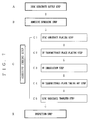
- the optical disc manufacturing apparatus comprises a substrate supply part for supplying upper and lower disc substrates to a portion where a next step is performed, an adhesive spread part for spreading an adhesive between the supplied both disc substrates and a UV curing part for curing the adhesive interposed between the bonded disc substrates.
- the optical disc manufacturing apparatus may have another operating part such as an inspection part in addition to the above three parts. If the inspection part is provided, an inspecting step is performed in this part.
- a reference numeral D2 depicts an upper disc substrate, D1 depicts a lower disc substrate, and D depicts bonded two substrates.
- a lower disc substrate D2 is placed on a turntable by a chuck from a stocker 102 where the lower disc substrate D2 is accumulated thereon in a disc supply step.
- an upper disc substrate D1 is placed on the turntable by a chuck from a stocker 101 where the upper disc substrate D1 are accumulated thereon in a disc supply step.
- Dust or static electricity is removed from the respective disc substrates D1 and D2 by a cleaner 103. While the lower disc substrate D2 stands ready, i.e., remains placed on the turntable, the upper disc substrate D1 alone is reversed by a reverser 104 and it is positioned in the manner that the face of the upper disc substrate D1 confronting the lower disc substrate D2 is directed downward.
- Two rotary tables 202 are disposed side by side for spreading an adhesive.
- the lower disc substrate D2 is placed on the rotary table 202 by a suction chuck 203 from the turntable in the supply step.
- the adhesive is coated on the lower disc substrate D2 like a doughnut shape from a resin dispenser 201.
- the adhesive is coated like a doughnut shape.
- the upper disc substrate D1 is placed on the lower disc substrate D2 on which the adhesive is coated using a suction chuck 203. Subsequently, the adhesive coated between the disc substrates D1 and D2 is uniformly expanded and spread when the rotary table 202 is rotated at high speed. The disc substrates D1 and D2 having the adhesive spread therebetween are moved to a next step using the suction chuck 203.
- the two disc substrates D1 and D2 which were subjected to the spreading step (hereinafter simply referred to as bonded substrate D) are placed on the turntable 1, as shown largely in Fig. 2, by the suction chuck 203 from the rotary tables 202.
- a special receiving table for transmitting light therethrough, described later, is disposed on the turntable 1. That is, a UV transmittance table 2, which is disposed on the turntable 1 so as to cover a circular through hole, described later, is used as the receiving table.
- the UV transmittance table 2 is disposed on the turntable 1 in the manner that the diameter of the UV transmission table 2 is engaged in the periphery of the through hole of the turntable 1.
- the UV transmittance table 2 is explained more in detail later with reference to Figs 4 and 5.
- the turntable 1 is rotated at prescribed angular interval and is positioned or centered to reach a taking up chuck 7.
- the taking up chuck 7 grips the UV transmittance plate 3 placed on a holding part 12 (see Fig. 5) provided on the middle of the turntable 1, then it places the UV transmittance plate 3 on the bonded disc substrate placed D on the UV transmittance table 2. More in detail, the UV transmittance plate 3 is moved toward the UV transmittance table 2 by the taking up chuck 7 and is placed on the bonded disc substrates D which is placed on the UV transmittance table 2 outside the UV transmittance plate 3.
- the UV transmittance plate 3 Since the UV transmittance plate 3 is placed on the bonded disc substrates D, the bonded disc substrates D does not warp and becomes stable. There are seven UV transmittance plates 3 on the turntable 1 corresponding to the seven UV transmittance tables 2 provided on the turntable 1 inside the portion where the UV transmittance tables 2 are disposed.
- the turntable 1 is turned at a prescribed angular interval and is centered to reach a UV irradiation position.
- the bonded disc substrates D are irradiated with UV by a UV irradiation unit 6 from the upper and lower sides thereof.
- the bonded disc substrates D are clamped by the UV transmittance plate 3 and the UV transmittance table 2 through which UV can pass, the bonded disc substrates D can be irradiated with UV from the upper and lower sides thereof without any hindrance.
- the bonded disc substrates D are irradiated with UV for two to three seconds, whereby the adhesive interposed between the disc substrates D1 and D2 is rapidly cured.
- the bonded disc substrates D are irradiated with UV from both sides thereof, the upper and lower surfaces of the bonded disc substrates D are uniformly irradiated with UV, namely, there does not occur any polarization of UV irradiation on both surfaces of the bonded disc substrates D, so that the bonded disc substrates D are prevented from warping, namely, there does not occur warp phenomenon. Further, since the bonded disc substrates D are clamped by the UV transmittance plate 3, the warp phenomenon is surely prevented.
- Fig. 3 is a schematic view of a UV irradiation unit.
- an irradiation port 62 of the UV irradiation unit 6 is disposed by way of a light path which is longer than a light source L positioned away from the turntable 1. That is, the UV irradiation unit 6 has the irradiation port 62 at the position away from the light source L by way of an arm part 61. The right path is closed or opened by a shutter S.
- the bonded disc substrates D placed on the UV transmittance table 2 over the turntable is not influenced by the heat from the light source L, namely, the bonded disc substrates D are not susceptible to the heat.
- the strength of UV which is irradiated vertically from the irradiation port 62 needs to be adaptable to the characteristics of the respective disc substrates D1 and D2, and the strength of the UV from the respective UV irradiation sources may be adjusted in such a sense.
- These upper and lower hoods 63 and 64 are extended from the upper and lower irradiation ports 62 and reach the upper surface of a reflecting mirror described later in the manner of covering the bonded disc substrates D. Further, gas is generated when the adhesive of the bonded disc substrates D are cured by the irradiation of the UV, and hence a suction part 63A is provided on the upper hood 63 extended from the upper irradiation port 62.
- the turntable 1 Upon completion of the irradiation with UV, the turntable 1 is turned at a prescribed angular interval and is centered to reach a taking out chuck 8 of the UV transmittance plate 3. Then, the UV transmittance plate 3 placed on the bonded disc substrates D (which is placed on the UV transmittance table 2) is taken out by the taking out chuck 8. Thus taken out UV transmittance plate 3 is returned to the holding part 12 (see Fig. 5) on which the UV transmittance plate 3, which is provided inside the turntable 1, is placed.
- the bonded disc substrates which are taken out from the UV transmittance plate 3 becomes an optical disc when the adhesive is cured.
- the optical disc is separated from the turntable 1, and is transferred to another position by a transfer chuck 9, for example, transferred to a part where an inspection step is performed.
- the inspection step it is decided whether or not the optical disc has sufficient quality conforming to standards.
- the inspection items are differentiated depending on standards. For example, the degree of tilting of the optical disc is inspected by a tilt measuring unit X1. If the optical disc is up to the standard, it is placed and accumulated on a standard stocker 10.
- optical disc is completed by the steps set forth above.
- Fig. 6 is a view schematically showing the state where the bonded disc substrates D are placed on the turntable 1 in the adhesive curing step, and the curing of the adhesive is completed.
- the reflecting mirror is omitted.
- Fig. 6 (1) shows that the bonded disc substrates D (disc substrates D1 and D2) is taken out from the rotary table 202 upon completion of the adhesive spreading step.
- the bonded disc substrates D are placed on the UV transmittance table 2 over the turntable 1, then as shown in Fig. 6 (3), the UV transmittance plate 3 is placed on the bonded disc substrates D. Thereafter, as shown in Fig. 6 (4), the bonded disc substrates D are irradiated with UV from the upper and lower sides thereof so that the adhesive (UV curing resin) is cured. Subsequently, as shown in Fig. 6 (5), the UV transmittance plate 3 is taken out from the bonded disc substrates D. Finally, as shown in Fig. 6 (6), the bonded disc substrates D are taken out from the UV transmittance table 2.
- Fig. 4 shows the UV transmittance table 2 and its neighborhood in the UV irradiation step.
- the upper hood 63 is denoted by two dotted one solid line, the position of the upper hood 63 is shown, for reference, using Fig. 4, and hence the UV irradiation unit i.e., hood is not disposed in the position where a moving unit 500 is disposed.
- UV transmittance table 2 is disposed so as to cover or close each through hole 11 of the turntable 1.
- the UV transmittance table 2 comprises a large diameter portion and a small diameter portion wherein the UV transmittance table 2 is supported by the turntable 1 when the large diameter portion is engaged in the turntable 1.
- the bonded disc substrates D are placed on the UV transmittance table 2, and the UV transmittance plate 3 is placed on the bonded disc substrates D.
- the UV transmittance plate 3 is provided for clamping the bonded disc substrates D between itself and the UV transmittance table 2, and the diameter of the UV transmittance plate 3 is preferably slightly smaller than that of the bonded disc substrates D.
- the small diameter portion of the UV transmittance table 2 is also preferably slightly smaller than that of the bonded disc substrates D.
- a cylindrical reflecting mirror 4 is attached to the turntable 1 so as to press the UV transmittance table 2 from the upper side thereof.
- the cylindrical reflecting mirror 4 is provided in the aid of irradiation of UV so that the ends of the bonded disc substrates D are surely irradiated with the UV in the UV irradiation step.
- the UV transmittance table 2 and UV transmittance plate 3 may be formed of a plate made of a material through which UV can be sufficiently passes, for example, a heat-resistant glass plate such as quartz glass, PYREX (trademark).
- the UV transmittance table 2 is bored at the center thereof to define a hole, and a boss 5 is fixed to this central hole.
- the boss 5 positions or centers three elements, namely, the UV transmittance table 2, UV transmittance plate 3, and bonded disc substrates D, and particularly, the boss 5 centers the bonded disc substrates D, and the diameter of the boss 5 is can be increased.
- the boss 5 has a plurality of pawls 51 and it is inserted into the central holes of the UV transmittance plate 3 and bonded disc substrates D wherein the respective pawls 51 are moved outwardly or radially to expand the inner peripheral surfaces of the central holes of the UV transmittance plate 3 and the bonded disc substrates D outward. Accordingly, the UV transmittance table 2, UV transmittance plate 3 and bonded disc substrates D can be surely positioned or centered.
- the outward movement of the pawls 51 of the boss 5 is performed when an center pin 52 pushes up the pawls 51 from the inner side thereof.
- the downward movement of the center pin 52 can be performed when a hook 502 of the moving unit 500 fixed to a floor or a fixed table pulls down a washer 52A of the center pin 52.
- the upward returning of the center pin 52 can be performed by a spring which resiliently pushing the center pin 52 upward.
- a plurality of moving units 500 are disposed respective portions under the turntable such as disc substrate placing part, UV transmittance plate placing part, UV transmittance plate taking out part, disc substrate transfer part.
- the diameter of the boss 5 can be sufficiently decreased by pressing the pawls 51 even if the diameter of the boss 5 is not decreased when the bonded disc substrates D are placed or taken out from the boss 5 because the UV transmittance plate is strong.
- the moving unit 500 may be disposed only on the disc substrate placing part and the disc substrate taking out part.
- the boss 5 fixed to the UV transmittance table 2 by the rotary motion of the turntable 1 is connected to the moving units 500 which are respectively disposed on respective parts under the turntable as set forth above. That is, the center pin 52 of the boss 5 passes through a guide gap 501 in a space of the moving unit and moves perpendicularly relative to the paper surface, then it is disposed in the moving unit 500.
- Fig. 5 shows the UV transmittance table 2 and its neighborhood in a step of placing the UV transmittance plate 3 on the bonded disc substrates D.
- the center pin 52 of the boss 5 move inward so that the diameter of the boss 5 is decreased. Accordingly, the UV transmittance plate 3 is placed on the bonded disc substrates D without any hindrance. Thereafter, the center pin 52 rises upward, and hence the diameter of the boss 5 is increased to perform the positioning or centering.
- the moving unit 500 operates to increase or decrease the diameter the boss 5 in the step of disc substrate placing step, UV transmittance plate placing step, UV transmittance plate taking out step, disc substrate transfer step, etc.
- the present invention is not limited to the embodiment set forth above but it can be modified variously without departing the spirit of the invention.
- the shape and the number of dispositions of the UV irradiation unit can be freely designed.
- the shape of the UV transmittance plate is not limited to the circular one but it may be of any shape if the optical disc can be clamped by at least two UV transmittance plates.
- the present invention has the construction set forth above, the warp phenomenon of the optical disc can be prevented and the curing of the optical disc can be efficiently performed.
Landscapes
- Engineering & Computer Science (AREA)
- Mechanical Engineering (AREA)
- Physics & Mathematics (AREA)
- Electromagnetism (AREA)
- Health & Medical Sciences (AREA)
- Toxicology (AREA)
- Chemical & Material Sciences (AREA)
- Chemical Kinetics & Catalysis (AREA)
- General Chemical & Material Sciences (AREA)
- Manufacturing Optical Record Carriers (AREA)
Applications Claiming Priority (2)
| Application Number | Priority Date | Filing Date | Title |
|---|---|---|---|
| JP16926398A JP3280313B2 (ja) | 1998-06-01 | 1998-06-01 | 光ディスクの製造方法 |
| JP16926398 | 1998-06-01 |
Publications (2)
| Publication Number | Publication Date |
|---|---|
| EP0962301A2 true EP0962301A2 (fr) | 1999-12-08 |
| EP0962301A3 EP0962301A3 (fr) | 2002-02-06 |
Family
ID=15883277
Family Applications (1)
| Application Number | Title | Priority Date | Filing Date |
|---|---|---|---|
| EP99110589A Withdrawn EP0962301A3 (fr) | 1998-06-01 | 1999-06-01 | Méthode de fabrication de disques optiques |
Country Status (3)
| Country | Link |
|---|---|
| US (1) | US6224702B1 (fr) |
| EP (1) | EP0962301A3 (fr) |
| JP (1) | JP3280313B2 (fr) |
Cited By (1)
| Publication number | Priority date | Publication date | Assignee | Title |
|---|---|---|---|---|
| CN105499082A (zh) * | 2016-01-26 | 2016-04-20 | 苏州富强科技有限公司 | 用于点胶装置的产品固定机构 |
Families Citing this family (12)
| Publication number | Priority date | Publication date | Assignee | Title |
|---|---|---|---|---|
| CN100334635C (zh) * | 2000-04-25 | 2007-08-29 | 松下电器产业株式会社 | 光盘制造方法 |
| JP3559535B2 (ja) * | 2001-05-16 | 2004-09-02 | 北野エンジニアリング株式会社 | 光ディスク接着剤硬化装置 |
| JP2003272237A (ja) * | 2002-03-20 | 2003-09-26 | Sony Corp | 光学記録媒体およびその製造方法 |
| US20040134603A1 (en) | 2002-07-18 | 2004-07-15 | Hideo Kobayashi | Method and apparatus for curing adhesive between substrates, and disc substrate bonding apparatus |
| TW587825U (en) * | 2003-03-11 | 2004-05-11 | Automation Design & Manufactur | Compact disk manufacturing machine |
| KR20050090310A (ko) * | 2004-03-08 | 2005-09-13 | 가부시키가이샤 기타노 | 광 디스크의 자외선 조사장치 및 광 디스크로의 자외선조사방법 |
| US7314536B2 (en) * | 2004-10-14 | 2008-01-01 | Sony Corporation | Disc pairing in optical disc replication |
| WO2006093495A1 (fr) * | 2005-03-02 | 2006-09-08 | Thomson Licensing | Appareil et procédé permettant d’améliorer le contrôle du faux-rond du trou central lors de la fabrication d’un disque optique |
| US7073554B1 (en) * | 2005-05-20 | 2006-07-11 | Guann Way Technologies Co., Ltd. | Integration device for compact disk |
| US7740729B1 (en) * | 2007-02-01 | 2010-06-22 | Dongguan Anwell Digital Machinery Co., Ltd. | Method and system for controlling the eccentricity of bonded multiple optical discs |
| JP4746003B2 (ja) * | 2007-05-07 | 2011-08-10 | リンテック株式会社 | 移載装置及び移載方法 |
| US10158480B1 (en) | 2015-03-16 | 2018-12-18 | Winklevoss Ip, Llc | Autonomous devices |
Citations (1)
| Publication number | Priority date | Publication date | Assignee | Title |
|---|---|---|---|---|
| US5779855A (en) | 1995-08-30 | 1998-07-14 | Kitano Engineering Co., Ltd. | Apparatus for curing an optical disc |
Family Cites Families (20)
| Publication number | Priority date | Publication date | Assignee | Title |
|---|---|---|---|---|
| US4877475A (en) | 1984-11-01 | 1989-10-31 | Matsushita Electric Industrial Co., Ltd. | Method for producing information storage disk |
| US5364256A (en) | 1986-01-28 | 1994-11-15 | Ophthalmic Research Group International, Inc. | Apparatus for the production of plastic lenses |
| JPS6327577A (ja) * | 1986-07-21 | 1988-02-05 | Ushio Inc | 光接着方法及び装置 |
| NL8702493A (nl) | 1986-10-31 | 1988-05-16 | Seiko Epson Corp | Optisch opnamemedium en werkwijze voor het vervaardigen daarvan. |
| JPH07119389B2 (ja) * | 1987-08-17 | 1995-12-20 | ウシオ電機株式会社 | 光接着装置 |
| JPH0626823B2 (ja) | 1987-10-15 | 1994-04-13 | パイオニア株式会社 | 光ディスク製造装置 |
| EP0408763B1 (fr) | 1989-01-11 | 1997-06-04 | Seiko Epson Corporation | Disque optique et procede de production |
| JPH0457234A (ja) * | 1990-06-21 | 1992-02-25 | Japan Steel Works Ltd:The | 光ディスク基板の心合わせ方法及び装置 |
| US5597519A (en) | 1994-06-10 | 1997-01-28 | Johnson & Johnson Vision Products, Inc. | Ultraviolet cycling oven for polymerization of contact lenses |
| US5681634A (en) | 1995-02-15 | 1997-10-28 | Matsushita Electric Industrial Co., Ltd. | Optical information medium, and method and apparatus for fabricating the same |
| JP3096242B2 (ja) * | 1995-08-30 | 2000-10-10 | 日本政策投資銀行 | 光ディスクの硬化装置 |
| JP3635588B2 (ja) | 1995-09-19 | 2005-04-06 | パイオニア株式会社 | 光ディスクの製造方法及び多層光ディスク |
| JP3018276B2 (ja) * | 1996-01-12 | 2000-03-13 | 株式会社ホロン | 光学式記録情報媒体の貼り合わせ方法及びその装置 |
| US5938891A (en) * | 1996-02-27 | 1999-08-17 | Origin Electric Company, Limited | Disk bonding system |
| JPH09297941A (ja) * | 1996-05-08 | 1997-11-18 | Matsushita Electric Ind Co Ltd | 光情報媒体の製造方法および製造装置 |
| CA2206613C (fr) | 1996-05-31 | 2000-12-19 | Ushiodenki Kabushiki Kaisha | Processus et dispositif servant a souder des disques les uns aux autres |
| EP0833315B1 (fr) * | 1996-07-31 | 2004-11-24 | Kitano Engineering Co., Ltd. | Procédé pour la correction du non-alignement d'un disque d'information |
| JP3270688B2 (ja) * | 1996-09-03 | 2002-04-02 | ウシオ電機株式会社 | ディスクの貼り合わせ装置 |
| JP3414949B2 (ja) * | 1996-10-29 | 2003-06-09 | ウシオ電機株式会社 | 紫外線硬化装置 |
| JP2001505349A (ja) * | 1997-05-27 | 2001-04-17 | コーニンクレッカ フィリップス エレクトロニクス エヌ ヴィ | 情報担体の2層の間の接着材を硬化させる装置 |
-
1998
- 1998-06-01 JP JP16926398A patent/JP3280313B2/ja not_active Expired - Fee Related
-
1999
- 1999-05-28 US US09/322,489 patent/US6224702B1/en not_active Expired - Fee Related
- 1999-06-01 EP EP99110589A patent/EP0962301A3/fr not_active Withdrawn
Patent Citations (1)
| Publication number | Priority date | Publication date | Assignee | Title |
|---|---|---|---|---|
| US5779855A (en) | 1995-08-30 | 1998-07-14 | Kitano Engineering Co., Ltd. | Apparatus for curing an optical disc |
Cited By (1)
| Publication number | Priority date | Publication date | Assignee | Title |
|---|---|---|---|---|
| CN105499082A (zh) * | 2016-01-26 | 2016-04-20 | 苏州富强科技有限公司 | 用于点胶装置的产品固定机构 |
Also Published As
| Publication number | Publication date |
|---|---|
| JP3280313B2 (ja) | 2002-05-13 |
| JPH11345433A (ja) | 1999-12-14 |
| EP0962301A3 (fr) | 2002-02-06 |
| US6224702B1 (en) | 2001-05-01 |
Similar Documents
| Publication | Publication Date | Title |
|---|---|---|
| US6224702B1 (en) | Method of manufacturing optical discs | |
| EP0833315B1 (fr) | Procédé pour la correction du non-alignement d'un disque d'information | |
| US6013145A (en) | Method of curing an optical disc | |
| US5938891A (en) | Disk bonding system | |
| EP1298653B1 (fr) | Dispositif et procede de production d'un disque optique | |
| US6170172B1 (en) | Device and method for curing an adhesive between two layers of an information carrier | |
| US6355129B1 (en) | System and method for thermally manipulating a combination of a top and bottom substrate before a curing operation | |
| JP2941196B2 (ja) | 光ディスクの製造方法および製造装置 | |
| TW448444B (en) | Method and apparatus for bonding optical disk substrate | |
| KR100328602B1 (ko) | 기판 건조용 장치 | |
| JPH09128823A (ja) | 光ディスクの硬化方法及びその装置 | |
| US6503423B1 (en) | Method of and apparatus for curing an optical disc | |
| US6511616B1 (en) | System and method for curing a resin disposed between a top and bottom substrate with thermal management | |
| JP3414950B2 (ja) | 紫外線硬化装置 | |
| US6430803B1 (en) | Method for maintaining concentricity of a combination of a top and bottom substrate during the assembly of a bonded storage disk | |
| US6500297B1 (en) | Method of forming bonded storage disks with low power light assembly | |
| EP1164009A2 (fr) | Système et procédé pour réaliser le durcissement d'une resine placée entre un substrat supérieur et un substrat inférieur avec gestion de l'energie thermique | |
| EP1030771B1 (fr) | Systeme et procede pour repartir une resine appliquee entre un substrat superieur et un substrat inferieur | |
| EP1031147A1 (fr) | Systeme et procede de formation de disques colles de stockage d'informations avec un ensemble emettant une lumiere de faible puissance | |
| EP1030772B1 (fr) | Systeme et procede pour appliquer une resine entre les substrats d'un disque support d'informations contrecolle | |
| EP1030780B1 (fr) | Systeme et procede pour realiser le durcissement d'une resine placee entre un substrat superieur et un substrat inferieur avec gestion de l'energie thermique | |
| US6214412B1 (en) | System and method for distributing a resin disposed between a top substrate and a bottom substrate | |
| EP1164004A2 (fr) | Système et procédé pour appliquer une résine entre les substrats d'un disque support d'informations contrecollé | |
| EP1030814B1 (fr) | Systeme et procede destines a maintenir la concentricite d'un substrat superieur et un substrat inferieur combines pendant l'assemblage d'un disque colle de stockage d'informations | |
| WO1999024976A1 (fr) | Systeme et procede ameliores de durcissement d'une resine dans un disque colle de stockage d'informations |
Legal Events
| Date | Code | Title | Description |
|---|---|---|---|
| PUAI | Public reference made under article 153(3) epc to a published international application that has entered the european phase |
Free format text: ORIGINAL CODE: 0009012 |
|
| AK | Designated contracting states |
Kind code of ref document: A2 Designated state(s): AT BE CH CY DE DK ES FI FR GB GR IE IT LI LU MC NL PT SE Kind code of ref document: A2 Designated state(s): DE FR GB NL |
|
| AX | Request for extension of the european patent |
Free format text: AL;LT;LV;MK;RO;SI |
|
| PUAL | Search report despatched |
Free format text: ORIGINAL CODE: 0009013 |
|
| AK | Designated contracting states |
Kind code of ref document: A3 Designated state(s): AT BE CH CY DE DK ES FI FR GB GR IE IT LI LU MC NL PT SE |
|
| AX | Request for extension of the european patent |
Free format text: AL;LT;LV;MK;RO;SI |
|
| RIC1 | Information provided on ipc code assigned before grant |
Free format text: 7G 11B 7/26 A, 7B 32B 31/12 B, 7B 29C 65/52 B |
|
| AKX | Designation fees paid |
Free format text: DE FR GB NL |
|
| STAA | Information on the status of an ep patent application or granted ep patent |
Free format text: STATUS: THE APPLICATION IS DEEMED TO BE WITHDRAWN |
|
| 18D | Application deemed to be withdrawn |
Effective date: 20020807 |