EP0962288A2 - Schild für die Werkzeugnase eines verbrennungskraftbetriebenen Werkzeugs - Google Patents
Schild für die Werkzeugnase eines verbrennungskraftbetriebenen Werkzeugs Download PDFInfo
- Publication number
- EP0962288A2 EP0962288A2 EP99401334A EP99401334A EP0962288A2 EP 0962288 A2 EP0962288 A2 EP 0962288A2 EP 99401334 A EP99401334 A EP 99401334A EP 99401334 A EP99401334 A EP 99401334A EP 0962288 A2 EP0962288 A2 EP 0962288A2
- Authority
- EP
- European Patent Office
- Prior art keywords
- tool
- nosepiece
- workpiece
- power source
- combustion
- Prior art date
- Legal status (The legal status is an assumption and is not a legal conclusion. Google has not performed a legal analysis and makes no representation as to the accuracy of the status listed.)
- Withdrawn
Links
- 238000002485 combustion reaction Methods 0.000 title claims abstract description 43
- 230000001681 protective effect Effects 0.000 abstract description 2
- 239000000446 fuel Substances 0.000 description 14
- 230000002708 enhancing effect Effects 0.000 description 2
- 239000007789 gas Substances 0.000 description 2
- 230000013011 mating Effects 0.000 description 2
- 230000007246 mechanism Effects 0.000 description 2
- 230000002000 scavenging effect Effects 0.000 description 2
- 238000007789 sealing Methods 0.000 description 2
- 239000004215 Carbon black (E152) Substances 0.000 description 1
- 230000001133 acceleration Effects 0.000 description 1
- 230000009471 action Effects 0.000 description 1
- 238000013459 approach Methods 0.000 description 1
- 239000006227 byproduct Substances 0.000 description 1
- 239000010960 cold rolled steel Substances 0.000 description 1
- 238000004891 communication Methods 0.000 description 1
- 238000010276 construction Methods 0.000 description 1
- 238000001816 cooling Methods 0.000 description 1
- 238000010304 firing Methods 0.000 description 1
- 239000012530 fluid Substances 0.000 description 1
- 239000002737 fuel gas Substances 0.000 description 1
- 229930195733 hydrocarbon Natural products 0.000 description 1
- 150000002430 hydrocarbons Chemical class 0.000 description 1
- 239000007788 liquid Substances 0.000 description 1
- 239000000463 material Substances 0.000 description 1
- 239000002184 metal Substances 0.000 description 1
- 229910052751 metal Inorganic materials 0.000 description 1
- 150000002739 metals Chemical class 0.000 description 1
- 238000002156 mixing Methods 0.000 description 1
- 239000000203 mixture Substances 0.000 description 1
- 238000012986 modification Methods 0.000 description 1
- 230000004048 modification Effects 0.000 description 1
- 230000035515 penetration Effects 0.000 description 1
- 230000002093 peripheral effect Effects 0.000 description 1
- 238000003825 pressing Methods 0.000 description 1
- VBUBYMVULIMEHR-UHFFFAOYSA-N propa-1,2-diene;prop-1-yne Chemical compound CC#C.C=C=C VBUBYMVULIMEHR-UHFFFAOYSA-N 0.000 description 1
- 239000003380 propellant Substances 0.000 description 1
- 230000004044 response Effects 0.000 description 1
- 239000000758 substrate Substances 0.000 description 1
Images


Classifications
-
- B—PERFORMING OPERATIONS; TRANSPORTING
- B25—HAND TOOLS; PORTABLE POWER-DRIVEN TOOLS; MANIPULATORS
- B25C—HAND-HELD NAILING OR STAPLING TOOLS; MANUALLY OPERATED PORTABLE STAPLING TOOLS
- B25C1/00—Hand-held nailing tools; Nail feeding devices
- B25C1/008—Safety devices
-
- B—PERFORMING OPERATIONS; TRANSPORTING
- B25—HAND TOOLS; PORTABLE POWER-DRIVEN TOOLS; MANIPULATORS
- B25C—HAND-HELD NAILING OR STAPLING TOOLS; MANUALLY OPERATED PORTABLE STAPLING TOOLS
- B25C1/00—Hand-held nailing tools; Nail feeding devices
- B25C1/08—Hand-held nailing tools; Nail feeding devices operated by combustion pressure
Definitions
- the present invention relates generally to portable combustion powered fastener driving tools, and specifically to a shield to protect a workpiece-contacting element of a nosepiece of such tools.
- Such tools incorporate a generally pistol-shaped tool housing enclosing a small internal combustion engine.
- the engine is powered by a canister of pressurized fuel gas, also called a fuel cell.
- a battery-powered electronic power distribution unit produces the spark for ignition, and a fan located in the combustion chamber provides for both an efficient combustion within the chamber, and facilitates scavenging, including the exhaust of combustion by-products.
- the engine includes a reciprocating piston with an elongated, rigid driver rod disposed within a cylinder body.
- a valve sleeve is axially reciprocal about the cylinder and, through a linkage, moves to close the combustion chamber when a work contact element at the end of the linkage is pressed against a workpiece. This pressing action also triggers a fuel metering valve to introduce a specified volume of fuel into the closed combustion chamber.
- the piston and driver rod Upon the pulling of a trigger switch, which causes the ignition of a charge of gas in the combustion chamber of the engine, the piston and driver rod are shot downward to impact a positioned fastener and drive it into the workpiece. The piston then returns to its original, or "ready” position, through differential gas pressures within the cylinder. Fasteners are fed magazine-style into the nosepiece, where they are held in a properly positioned orientation for receiving the impact of the driver rod.
- the combustion in the chamber Upon ignition of the combustible fuel/air mixture, the combustion in the chamber causes the acceleration of the piston/driver rod assembly and the penetration of the fastener into the workpiece if the fastener is present.
- the nosepiece ofthe tool includes a pair of upper and lower guide members for guiding the driver rod towards the uppermost nail of a nail strip. Fasteners are guided to the workpiece by a workpiece end of the nosepiece.
- a disadvantage of conventional combustion powered tools of this type is that the nosepiece is not enclosed by the housing. Therefore, in some applications, damage can occur to the nosepiece if, for example, a workman dropped the tool. Also, the nosepiece is adjustable to vary the depth that the fastener is driven into the workpiece. These adjustments are typically made by the operator of the tool. Thus, there is a need to protect the nosepiece, and the corresponding components of the nosepiece, from external forces. There is also a need to protect the depth adjustment from inadvertent impact or interference by the operator or others.
- the present combustion powered tool for driving fasteners featuring a shield which is fixed to the tool housing and is configured to encompass the nosepiece without impairing its operation. Access openings are provided in the shield to provide access to the fastener driving depth adjustment mechanism.
- the present invention provides a combustion powered tool for driving fasteners having a housing to house a main chamber.
- a power source having a combustion end and a lower end.
- the combustion end of the power source drives a rod.
- Fasteners are sequentially fed to the rod for engagement with the rod.
- a nosepiece having a tool end, and a workpiece end opposite the tool end.
- the nosepiece is configured for receiving the rod and for guiding the rod toward a workpiece.
- a protective shield envelops the nosepiece.
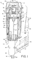
- a combustion-powered tool of the type suitable for use with the present invention is generally designated 10.
- the tool 10 has a housing 12 including a main power source chamber 14 dimensioned to enclose a self-contained internal combustion power source 16, a fuel cell chamber 18 (shown in phantom) generally parallel with and adjacent the main chamber 14, and a handle portion 20 extending from one side of the fuel cell chamber and opposite the main chamber.
- a fastener magazine 22 is positioned below the handle portion and extends to a nosepiece 26 depending from a lower end 28 of the main chamber 14.
- the magazine 22 accommodates a strip of nails, as shown, but alternatively may accommodate a coil of nails as shown in U.S. Patent No. 5,558,264.
- a battery (not shown) is provided for providing electrical power to the tool 10, and is releasably housed in a tubular compartment (not shown) located in the handle portion 20.
- lower and upper are used to refer to the tool 10 in its operational orientation as depicted in FIGs. 1 and 2, and “front” is used to refer to the left side of the tool 10 as depicted in FIGs. 1 and 2; however it will be understood that this invention may be used in a variety of orientations depending on the application.
- a combustion end 30 Opposite the lower end 28 of the main chamber is a combustion end 30, which is provided with a plurality of air intake vents 32.
- a pressurized liquid hydrocarbon fuel such as MAPP
- a fuel cell not shown
- a propellant as is known in the art.
- a fluid communication is established between the fuel cell and the valve.
- a mechanically operated valve is used, such as that currently available in an IMPULSE® tool sold by ITW-Paslode.
- an electro-magnetic solenoid-type fuel metering valve may be used.
- a cylinder head 34 is disposed at the combustion end 30 of the main chamber, and defines an upper end of a combustion chamber 36, also located at the upper end of the chamber, and provides a mounting point for a head switch 38 (shown in phantom), a spark plug 40, an electric fan motor 42, and a sealing O-ring 44.
- a main or combustion chamber fan 46 is attached to an armature or power shaft 48 of the motor 42 at a first end 50 of the armature. Located within the combustion chamber 36 to axially rotate, the fan 46 thus enhances the combustion process by mixing the fuel and air, and also facilitates cooling and scavenging.
- the fan motor 42 is controlled by the head switch 38, as disclosed in more detail in the prior patents incorporated by reference.
- the fan 46 serves as a main air flow enhancing device for enhancing the flow of air within the combustion chamber 36.
- a generally cylindrical, reciprocating valve member or valve sleeve 52 is moved within the main chamber 14 by a workpiece-contacting element 54 slidably mounted on an outside of the nosepiece 26 using a linkage 56.
- Sidewalls of the combustion chamber 36 are defined by the valve member 52, the upper end of which sealingly engages the O-ring 44 to seal the upper end of the combustion chamber.
- a lower portion 58 of the valve member 52 circumscribes a generally cylindrical cylinder body 60.
- An upper end of the cylinder body 60 is provided with an exterior O-ring 62 which engages a corresponding portion 64 of the valve member 52 to seal a lower end of the combustion chamber 36.
- a piston 66 Within the cylinder body 60 is reciprocally disposed a piston 66 to which is attached a rigid, elongated driver rod 67 used to drive fasteners 68 (shown hidden in FIG. 1), transported from the magazine 22 and suitably positioned in the nosepiece 26, into a workpiece.
- a trigger 69 As a trigger 69 is pulled, a signal is generated from the central electrical distribution and control unit (not shown) to cause a discharge at a spark gap of a spark plug (not shown), which ignites fuel which has been injected into the combustion chamber 36 and vaporized or fragmented by the fan 46.
- the piston 66 is driven toward a lower end of the cylinder 60.
- the driver rod 67 will be guided into the nosepiece 26 and impact a fastener 68 held above a workpiece by the nosepiece. Impact of the driver rod 67 drives the fastener into a workpiece or substrate.
- a lower end of the cylinder body 60 defines a seat 70 for a bumper 71 which defines the lower limit of travel of the piston 66.
- a piston stop ring 72 is affixed to limit the upward travel of the piston 66.
- a shield 73 of a preferred embodiment of the present invention protects the nosepiece 26 with its corresponding components.
- a retaining ring 75 fixed to the lower end 28 of the power source 16 by at least one screw 76 or other threaded fastener.
- the nosepiece 26 further includes a pair of front and rear guide members 78 and 79 disposed below the retaining ring 75.
- the rear guide member 79 is actually a front surface of the magazine 22. Mating surfaces (not shown) of the front and rear guide members 78 and 79 are formed with semi-circular grooves.
- the semi-circular grooves of the mating surfaces form a guide passage (not shown) having a cross sectional shape corresponding to the shape of, and coaxial with, the driving rod 67 and fasteners 68 for guiding the driving rod and the fasteners.
- the nosepiece 26 also includes the workpiece-contacting element 54 which extends generally vertically in spaced, generally parallel relationship to a front surface 81 of the front guide member 78.
- a lower portion 82 of the linkage 56 is fixed to the workpiece-contacting element 54 by at least one and preferably two depth of drive adjustment screws 84. The screws 84 pass through a vertically extending slot 86 in the workpiece contacting element 54.
- the shield 73 has a top end 88, a bottom end 90, and a generally tubular shape configured to circumscribe the nosepiece 26.
- the shield 73 is preferably of durable construction, and can be manufactured, for example, from 16-gauge 1050 cold rolled steel. The use of other equivalent engineered materials or metals is also contemplated.
- the retaining ring 75 is fastened to the top end 88 of the shield 73, and is configured for attachment to the lower end 28 of the power source 16. In length, the shield 73 is configured so that when the nosepiece 26 is pushed against the workpiece, and the workpiece contacting element 54 is completely retracted, the bottom end 90 of the shield 73 occupies a position substantially flush with the workpiece.
- a longitudinal peripheral wall 92 of the shield 73 is inclined from the top end 88 to the bottom end 90 to form a generally hollow inverted conical shape. This shape accommodates the nosepiece 26, the movement of the workpiece-contacting element 54, the linkage portion 82, and the screws 84, yet provides good visibility of the workpiece.
- the retaining ring 75 which is a previously existing component of the tool 10, has a generally circular shape with notches 75a defined therein to accommodate parts of the nosepiece 26, and the driver rod 67. Additionally, the retaining ring 75 contains a hole 91 for accepting the screw 76 to attach the retaining ring 75 to the lower end 28 of the power source 16.
- the shield 73 is preferably welded along the top end 88 to at least 75% of a perimeter of the retaining ring 75.
- the shield 73 could be stamped or molded in one piece, or molded into a die cast housing which could be part of the main body.
- the shield 73 is constructed and arranged to cover at least three of the sides, the fourth side being abuttingly engaged by the fastener magazine 22.
- Rearward facing edges 92a, 92b of the wall 92 define a space for accommodating the magazine 22.
- At least one access opening 94 (preferably three are provided) in the shield 73 is provided for access to the drive adjustment screws 84 on the nosepiece 26.
- Each access opening 94 is constructed and arranged so that only one of the drive adjustment screws 84 can be accessed at a time. For example, one of the screws 84 can be accessed while the nosepiece 26 is in an unretracted position, and the other can be accessed when the nosepiece 26 is retracted, as occurs when the tool is pressed against the workpiece.
- Multiple access openings 94 are provided to allow the same nosepiece shield 73 to be used on a variety of tools 10.
- the shield 73 is constructed to define a cavity 95 between the nosepiece 26 and the shield 73 to allow the drive adjustment.
- FIG. 6 shows an alternative embodiment of the present shield which is generally designated 73a. Shared components between the shields 73 and 73a are indicated with the identical reference numerals.
- the shield 73a is designed for use on a smaller combustion type tool used for driving fasteners 68 into more delicate workpieces such as in trim work.
- An opening 96 is provided in the shield 73a for access to a depth adjustment of the nosepiece 26.
- a notch 98 in the shield 73a allows access to a screw 99 (shown in FIG. 1) for the fastener magazine 22.
- the shield 73a has a generally curved lower edge 100 which allows the tool to be angled relative to the workpiece for application when the fastener 68 needs to be driven on an angle. It is contemplated that other such openings and notches 94, 96, 98, may be added when necessary to fit combustion powered tools of various configurations.
Landscapes
- Engineering & Computer Science (AREA)
- Mechanical Engineering (AREA)
- Chemical & Material Sciences (AREA)
- Combustion & Propulsion (AREA)
- Portable Nailing Machines And Staplers (AREA)
- Ignition Installations For Internal Combustion Engines (AREA)
Applications Claiming Priority (2)
| Application Number | Priority Date | Filing Date | Title |
|---|---|---|---|
| US89902 | 1979-10-31 | ||
| US09/089,902 US5988477A (en) | 1998-06-03 | 1998-06-03 | Nosepiece shield for combustion powered tool |
Publications (1)
| Publication Number | Publication Date |
|---|---|
| EP0962288A2 true EP0962288A2 (de) | 1999-12-08 |
Family
ID=22220150
Family Applications (1)
| Application Number | Title | Priority Date | Filing Date |
|---|---|---|---|
| EP99401334A Withdrawn EP0962288A2 (de) | 1998-06-03 | 1999-06-03 | Schild für die Werkzeugnase eines verbrennungskraftbetriebenen Werkzeugs |
Country Status (6)
| Country | Link |
|---|---|
| US (1) | US5988477A (de) |
| EP (1) | EP0962288A2 (de) |
| JP (2) | JP3652923B2 (de) |
| AU (1) | AU714594B1 (de) |
| CA (1) | CA2273465C (de) |
| NZ (1) | NZ336061A (de) |
Cited By (2)
| Publication number | Priority date | Publication date | Assignee | Title |
|---|---|---|---|---|
| FR2814693A1 (fr) * | 2000-09-29 | 2002-04-05 | Hilti Ag | Outil de scellement |
| EP1616669A1 (de) * | 2004-07-14 | 2006-01-18 | Hitachi Koki Co., Ltd. | Eintriebwerkzeug für Befestigungsmittel |
Families Citing this family (20)
| Publication number | Priority date | Publication date | Assignee | Title |
|---|---|---|---|---|
| US6164510A (en) * | 1998-06-03 | 2000-12-26 | Illinois Tool Works Inc. | Nosepiece shield for combustion powered tool |
| DE10160575C1 (de) * | 2001-12-10 | 2003-06-18 | Hilti Ag | Setzgerät |
| US6708821B2 (en) | 2002-08-21 | 2004-03-23 | Illinois Tool Works Inc. | Fastener collation strip and debris exhaust mechanism |
| US7040520B2 (en) * | 2002-09-12 | 2006-05-09 | Illinois Tool Works Inc. | Fan motor suspension mount for a combustion-powered tool |
| US6695192B1 (en) * | 2002-09-30 | 2004-02-24 | Illinois Tool Works Inc. | Adjustable depth control for fastener driving tool |
| US6964553B2 (en) * | 2003-05-23 | 2005-11-15 | Illinois Tool Works Inc. | Port for a fan chamber |
| FR2855444B1 (fr) * | 2003-06-02 | 2005-08-05 | Prospection & Inventions | Appareil a chambre de combustion a fonctionnement a gaz |
| JP4239731B2 (ja) * | 2003-07-04 | 2009-03-18 | マックス株式会社 | 動力駆動釘打機のコンタクト機構 |
| FR2858261B1 (fr) * | 2003-07-29 | 2005-09-09 | Prospection & Inventions | Appareil a fonctionnement a gaz d'entrainement d'un element par piston |
| DE102006000025A1 (de) * | 2006-01-25 | 2007-07-26 | Hilti Ag | Setzgerät |
| US20080078799A1 (en) * | 2006-10-03 | 2008-04-03 | Wan-Fu Wen | Nail Gun with Electric Power Generating Unit |
| US8152038B2 (en) * | 2007-03-16 | 2012-04-10 | Illinois Tool Works Inc. | Nose assembly for a fastener driving tool |
| US8220686B2 (en) * | 2007-07-17 | 2012-07-17 | Illinois Tool Works Inc. | Actuator pin guide for a fastener driving tool |
| JP5067110B2 (ja) * | 2007-10-17 | 2012-11-07 | マックス株式会社 | ガス燃焼式打込み工具 |
| US7913889B2 (en) * | 2009-07-22 | 2011-03-29 | Campbell Hausfeld/Scott Fetzer Company | Automatic quick clear nose for nailer |
| JP5431975B2 (ja) * | 2010-01-07 | 2014-03-05 | 株式会社マキタ | 電動工具 |
| US20120097730A1 (en) * | 2010-10-20 | 2012-04-26 | De Poan Pneumatic Corp. | Nail-pushing rod restoring apparatus for pneumatic nail gun |
| JP2012171021A (ja) * | 2011-02-17 | 2012-09-10 | Makita Corp | ガス燃焼式打ち込み工具 |
| TWI874386B (zh) * | 2019-06-27 | 2025-03-01 | 日商工機控股股份有限公司 | 釘打機 |
| WO2021195188A1 (en) | 2020-03-25 | 2021-09-30 | Milwaukee Electric Tool Corporation | Powered fastener driver |
Family Cites Families (26)
| Publication number | Priority date | Publication date | Assignee | Title |
|---|---|---|---|---|
| US32452A (en) * | 1861-05-28 | Improvement in telegraphic apparatus | ||
| US3301456A (en) * | 1964-11-23 | 1967-01-31 | Schafroth | Nailing machine |
| US3572572A (en) * | 1969-07-22 | 1971-03-30 | Textron Inc | Fluid pressure operated fastener driving device |
| US3853257A (en) * | 1973-06-18 | 1974-12-10 | Spotnails | Self-clearing nose section for a powered fastener-driving tool |
| DE2433642C2 (de) * | 1974-07-12 | 1985-03-28 | Hilti Ag, Schaan | Pulverkraftbetriebenes Setzgerät |
| FR2411568A1 (fr) * | 1977-12-16 | 1979-07-13 | Schlumberger Cie N | Pistolet d'abattage a air comprime |
| DE3100703C2 (de) * | 1981-01-13 | 1984-03-15 | Joh. Friedrich Behrens AG, 2070 Ahrensburg | Sicherheitsvorrichtung für einen pneumatisch oder elektrisch betriebenen Nagler |
| US4403722A (en) * | 1981-01-22 | 1983-09-13 | Signode Corporation | Combustion gas powered fastener driving tool |
| US4483474A (en) * | 1981-01-22 | 1984-11-20 | Signode Corporation | Combustion gas-powered fastener driving tool |
| IN157475B (de) * | 1981-01-22 | 1986-04-05 | Signode Corp | |
| JPS58136279U (ja) * | 1982-03-11 | 1983-09-13 | 三洋工業株式会社 | 打撃工具のノ−ズプレ−ト |
| US4483473A (en) * | 1983-05-02 | 1984-11-20 | Signode Corporation | Portable gas-powered fastener driving tool |
| US4611739A (en) * | 1985-08-05 | 1986-09-16 | Henry O. Arnall | Sheetrock hammer attachment |
| US4858811A (en) * | 1985-11-21 | 1989-08-22 | Eldorado Cartridge Corporation | Power actuated tool with magazine feed |
| DE4022674A1 (de) * | 1990-07-17 | 1992-01-23 | Hilti Ag | Pulverkraftbetriebenes setzgeraet |
| US5110030A (en) * | 1990-08-10 | 1992-05-05 | Hitachi Koki Co., Ltd. | Pneumatic fastener driving tool having an air exhaust arrangement |
| DE4122873A1 (de) * | 1991-07-11 | 1993-01-14 | Hilti Ag | Pulverkraftbetriebenes setzgeraet mit magazin fuer befestigungselemente |
| JPH075985Y2 (ja) * | 1992-02-07 | 1995-02-15 | 正 袴田 | 釘打ち機 |
| US5197646A (en) * | 1992-03-09 | 1993-03-30 | Illinois Tool Works Inc. | Combustion-powered tool assembly |
| US5263842A (en) * | 1992-03-30 | 1993-11-23 | Stanley-Bostitch, Inc. | Nail driver with improved nosepiece assembly |
| US5263439A (en) * | 1992-11-13 | 1993-11-23 | Illinois Tool Works Inc. | Fuel system for combustion-powered, fastener-driving tool |
| JP2556456Y2 (ja) * | 1993-04-09 | 1997-12-03 | マックス株式会社 | 釘打機のノーズプロテクタ装置 |
| JP2842215B2 (ja) * | 1993-09-22 | 1998-12-24 | 日立工機株式会社 | 打込機 |
| US5558264A (en) * | 1995-02-13 | 1996-09-24 | Illinois Tool Works Inc. | Combustion-powered, fastener-driving tool with gas-actuated, fastener-feeding mechanism |
| JPH08290370A (ja) * | 1995-04-19 | 1996-11-05 | Japan Power Fastening Co Ltd | ガス燃焼式の可搬式打ち込み工具 |
| JP3518568B2 (ja) * | 1995-12-18 | 2004-04-12 | マックス株式会社 | 釘打機におけるコンタクトアーム機構 |
-
1998
- 1998-06-03 US US09/089,902 patent/US5988477A/en not_active Expired - Fee Related
-
1999
- 1999-06-01 NZ NZ336061A patent/NZ336061A/xx unknown
- 1999-06-02 JP JP15505099A patent/JP3652923B2/ja not_active Expired - Fee Related
- 1999-06-02 AU AU32388/99A patent/AU714594B1/en not_active Ceased
- 1999-06-02 CA CA002273465A patent/CA2273465C/en not_active Expired - Fee Related
- 1999-06-03 EP EP99401334A patent/EP0962288A2/de not_active Withdrawn
-
2004
- 2004-04-06 JP JP2004111845A patent/JP4404673B2/ja not_active Expired - Fee Related
Cited By (3)
| Publication number | Priority date | Publication date | Assignee | Title |
|---|---|---|---|---|
| FR2814693A1 (fr) * | 2000-09-29 | 2002-04-05 | Hilti Ag | Outil de scellement |
| EP1616669A1 (de) * | 2004-07-14 | 2006-01-18 | Hitachi Koki Co., Ltd. | Eintriebwerkzeug für Befestigungsmittel |
| US7395953B2 (en) | 2004-07-14 | 2008-07-08 | Hitachi Koki Co., Ltd. | Fastener driving tool |
Also Published As
| Publication number | Publication date |
|---|---|
| JP3652923B2 (ja) | 2005-05-25 |
| NZ336061A (en) | 2000-10-27 |
| CA2273465A1 (en) | 1999-12-03 |
| JP2000000781A (ja) | 2000-01-07 |
| JP2004202689A (ja) | 2004-07-22 |
| CA2273465C (en) | 2004-01-20 |
| US5988477A (en) | 1999-11-23 |
| JP4404673B2 (ja) | 2010-01-27 |
| AU714594B1 (en) | 2000-01-06 |
Similar Documents
| Publication | Publication Date | Title |
|---|---|---|
| US6164510A (en) | Nosepiece shield for combustion powered tool | |
| US5988477A (en) | Nosepiece shield for combustion powered tool | |
| US6102270A (en) | Fuel injection system for combustion-powered tool | |
| US5909836A (en) | Combustion powered tool with combustion chamber lockout | |
| US5713313A (en) | Combustion powered tool with dual fans | |
| CA2628989C (en) | Combustion nailer workpiece contact element with enhanced gripping | |
| CA2609324C (en) | Combustion nailer with a temperature sensor | |
| AU729222B2 (en) | Nosepiece shield for combustion powered tool | |
| EP1954449B1 (de) | Motorsteuerung für brennkraftbetriebene nagelmaschine auf grundlage eines betriebsmodus | |
| US7097083B2 (en) | Cage and offset upper probe assembly for fastener-driving tool | |
| NZ502633A (en) | Power fastener driver with amplification of fastener magazine follower movement to actuate lockout |
Legal Events
| Date | Code | Title | Description |
|---|---|---|---|
| PUAI | Public reference made under article 153(3) epc to a published international application that has entered the european phase |
Free format text: ORIGINAL CODE: 0009012 |
|
| AK | Designated contracting states |
Kind code of ref document: A2 Designated state(s): AT BE CH CY DE DK ES FI FR GB GR IE IT LI LU MC NL PT SE |
|
| AX | Request for extension of the european patent |
Free format text: AL;LT;LV;MK;RO;SI |
|
| 17P | Request for examination filed |
Effective date: 20000603 |
|
| STAA | Information on the status of an ep patent application or granted ep patent |
Free format text: STATUS: THE APPLICATION IS DEEMED TO BE WITHDRAWN |
|
| 18D | Application deemed to be withdrawn |
Effective date: 20020103 |