EP0961704B1 - Schiebedach für kraftfahrzeuge mit reduziertem schiebedachwummern - Google Patents
Schiebedach für kraftfahrzeuge mit reduziertem schiebedachwummern Download PDFInfo
- Publication number
- EP0961704B1 EP0961704B1 EP98912329A EP98912329A EP0961704B1 EP 0961704 B1 EP0961704 B1 EP 0961704B1 EP 98912329 A EP98912329 A EP 98912329A EP 98912329 A EP98912329 A EP 98912329A EP 0961704 B1 EP0961704 B1 EP 0961704B1
- Authority
- EP
- European Patent Office
- Prior art keywords
- sliding roof
- covering
- sliding
- sunroof
- cover
- Prior art date
- Legal status (The legal status is an assumption and is not a legal conclusion. Google has not performed a legal analysis and makes no representation as to the accuracy of the status listed.)
- Expired - Lifetime
Links
- 230000004048 modification Effects 0.000 claims description 13
- 238000012986 modification Methods 0.000 claims description 13
- 239000000463 material Substances 0.000 claims description 5
- 239000002023 wood Substances 0.000 claims description 3
- 229910000831 Steel Inorganic materials 0.000 claims description 2
- 239000004744 fabric Substances 0.000 claims description 2
- 239000011888 foil Substances 0.000 claims description 2
- 239000004033 plastic Substances 0.000 claims description 2
- 238000007493 shaping process Methods 0.000 claims description 2
- 239000010959 steel Substances 0.000 claims description 2
- 241000826860 Trapezium Species 0.000 claims 1
- 239000013013 elastic material Substances 0.000 claims 1
- 239000005336 safety glass Substances 0.000 claims 1
- 230000005284 excitation Effects 0.000 description 5
- 230000007246 mechanism Effects 0.000 description 4
- 230000008901 benefit Effects 0.000 description 2
- 230000000903 blocking effect Effects 0.000 description 2
- 230000008859 change Effects 0.000 description 2
- 238000013461 design Methods 0.000 description 2
- 230000010355 oscillation Effects 0.000 description 2
- 230000009467 reduction Effects 0.000 description 2
- 238000012360 testing method Methods 0.000 description 2
- 230000006978 adaptation Effects 0.000 description 1
- 229910052782 aluminium Inorganic materials 0.000 description 1
- XAGFODPZIPBFFR-UHFFFAOYSA-N aluminium Chemical compound [Al] XAGFODPZIPBFFR-UHFFFAOYSA-N 0.000 description 1
- 239000000969 carrier Substances 0.000 description 1
- 238000011161 development Methods 0.000 description 1
- 230000008030 elimination Effects 0.000 description 1
- 238000003379 elimination reaction Methods 0.000 description 1
- 238000005516 engineering process Methods 0.000 description 1
- 230000006870 function Effects 0.000 description 1
- 238000009434 installation Methods 0.000 description 1
- 238000004519 manufacturing process Methods 0.000 description 1
- 238000005259 measurement Methods 0.000 description 1
- 229910052751 metal Inorganic materials 0.000 description 1
- 239000002184 metal Substances 0.000 description 1
- 244000052769 pathogen Species 0.000 description 1
- 230000001717 pathogenic effect Effects 0.000 description 1
- 230000008447 perception Effects 0.000 description 1
- 238000009420 retrofitting Methods 0.000 description 1
- 238000012216 screening Methods 0.000 description 1
- 238000011144 upstream manufacturing Methods 0.000 description 1
- 230000000007 visual effect Effects 0.000 description 1
Images



Classifications
-
- B—PERFORMING OPERATIONS; TRANSPORTING
- B60—VEHICLES IN GENERAL
- B60J—WINDOWS, WINDSCREENS, NON-FIXED ROOFS, DOORS, OR SIMILAR DEVICES FOR VEHICLES; REMOVABLE EXTERNAL PROTECTIVE COVERINGS SPECIALLY ADAPTED FOR VEHICLES
- B60J7/00—Non-fixed roofs; Roofs with movable panels, e.g. rotary sunroofs
- B60J7/22—Wind deflectors for open roofs
Definitions
- the invention relates to a sunroof for motor vehicles, which is often used for Motor vehicles with open sunroof resonance noise, the so-called buffeting noise is significantly reduced or even completely eliminated.
- the sunroof cutout is the cutout of the Sunroofs in the outer roof panel of the vehicle.
- the sunroof opening is the opening to the vehicle interior, which is due to the design the upper boundary of the vehicle interior is defined.
- An agile attached sliding cover is used to open and close the sliding roof. Depending on the current position of the sliding cover, it covers it part of the sunroof opening, so that there is a clear opening to Vehicle interior results in the following as the resulting clear sunroof opening referred to as.
- the distance from the seen in the direction of travel leading edge of the resulting clear sunroof opening to its rear edge is the opening length of the resulting clear sunroof opening.
- the invention has for its object to provide a sunroof with deliberately disrupted the aerodynamic excitation mechanism of the boom can be.
- the buzzing should be reduced to a level that subjectively no longer perceptible.
- the device according to the invention enables the opening length of the resulting open roof opening more than before without that booming occurs. At higher speeds, there are no additional ones flow noises caused by the device.
- the effectiveness of the device according to the invention can be in any the basic configuration of vehicles buzzing according to the corresponding Adaptation to their respective physical-geometric conditions in Evidence of wind tunnel and driving tests. This evidence can be both by subjective perception as well as by measurement technology.
- the Screening is reduced to a tolerable level, the opening length of the resulting clear sunroof opening in the middle area even unchanged. There is an additional noise or whistle at higher speeds not noticed.
- Possible areas of application of the invention include the reduction of Sunroof booms with similar problems Cavities in which an unstable shear layer resonates cavities caused.
- one application is one Wummer-like but much higher-amplitude excitation of the Vehicle interior through an open side window in the higher Speed range conceivable.
- resonances from shafts could occur on aircraft (e.g. landing gear shaft) by installing the device or comparable design can be avoided.
- Embodiments of the inventive Device with addable cover to be used the corner areas of a substantially trapezoidal resulting light Sunroof opening are due to the similarity of those to be used Embodiments not listed separately.
- the embodiments of the Device according to the invention with the shape change used one originally essentially rectangular or trapezoidal resulting clear sunroof opening result in a later to be added covers corresponding resulting clear sunroof opening and are therefore not listed separately.
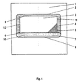
- Fig. 1 shows the top view of an embodiment of a sunroof according to the invention.
- the sunroof opening is located in the inner roof with the front edges 9, the rear edge 10, the left edge 11 and the right edge 12.
- the rear edge 8 of the sunroof cutout can also be seen in the outer roof panel 1 and between the outer Roof plate 1 and inner roof 4, retracted sliding covers 7.
- the structure described so far corresponds to a conventional sunroof with essentially rectangular opening sunroof.
- the resulting one clear sunroof opening 3 is without the modification 5 to vome and to the sides like the sunroof opening in the inner roof 4 from the edges 9, 11 and 12 limited.
- To the rear is the resulting clear sunroof opening 3 depending on the current position of the sliding cover 7 either limited by the front edge 6, if this is in the direction of travel before edge 10 shown here in dashed lines or otherwise if the Edge 10 is located in the direction of travel in front of the edge 6 of the sliding cover 7, from the Edge 10 and thus corresponds to the sunroof opening in the inner roof 4.
- the sunroof 7 is movably attached and can be used to completely close the Roof to be moved forward.
- the opening length of the resulting clear sunroof opening 3, i.e. the distance between the edge 9 and the Edge 6 of the sliding cover 7 or edge 10 is critical of the buzzer.
- the in Fig. 1st illustrated exemplary embodiment of the invention Cover 5 is wholly or partly at the level of the sliding cover 7 in such a way that a partial covering of the substantially rectangular resulting sliding roof opening 3 takes place in the rear corner area.
- the comparison is always in the left half of the roof in the direction of travel modified section of a sunroof shown.
- the modification of the rear outer corner areas can be both one-sided and both-sided be made.
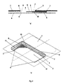
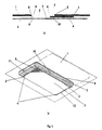
- FIG. 2 shows a flat embodiment of the invention, in which the Modification of the geometry of the corners of the resulting clear sunroof opening 3 by means of the cover 5 completely at the level of the sliding cover 7 is made.
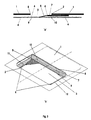
- FIG 3 shows another advantageous embodiment, in which the modification of the corner geometry of the resulting clearances Sunroof opening 3 by means of the cover 5 to the rear at the level of Sliding cover 7 is made, but towards the front up to the height of the inner roof 4 extends down.
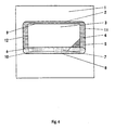
- FIG. 4 is another embodiment of the Device outlined according to the invention.
- the top view corresponds to FIG. 4 perspective and from the designations Fig. 1.
- the invention Cover 5 with which the modification of the corner geometry of the resulting clear sunroof opening 3 is reached, at the level of Inner roof 4 arranged.
- the shown advantageous embodiment of the Cover according to the invention is partially behind the edge of the sliding cover 6 and is therefore partly covered by sliding cover 7. This is in 5 'a' and Fig. 5 'b' particularly clearly visible.
- the flat embodiment the modification 5 is located clearly below the sliding cover 7 at the level of the inner roof 4 and covers part of the rear corners of the resulting clear sunroof opening 3.
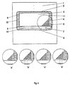
- FIG. 6 'a' shows an exemplary embodiment which is at the level of the sliding cover 7 is flush with the front edge 6 of the same.
- the cover 5 is in the Projection onto the inner roof 4 at its edge 11 and can, but need not necessary to be tightly connected to the two edges 6 and / or 11.
- the cover 5 is in the Projection onto the inner roof 4 on the edge 11, in the rear area it points however, a horizontal distance from the front edge 6 of the sliding cover 7.
- the embodiment in FIG. 6 'c' sits flush with the front edge 6 of the sliding cover 7, but does not lie in the projection onto the inner roof 4 directly at its edge 11, while the advantageous one shown in FIG. 6 'd' Embodiment bears neither on the edge 6 nor on the edge 11.
- the Cover according to the invention can in addition to the positions shown in FIGS. 1 to 5 for example between the sliding cover 7 and inner roof 4 or can also be arranged above the sliding cover 7.
- the modification can. inclined downwards, similarly to FIG. 3, but also inclined upwards.
- the inclination and position of the modification should be chosen so that the projection in the level parallel to the roof panel 1 or to the sliding cover 7 is sufficient large blocking area in the area of the rear corners of the resulting clear sunroof opening 3 results.
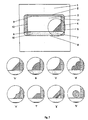
- the cover according to the invention for modifying the corner geometry in the rear area of the essentially rectangular or trapezoidal resulting clear sliding roof opening 3 of a conventional sliding roof, basically all geometric basic shapes are possible in the plane parallel to the roof panel. These are, for example, triangle, rectangle, trapezoid or rounded shapes, such as circles or convex or concave arches, as well as section combinations of segments of these shapes. Some examples of such geometric shapes can be seen in the top view according to FIG. 7.
- the cover 5 according to the invention is positioned flush with the sliding cover 7 with the same and in the projection onto the inner roof 4 against its right edge 11.
- Fig. 7 'a' shows a triangular basic shape of the cover 5 according to the invention. In Fig.
- FIG. 7 'b' this triangular basic shape was combined with a convex arc segment.
- Fig. 7 'c' shows a combination of the triangular basic shape with a concave arc segment.
- Such a combination with sectionally convex arc segments is shown in FIG. 7 'd', in FIG. 7 'e' the triangular basic shape is combined with concave elements.
- 7 'f' and 7 'g' show two examples of trapezoidal corner modifications, while in Fig. 7 'h' a circular surface covers part of the rear corner of the resulting clear sunroof opening 3.
- Cover in the top view of the sunroof are also Bulges, protuberances or other deviations from the flat two-dimensional Geometry possible.
- Fig. 8 'a' and Fig. 8 'b' are two exemplary 'three-dimensional' embodiments outlined at the level of the sliding cover 7. Both embodiments show a triangular basic shape in the plan view of the sunroof. In Fig. 8 'a' this basic shape is arched upwards, while Fig. 8 'b' is arched behind has below. Common to all embodiments is the property that the resulting clear sunroof opening 3 in the area of the rear corners is covered sufficiently strongly.
- the to modify the corners or for a corresponding shaping too Materials used are to be designed so that the flow in the rear outer corner area of the resulting clear sunroof opening 3 can be disturbed sufficiently strongly. This can be done with rigid flow-impermeable materials, such as sheet steel, wood, plastic, as well with elastic wholly or partially flow-impermeable materials, such as Cloth, foil or similar, which in the rear outer corner area of the resulting clear sunroof opening 3 with a corresponding device is spanned.
- FIG. 9a for the technical implementation on a conventional, essentially rectangular sunroof is the invention Cover 5 stowed in a recess 14 in the sliding cover 7.
- the illustrated Cover 5 has a triangular, flat basic shape and is on Height of the sliding cover 7.
- the triangle 5 is at a corner over a Pivotal point 13 connected to the front edge of the sliding cover 6.
- the Sliding cover 7 is constructed like a sandwich, so that the flat triangle 5 around the pivot point 13 can be screwed into the lid, as in Fig. 9a outlined.
- the cover 5 according to the invention formed as a flat triangle, in a recess 15 in the outer edge of the Sunroof cutout, between inner roof 4 and outer roof panel 1, for example at the level of the sliding cover 7, stowed.
- the Cover according to the invention when retracting the sliding cover 7 from boom-critical opening length of the resulting clear sunroof opening 3 from the outside in the area of the rear corners of the resulting clear sliding roof opening 3 pushed in.
- an advantageous embodiment of the invention is used to reduce the buzzing on the Mercedes-Benz S202 (station wagon of the C-Class), which buzzes considerably in the basic configuration (without wind deflector) when the sunroof is fully open.
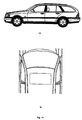
- a side view in FIG. 10 'a' The direction of travel is in the direction of the left edge of the image.
- 10 'b' shows a section of the vehicle in a top view from above. The direction of travel is oriented towards the top of the picture.
- the sunroof is located symmetrically to the direction of travel in the middle of the roof panel just behind the windshield.
- FIG. 11 is a top view of the sunroof of the S202 at complete retracted sliding cover with a particularly effective embodiment shown the cover of the invention.
- the direction of travel is in the direction of the upper edge of the picture.
- the resulting light Sliding roof opening is changed in such a way that two from one rigid material, such as wood or sheet metal consisting of flat triangular boards the rear corners at the level of the sliding cover, flush with the same and the Be installed on the inside roof.
- the two right-angled isosceles triangular boards, as can be seen in Fig. 11, have a leg length of 200 mm and a thickness of 5 mm.
- the cutout in the roof panel is Mercedes-Benz S202 as shown in Fig. 11 440 mm x 860 mm.
- the boards because of the easier fastening options with the edge of the inner roof from the sliding cover attached a few degrees to the bottom.
- the flush used here Connection of the boards with the edge of the inner roof and the Sliding lid is made with aluminum tape (Scotch Pressure Sensitive Tape).
- the Booming of the S202 can be reduced so much that it subjectively no longer perceptible. This is measured in the wind tunnel The determined situation is subjective through first driving tests with the Vehicle type S202 (C-Class station wagon) has been confirmed.
Landscapes
- Engineering & Computer Science (AREA)
- Mechanical Engineering (AREA)
- Body Structure For Vehicles (AREA)
- Vehicle Interior And Exterior Ornaments, Soundproofing, And Insulation (AREA)
Description
- Durch eine Weiterentwicklung von Schiebedächer mit im wesentlichen rechteckiger, aber auch trapezförmiger resultierender Schiebedachöffnung, beispielsweise durch das Vorsehen von Klapp-, Schiebe-, Drehoder Spannmechanismen zum Ausfahren oder Spannen unterschiedlicher Ausführungsformen der erfindungsgemäßen Abdeckung bei wummerkritischen Öffnungslängen der resultierenden lichten Schiebedachöffnung oder durch eine entsprechende Nachrüstung vorhandener Schiebedächer mit im wesentlichen rechteckiger oder trapezförmiger resultierender lichter Schiebedachöffnung.
- Neu zu entwickelnde Schiebedächer können alternativ eine resultierende lichte Schiebedachöffnung erhalten, welche ausgehend von einer im wesentlichen rechteckigen resultierenden lichten Schiebedachöffnung eine den o.g. Eckenabdeckung entsprechende Form erhält.
- Auch eine Kombination aus teilweise Formänderung einer ursprünglich im wesentlichen rechteckigen resultierenden lichten Schiebedachöffnung und teilweise zufügbarer Abdeckung ist denkbar.
- Fig. 1
- eine Draufsicht auf ein erfindungsgemäßes Schiebedach;
- Fig. 2
- eine Querschnittszeichnung (oben) und eine Schrägansicht (unten) eines erfindungsgemäßen Schiebedachs;
- Fig. 3
- eine Querschnittszeichnung (oben) und eine Schrägansicht (unten) eines erfindungsgemäßen Schiebedachs;
- Fig. 4
- eine Draufsicht auf ein erfindungsgemäßes Schiebedach;
- Fig. 5
- eine Querschnittszeichnung (oben) und eine Schrägansicht (unten) eines erfindungsgemäßen Schiebedachs;
- Fig. 6
- eine Draufsicht auf ein erfindungsgemäßes Schiebedach, sowie mehrere beispielhafte Varianten zur Anbringung der Abdeckung in der horizontalen Ebene des Schiebedeckels;
- Fig. 7
- eine Draufsicht auf ein erfindungsgemäßes Schiebedach, sowie mehrere beispielhafte geometrische Varianten für die Abdeckung;
- Fig. 8 'a' und Fig. 8 'b'
- zwei dreidimensionale Schrägansichten auf erfindungsgemäße Schiebedächer;
- Fig. 9 'a' und Fig. 9 'b'
- zwei Draufsichten auf erfindungsgemäße Schiebedächer mit unterschiedlichen Mechanismen zur Zuschaltung der Abdeckung;
- Fig. 10
- Skizzen eines Mercedes-Benz Serienfahrzeuges S202 (C-Klasse-Kombi) in Seitenansicht und Draufsicht;
- Fig. 11
- eine Technische Skizze in Draufsicht auf das erfindungsgemäße Schiebedach an Bord eines Mercedes-Benz S202 (C-Klasse-Kombi).
Fig. 7 'a' zeigt eine dreieckige Grundform der erfindungsgemäßen Abdeckung 5. In Fig. 7 'b' wurde diese dreieckige Grundform mit einem konvexen Bogensegment kombiniert. Fig. 7 'c' zeigt eine Kombination der dreieckigen Grundform mit einem konkaven Bogensegment. In Fig. 7 'd' ist eine solche Kombination mit abschnittsweise konvexen Bogensegmenten abgebildet, in Fig. 7 'e' ist die dreieckige Grundform mit konkaven Elementen kombiniert. Die Fig. 7 'f' und und 7 'g' zeigen zwei Beispiele trapezförmiger Eckenmodifikationen, während in Fig. 7 'h' eine kreisförmige Fläche einen Teil der hinteren Ecke der resultierenden lichten Schiebedachöffnung 3 verdeckt.
Um eine bessere Vorstellung von der Position der erfindungsgemäßen Vorrichtung am Fahrzeug zu bekommen, ist dieses in Fig. 10 'a' als Seitenansicht dargestellt. Die Fahrtrichtung befindet sich in Richtung des linken Bildrandes. Fig. 10 'b' zeigt einen Ausschnitt des Fahrzeuges in Draufsicht von oben. Die Fahrtrichtung ist hier in Richtung des oberen Bildrandes orientiert. Das Schiebedach befindet sich, wie aus Fig. 10 'b' ersichtlich zur Fahrtrichtung symmetrisch in der Mitte des Dachbleches kurz hinter der Windschutzscheibe.
- 1
- äußeres Dachblech des Fahrzeuges
- 2
- Vorderkante des Schiebedachausschnittes
- 3
- resultierende lichte Schiebedachöffnung
- 4
- Innendach
- 5
- erfindungsgemäße Abdeckung
- 6
- Vorderkante des Schiebedeckels 7
- 7
- Schiebedeckel
- 8
- Hinterkante des Schiebedachausschnittes
- 9
- Vordere Kante der Schiebedachöffnung im Innendach 4
- 10
- Hintere Kante der Schiebedachöffnung im Innendach 4
- 11
- Rechte Kante der Schiebedachöffnung im Innendach 4
- 12
- Linke Kante der Schiebedachöffnung im Innendach 4
- 13
- Drehpunkt
- 14
- Aussparung im Schiebedeckel 7
- 15
- Aussparung im Rand des Schiebedachausschnittes
Claims (13)
- Schiebedach für Kraftfahrzeuge mit reduziertem Schiebedachwummern, umfassend eine Schiebedachöffnung sowie einen beweglichen Schiebedeckel (7) zur Abdeckung der Schiebedachöffnung, wobei abhängig von der aktuellen Stellung des Schiebedeckels (7) eine resultierende lichte Schiebedachöffnung (3) gebildet ist, gekennzeichnet durch eine Modifikation der Geometrie von Schiebedächern mit im wesentlichen rechteckiger oder trapezförmiger resultierender lichter Schiebedachöffnung durch teilweise oder vollständige Abdeckung (5) von mindestens einem der in Fahrtrichtung gesehen hinteren Eckbereiche der resultierenden lichten Schiebedachöffnung (3).
- Schiebedach nach Anspruch 1, dadurch gekennzeichnet, daß die Abdeckung (5) mittels eines oder mehrerer separater, zuschaltbarer Elemente realisiert ist.
- Schiebedach nach Anspruch 1 oder 2, dadurch gekennzeichnet, daß die Abdeckung (5) mittels entsprechender Formgebung der Schiebedachbauelemente realisiert ist.
- Schiebedach nach einem der vorangehenden Ansprüche, dadurch gekennzeichnet, daß die Abdeckung (5) eine geometrische Grundform, wie Dreieck, Rechteck, Trapez oder eine abgerundete Form, wie Kreis oder konvexe oder konkave Bögen, oder abschnittsweise eine Kombination aus einzelnen Segmenten dieser Formen aufweist.
- Schiebedach nach einem der vorangehenden Ansprüche, dadurch gekennzeichnet, daß die Abdeckung (5) eine in sich ebene Geometrie aufweist.
- Schiebedach nach einem der vorangehenden Ansprüche, dadurch gekennzeichnet, daß die Abdeckung (5) und der in Fahrtrichtung gesehen vordere Bereich des Schiebedeckels (7) sich teilweise übertappen.
- Schiebedach nach einem der vorangehenden Ansprüche, dadurch gekennzeichnet, daß die Abdeckung (5) Wölbungen, Ausstülpungen oder sonstige Abweichungen von der ebenen Geometrie aufweist.
- Schiebedach nach einem der vorangehenden Ansprüche, dadurch gekennzeichnet, daß die Abdeckung (5) auf Höhe des Schiebedeckels (7), des Innendaches (4) oder beliebigen vertikalen Positionen dazwischen angeordnet ist.
- Schiebedach nach einem der vorangehenden Ansprüche, dadurch gekennzeichnet, daß die Abdeckung (5) bündig mit dem in Fahrtrichtung gesehen hinteren Rand der resultierenden lichten Schiebedachöffnung (3) angeordnet ist.
- Schiebedach nach einem der vorangehenden Ansprüche, dadurch gekennzeichnet, daß die Abdeckung (5) in der Projektion auf die resultierende lichte Schiebedachöffnung (3) an deren in Fahrtrichtung gesehen hinterem Rand anliegt.
- Schiebedach nach einem der vorangehenden Ansprüche, dadurch gekennzeichnet, daß die Abdeckung (5) bündig mit dem seitlichen Rand (11,12) der resultierenden lichten Schiebedachöffnung (3) angeordnet ist.
- Schiebedach nach einem der vorangehenden Ansprüche, dadurch gekennzeichnet, daß die Abdeckung (5) in der Projektion auf die resultierende lichte Schiebedachöffnung (3) an deren seitlichem Rand (11,12) anliegt.
- Schiebedach nach einem der vorangehenden Ansprüche, dadurch gekennzeichnet, daß die Abdeckung (5) aus einem starren, strömungsundurchlässigen Material, wie Stahlblech, Holz, Kunststoff, Sicherheitsglas, o.ä. oder elastischen ganz oder teilweise strömungsundurchlässigen Materialien, wie Tuch, Folie o.ä., besteht.
Applications Claiming Priority (3)
| Application Number | Priority Date | Filing Date | Title |
|---|---|---|---|
| DE19706673 | 1997-02-20 | ||
| DE19706673A DE19706673C2 (de) | 1997-02-20 | 1997-02-20 | Schiebedach für Kraftfahrzeuge mit einer Vorrichtung zur Reduzierung der bei einer bestimmten Öffnungsweite des Schiebedeckels und einer bestimmten Fahrzeuggeschwindigkeit auftretenden Wummergeräusche |
| PCT/EP1998/000935 WO1998036926A1 (de) | 1997-02-20 | 1998-02-19 | Schiebedach für kraftfahrzeuge mit reduziertem schiebedachwummern |
Publications (2)
| Publication Number | Publication Date |
|---|---|
| EP0961704A1 EP0961704A1 (de) | 1999-12-08 |
| EP0961704B1 true EP0961704B1 (de) | 2002-05-02 |
Family
ID=7820905
Family Applications (1)
| Application Number | Title | Priority Date | Filing Date |
|---|---|---|---|
| EP98912329A Expired - Lifetime EP0961704B1 (de) | 1997-02-20 | 1998-02-19 | Schiebedach für kraftfahrzeuge mit reduziertem schiebedachwummern |
Country Status (6)
| Country | Link |
|---|---|
| US (1) | US6244654B1 (de) |
| EP (1) | EP0961704B1 (de) |
| JP (1) | JP2000509677A (de) |
| DE (2) | DE19706673C2 (de) |
| ES (1) | ES2175693T3 (de) |
| WO (1) | WO1998036926A1 (de) |
Families Citing this family (4)
| Publication number | Priority date | Publication date | Assignee | Title |
|---|---|---|---|---|
| DE19937459B4 (de) * | 1999-08-07 | 2008-10-16 | Volkswagen Ag | Verfahren und Vorrichtung zur automatischen Veränderung einer Öffnung in der Außenhaut einer Fahrzeugkabine |
| FR2820689B1 (fr) | 2001-02-12 | 2003-12-12 | Renault | Systeme de reduction du battement de toit ouvrant dans un vehicule automobile |
| US20040109025A1 (en) * | 2002-08-28 | 2004-06-10 | Jean-Marie Hullot | Computer program comprising a plurality of calendars |
| DE102010050424A1 (de) * | 2010-11-04 | 2011-06-30 | Daimler AG, 70327 | Schiebe- und/oder Hebedach für einen Kraftwagen |
Family Cites Families (9)
| Publication number | Priority date | Publication date | Assignee | Title |
|---|---|---|---|---|
| US2094932A (en) * | 1935-08-20 | 1937-10-05 | Swan Eric Hargreaves | Means for screening roof ventilation apertures in motor cars |
| FR1277910A (fr) * | 1961-01-25 | 1961-12-01 | Déflecteur transparent parasolaire susceptible d'occuper plusieurs positions à l'intérieur d'un véhicule | |
| JPS60110007U (ja) * | 1983-12-28 | 1985-07-26 | ダイキヨ−・ベバスト株式会社 | 乗物の屋根窓における換気装置 |
| JPS60169322A (ja) * | 1984-02-14 | 1985-09-02 | Nissan Motor Co Ltd | 車両用摺動式屋根のデイフレクタ取付構造 |
| DE3441776A1 (de) * | 1984-11-15 | 1986-05-22 | Adam Opel AG, 6090 Rüsselsheim | Verfahren zum anbringen einer dichtung an der aussenkante eines bauteils sowie bauteil mit einer solchen dichtung |
| JPH02193715A (ja) * | 1989-01-20 | 1990-07-31 | Fuji Heavy Ind Ltd | 自動車用サンルーフ構造 |
| DE9007234U1 (de) * | 1990-06-29 | 1990-09-06 | HS Technik und Design Technische Entwicklungen GmbH, 8000 München | Windabweiser |
| DE4126568A1 (de) * | 1991-08-10 | 1993-02-11 | Audi Ag | Windabweiser an einem schiebedach eines kraftfahrzeuges |
| DE4402314C2 (de) * | 1994-01-27 | 1996-04-04 | Daimler Benz Ag | Netz zur Abdeckung von Schiebedachöffnungen |
-
1997
- 1997-02-20 DE DE19706673A patent/DE19706673C2/de not_active Expired - Fee Related
-
1998
- 1998-02-19 WO PCT/EP1998/000935 patent/WO1998036926A1/de not_active Ceased
- 1998-02-19 ES ES98912329T patent/ES2175693T3/es not_active Expired - Lifetime
- 1998-02-19 EP EP98912329A patent/EP0961704B1/de not_active Expired - Lifetime
- 1998-02-19 DE DE59803978T patent/DE59803978D1/de not_active Expired - Fee Related
- 1998-02-19 US US09/367,719 patent/US6244654B1/en not_active Expired - Fee Related
- 1998-02-19 JP JP10536247A patent/JP2000509677A/ja active Pending
Also Published As
| Publication number | Publication date |
|---|---|
| WO1998036926A1 (de) | 1998-08-27 |
| JP2000509677A (ja) | 2000-08-02 |
| US6244654B1 (en) | 2001-06-12 |
| DE19706673C2 (de) | 1999-08-05 |
| DE59803978D1 (de) | 2002-06-06 |
| DE19706673A1 (de) | 1998-09-24 |
| ES2175693T3 (es) | 2002-11-16 |
| EP0961704A1 (de) | 1999-12-08 |
Similar Documents
| Publication | Publication Date | Title |
|---|---|---|
| DE19958748B4 (de) | Vorrichtung zur Beeinflussung der Luftströmung | |
| EP0374421B1 (de) | Windabweiser für Schiebedächer, herausnehmbare Dachabschnitte oder dergleichen von Kraftfahrzeugen | |
| DE3308065C2 (de) | ||
| DE4033027A1 (de) | Vorrichtung zur geraeusch- und schwingungsminderung an tangential ueberstroemten oeffnungen von kraftfahrzeugen, insbesondere an schiebedachoeffnungen | |
| DE60131478T3 (de) | Konstruktion eines öffnungsfähigen Fahrzeugdaches | |
| EP3250405B1 (de) | Windleiteinrichtung für einen offenen personenkraftwagen | |
| DE69104028T2 (de) | Lastsicherungsvorrichtung. | |
| DE19706673C2 (de) | Schiebedach für Kraftfahrzeuge mit einer Vorrichtung zur Reduzierung der bei einer bestimmten Öffnungsweite des Schiebedeckels und einer bestimmten Fahrzeuggeschwindigkeit auftretenden Wummergeräusche | |
| DE102018113773A1 (de) | Fahrzeug-Kofferraumdeckelspoiler mit aerodynamisch geformten Flügelabschnitten | |
| EP1981727A1 (de) | Windabweiser im kraftfahrzeugbereich | |
| WO2001008912A1 (de) | Luftausströmer mit lamellen | |
| DE102018129562A1 (de) | Luftausströmer für ein fahrzeug sowie belüftungssystem mit einem solchen luftausströmer | |
| DE3213820A1 (de) | Spoilerhaube fuer lkw-fahrerhausdaecher | |
| DE102018213770A1 (de) | Heckseitige Luftleitvorrichtung für ein Fahrzeug | |
| EP3456591A1 (de) | Bauteilsystem zur fixierung eines verkleidungsteils und kraftfahrzeug | |
| DE4142265C1 (en) | Car sun roof with rigid lid(s) - has roof railing with side screens along its length in section protruding beyond roof skin in sun roof open position | |
| DE3930054C2 (de) | ||
| DE4335103C1 (de) | Windschutz für Fahrzeuge, insbesondere an einem Cabriolet, Roadster oder dergleichen | |
| DE4026650C2 (de) | ||
| EP0747250B1 (de) | Dynamische Windabweiseranordnung | |
| DE102004027087A1 (de) | Vorrichtung zur Geräusch- und Schwingungsminderung | |
| DE102018211970B4 (de) | Kraftfahrzeug mit einer verschließbaren Dachöffnung | |
| EP1674312B1 (de) | Seitenfensterrollo für Kraftfahrzeuge | |
| DE4418913A1 (de) | Windabweisvorrichtung für Fahrzeuge, vorzugsweise Kraftfahrzeuge | |
| DE3223750A1 (de) | Ausstell-schiebedach fuer kraftfahrzeuge |
Legal Events
| Date | Code | Title | Description |
|---|---|---|---|
| PUAI | Public reference made under article 153(3) epc to a published international application that has entered the european phase |
Free format text: ORIGINAL CODE: 0009012 |
|
| 17P | Request for examination filed |
Effective date: 19990716 |
|
| AK | Designated contracting states |
Kind code of ref document: A1 Designated state(s): DE ES FR GB IT |
|
| 17Q | First examination report despatched |
Effective date: 20001227 |
|
| GRAG | Despatch of communication of intention to grant |
Free format text: ORIGINAL CODE: EPIDOS AGRA |
|
| GRAG | Despatch of communication of intention to grant |
Free format text: ORIGINAL CODE: EPIDOS AGRA |
|
| GRAH | Despatch of communication of intention to grant a patent |
Free format text: ORIGINAL CODE: EPIDOS IGRA |
|
| GRAH | Despatch of communication of intention to grant a patent |
Free format text: ORIGINAL CODE: EPIDOS IGRA |
|
| REG | Reference to a national code |
Ref country code: GB Ref legal event code: IF02 |
|
| GRAA | (expected) grant |
Free format text: ORIGINAL CODE: 0009210 |
|
| AK | Designated contracting states |
Kind code of ref document: B1 Designated state(s): DE ES FR GB IT |
|
| REG | Reference to a national code |
Ref country code: GB Ref legal event code: FG4D Free format text: NOT ENGLISH |
|
| REF | Corresponds to: |
Ref document number: 59803978 Country of ref document: DE Date of ref document: 20020606 |
|
| GBT | Gb: translation of ep patent filed (gb section 77(6)(a)/1977) |
Effective date: 20020802 |
|
| ET | Fr: translation filed | ||
| ET | Fr: translation filed | ||
| REG | Reference to a national code |
Ref country code: ES Ref legal event code: FG2A Ref document number: 2175693 Country of ref document: ES Kind code of ref document: T3 |
|
| PGFP | Annual fee paid to national office [announced via postgrant information from national office to epo] |
Ref country code: GB Payment date: 20030130 Year of fee payment: 6 |
|
| PGFP | Annual fee paid to national office [announced via postgrant information from national office to epo] |
Ref country code: ES Payment date: 20030218 Year of fee payment: 6 |
|
| PLBE | No opposition filed within time limit |
Free format text: ORIGINAL CODE: 0009261 |
|
| STAA | Information on the status of an ep patent application or granted ep patent |
Free format text: STATUS: NO OPPOSITION FILED WITHIN TIME LIMIT |
|
| 26N | No opposition filed |
Effective date: 20030204 |
|
| PG25 | Lapsed in a contracting state [announced via postgrant information from national office to epo] |
Ref country code: GB Free format text: LAPSE BECAUSE OF NON-PAYMENT OF DUE FEES Effective date: 20040219 |
|
| PG25 | Lapsed in a contracting state [announced via postgrant information from national office to epo] |
Ref country code: ES Free format text: LAPSE BECAUSE OF NON-PAYMENT OF DUE FEES Effective date: 20040220 |
|
| GBPC | Gb: european patent ceased through non-payment of renewal fee |
Effective date: 20040219 |
|
| PGFP | Annual fee paid to national office [announced via postgrant information from national office to epo] |
Ref country code: DE Payment date: 20050208 Year of fee payment: 8 |
|
| PGFP | Annual fee paid to national office [announced via postgrant information from national office to epo] |
Ref country code: FR Payment date: 20050210 Year of fee payment: 8 |
|
| PG25 | Lapsed in a contracting state [announced via postgrant information from national office to epo] |
Ref country code: IT Free format text: LAPSE BECAUSE OF NON-PAYMENT OF DUE FEES;WARNING: LAPSES OF ITALIAN PATENTS WITH EFFECTIVE DATE BEFORE 2007 MAY HAVE OCCURRED AT ANY TIME BEFORE 2007. THE CORRECT EFFECTIVE DATE MAY BE DIFFERENT FROM THE ONE RECORDED. Effective date: 20050219 |
|
| REG | Reference to a national code |
Ref country code: ES Ref legal event code: FD2A Effective date: 20040220 |
|
| PG25 | Lapsed in a contracting state [announced via postgrant information from national office to epo] |
Ref country code: DE Free format text: LAPSE BECAUSE OF NON-PAYMENT OF DUE FEES Effective date: 20060901 |
|
| REG | Reference to a national code |
Ref country code: FR Ref legal event code: ST Effective date: 20061031 |
|
| PG25 | Lapsed in a contracting state [announced via postgrant information from national office to epo] |
Ref country code: FR Free format text: LAPSE BECAUSE OF NON-PAYMENT OF DUE FEES Effective date: 20060228 |