EP0961668B1 - VERFAHREN ZUM VERMEIDEN ODER REDUZIEREN DER FORMUNG VON MAGNETISMUS ZWISCHEN ZWEI BENACHBARTEN GEGENSINNIG DREHENDEN KREISSäGEBLäTTER UND VORRICHTUNG ZUR DURCHFüHRUNG DES VERFAHRENS - Google Patents
VERFAHREN ZUM VERMEIDEN ODER REDUZIEREN DER FORMUNG VON MAGNETISMUS ZWISCHEN ZWEI BENACHBARTEN GEGENSINNIG DREHENDEN KREISSäGEBLäTTER UND VORRICHTUNG ZUR DURCHFüHRUNG DES VERFAHRENS Download PDFInfo
- Publication number
- EP0961668B1 EP0961668B1 EP96935671A EP96935671A EP0961668B1 EP 0961668 B1 EP0961668 B1 EP 0961668B1 EP 96935671 A EP96935671 A EP 96935671A EP 96935671 A EP96935671 A EP 96935671A EP 0961668 B1 EP0961668 B1 EP 0961668B1
- Authority
- EP
- European Patent Office
- Prior art keywords
- grooves
- saw
- saw blades
- saw blade
- extension
- Prior art date
- Legal status (The legal status is an assumption and is not a legal conclusion. Google has not performed a legal analysis and makes no representation as to the accuracy of the status listed.)
- Expired - Lifetime
Links
Images


Classifications
-
- B—PERFORMING OPERATIONS; TRANSPORTING
- B23—MACHINE TOOLS; METAL-WORKING NOT OTHERWISE PROVIDED FOR
- B23D—PLANING; SLOTTING; SHEARING; BROACHING; SAWING; FILING; SCRAPING; LIKE OPERATIONS FOR WORKING METAL BY REMOVING MATERIAL, NOT OTHERWISE PROVIDED FOR
- B23D61/00—Tools for sawing machines or sawing devices; Clamping devices for these tools
- B23D61/02—Circular saw blades
- B23D61/025—Details of saw blade body
- B23D61/0275—Slots in the saw blade body for reducing tension or vibration
-
- B—PERFORMING OPERATIONS; TRANSPORTING
- B23—MACHINE TOOLS; METAL-WORKING NOT OTHERWISE PROVIDED FOR
- B23D—PLANING; SLOTTING; SHEARING; BROACHING; SAWING; FILING; SCRAPING; LIKE OPERATIONS FOR WORKING METAL BY REMOVING MATERIAL, NOT OTHERWISE PROVIDED FOR
- B23D61/00—Tools for sawing machines or sawing devices; Clamping devices for these tools
- B23D61/02—Circular saw blades
- B23D61/025—Details of saw blade body
-
- B—PERFORMING OPERATIONS; TRANSPORTING
- B27—WORKING OR PRESERVING WOOD OR SIMILAR MATERIAL; NAILING OR STAPLING MACHINES IN GENERAL
- B27B—SAWS FOR WOOD OR SIMILAR MATERIAL; COMPONENTS OR ACCESSORIES THEREFOR
- B27B5/00—Sawing machines working with circular or cylindrical saw blades; Components or equipment therefor
- B27B5/29—Details; Component parts; Accessories
- B27B5/30—Details; Component parts; Accessories for mounting or securing saw blades or saw spindles
- B27B5/34—Devices for securing a plurality of circular saw blades on a single saw spindle; Equipment for adjusting the mutual distance
-
- Y—GENERAL TAGGING OF NEW TECHNOLOGICAL DEVELOPMENTS; GENERAL TAGGING OF CROSS-SECTIONAL TECHNOLOGIES SPANNING OVER SEVERAL SECTIONS OF THE IPC; TECHNICAL SUBJECTS COVERED BY FORMER USPC CROSS-REFERENCE ART COLLECTIONS [XRACs] AND DIGESTS
- Y10—TECHNICAL SUBJECTS COVERED BY FORMER USPC
- Y10T—TECHNICAL SUBJECTS COVERED BY FORMER US CLASSIFICATION
- Y10T83/00—Cutting
- Y10T83/04—Processes
-
- Y—GENERAL TAGGING OF NEW TECHNOLOGICAL DEVELOPMENTS; GENERAL TAGGING OF CROSS-SECTIONAL TECHNOLOGIES SPANNING OVER SEVERAL SECTIONS OF THE IPC; TECHNICAL SUBJECTS COVERED BY FORMER USPC CROSS-REFERENCE ART COLLECTIONS [XRACs] AND DIGESTS
- Y10—TECHNICAL SUBJECTS COVERED BY FORMER USPC
- Y10T—TECHNICAL SUBJECTS COVERED BY FORMER US CLASSIFICATION
- Y10T83/00—Cutting
- Y10T83/283—With means to control or modify temperature of apparatus or work
- Y10T83/293—Of tool
-
- Y—GENERAL TAGGING OF NEW TECHNOLOGICAL DEVELOPMENTS; GENERAL TAGGING OF CROSS-SECTIONAL TECHNOLOGIES SPANNING OVER SEVERAL SECTIONS OF THE IPC; TECHNICAL SUBJECTS COVERED BY FORMER USPC CROSS-REFERENCE ART COLLECTIONS [XRACs] AND DIGESTS
- Y10—TECHNICAL SUBJECTS COVERED BY FORMER USPC
- Y10T—TECHNICAL SUBJECTS COVERED BY FORMER US CLASSIFICATION
- Y10T83/00—Cutting
- Y10T83/929—Tool or tool with support
- Y10T83/9372—Rotatable type
- Y10T83/9403—Disc type
Definitions
- the present invention relates to a method for preventing or reducing formation of magnetism in two adjacently located saw blades rotating in opposed rotary directions in relation to each other, and a device for utilization of the method SE, B, 458 096, according to the preamble of claim 2, discloses a pair of saw blades, comprising two in relation to each other adjacently located saw blades, arranged while rotating in relation to each other opposed rotary directions to take up a saw cut in a workpiece in a common and interacting operation. According to this prior patent publication internal contact between the saw blades is prevented by application of a pneumatic or hydraulic pressure between the saw blades.
- each saw blade is arranged with embossed portions from an outer side plane, arranged to form channels open against the rotary direction. Further improvements of such an interacting pair of saw blades are proposed in SE Patent Appln. No. 9403767-8, primarily intended to improve the cut surface of a workpiece and to reduce burr formation, but also this embodiment is based on that the pair of interacting saw blades are maintained separated by application of a pneumatic or hydraulic pressure.
- the object of the present invention is to disclose a method for reducing formation of magnetism in a pair of saw blades of the above mentioned type, which during a starting phase also results in that the adjacently located saw blades move in a parallel relationship, without the above mentioned oscillating movements in relation to each other.
- the invention also relates to a device for utilization of the method.
- each saw blade is arranged having a number of substantially radially extending through grooves having an extension within the area of the rotary centre for each saw blade and the surrounding saw teeth area, arranged when rotating to remove air existing between adjacent planes of the saw blades, and thereby prevent or reduce magnetization of the saw blades.
- each saw blade is arranged having a number of substantially radially extending through grooves having an extension within the area of the rotary centre for each saw blade and the surrounding saw teeth area, arranged when rotating to remove air existing between adjacent planes of the saw blades.
- the problem with strong magnetization of two adjacently located saw blades rotating in opposed directions may be related to ionization of intermediately located air molecules in association with formation of a magnetic/electrical changing field, and this phenomena also influences the saw blades during an initial start phase, and as a result, the saw blades do not move in a parallel relationship to each other.
- the saw blades have been regarded as stable in relation to each other, e.g. by arranging air channels in the saw blades, which when rotated supply air to the space between the saw blades, and thus stabilize same during a sawing operation by means of a pneumatic force.
- the method according to the present invention is based on an important and in this connection surprising change of previously accepted technology, namely to remove air existing between the saw blades by means of preferably substantially radially extending through penetrating grooves in the area between the central portion of the saw blades and the saw teeth area.
- the method according to the present invention results in a surprising effect, on one hand is magnetization of the saw blades avoided (substantially totally), on the other hand will the saw blades receive a stable and parallel motion already when commencing rotation in opposed rotary directions. As a further surprising effect, the saw blades will maintain an adjacent, but separated, relationship.
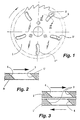
- a saw blade in its entirety denominated 1, is arranged with a number of substantially radially extending through grooves 2, 2', 2", preferably substantially equally angularly separated from each other.
- the grooves 2, 2', 2" have a slightly bent curved extension, with each end portion located as a first portion in the rotary direction of the saw blade 1, and with the central portion as a successively following part.
- This configuration is a preferred configuration, but also opposed extension, or a substantially linear extension, can be used.
- FIG. 2 A groove 2 is shown in cross-section, disclosing that the grooves 2, 2', 2" have a chamfer 3 at the edge portion which is a first edge portion in the rotary direction, and that the grooves 2, 2', 2" have a chamfer 4 in the same direction at the edge portion serving as a final edge portion in the rotary direction.
- the latter chamfer 4 extends from the inner side plane and is inclined towards the outer side plane, whereas the first chamfer 3 is terminated by the edge portion of the grooves 2, 2', 2" which is located by the outer plane of the saw blade 1.
- Fig. 3 shows a portion of two saw blades 1, 1' rotating in an opposed and adjacent relationship.
- Fig. 3 illustrates how the grooves 2, 2', 2" during rotation of the saw blades 1, 1' remove intermediately existing air, an action resulting in that magnetization of the saw blades 1, 1' is avoided, and that the saw blades 1, 1' receive a stable and parallel movement during the initial stage of a sawing operation.
- Previously discussed chamfers 3, 4 result in accomplishment of an increased removal of air, but an acceptable reduction of magnetization of the saw blades 1, 1' is also accomplished without such chamfers.
- Tests have also been made without chamfers 3, 4, and at a number of revolutions of 2.000 rpm disclosed that a groove width of at least 4,8 mm for the grooves 2, 2', 2" was required to prevent magnetization.
- a groove width of at least 6 mm was required to avoid magnetization, i.e. an increased groove width is required for an increased rotary speed.
- the groove width under 3 mm by changing the angle of the chamfers 3, 4.
- the chamfers 3, 4 are given a more pointed angle, reduced approximately 3° for each one millimetre reduction of the groove width, i.e. approximately 42° for a groove width of 2 mm, and approximately 39° for a groove width of 1 mm.
- Chamfers having a more blunt angle than 45° result in a considerably more poor result, and as a result, the width of the grooves 2, 2', 2" can not be reduced as described.
- Also utilized rotary speed has a certain influence on the width of the grooves, particularly when the edge portions of the grooves 2, 2', 2" are not arranged with chamfers, resulting, as previously mentioned, in a need for a larger groove width for an increased rotary speed.
- FIG. 4 and 5 A modified embodiment of a saw blade in relation to Figs. 1 - 3 is shown in Figs. 4 and 5 which in similarity with previously described embodiment includes a number of substantially radially extending through grooves 2, 2', 2", preferably substantially equally angularly spaced from each other.
- the grooves 2, 2', 2" have a slightly bent curved extension, with each end portion located as an initial first portion in the rotary direction of the saw blade 1, and with the central portion as a successively following part.
- This configuration constitutes a preferred configuration, but also reversed extension, or a substantially linear extension, can be used.
- non-penetrating grooves or recesses 5, 5', 5" which are arranged by the plane of the saw blade intended to serve as an adjacent surface in relation to an interacting saw blade.
- the non-penetrating grooves 5, 5', 5" extend circular with from each other different radius from the centre of the saw blade 1.
- the non-penetrating grooves 5, 5', 5" have a relatively small depth, e.g. 0.1 mm, but this depth can be varied from a few hundreds of a millimetre to a few tenths of a millimetre, and even deeper grooves 5, 5', 5" may be used for saw blades having very large diameter. As an example, tests have been performed with extremely good result utilizing a saw blade 1 having a diameter of 230 mm and 7 - 9 non-penetrating grooves 5, 5', 5" with a width of 2 mm and a depth of 0.1 mm or less.
- suitable width/depth for the non-penetrating grooves 5, 5', 5", space between the grooves and number of grooves can obviously be varied within broad limits and with regard taken to the diameter of the saw blade, rotary speed and similar factors.
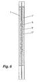
- Fig. 6 is intended to disclose how the grooves 5, 5', 5" can be arranged displaced in relation to each other at two interacting saw blades 1, 1'. Such a relative displacement results in an improved result, but it should be emphasized that the shown degree of displacement can be smaller, and that a fully acceptable result also can be obtained with the grooves 5, 5', 5" located in a substantially opposed relationship.
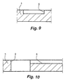
- Figs. 7 and 8 Examples of further modified embodiments are shown in Figs. 7 and 8, intended to increase the effect of previously discussed through grooves 2, 2', 2" by a number of non-penetrating grooves or recesses 5, 5', 5", which are arranged by the plane of the saw blade 1 which is intended to be an adjacent surface in relation to an interacting saw blade.
- the non-penetrating grooves 5, 5', 5" extend curved with a common radius from the centre of the saw blade 1 and having an angular extension which is less than the distance between each other adjacently located through grooves 2, 2', 2".
- Each non-penetrating groove 5, 5', 5" extends from a through groove 2, 2', 2" in the rotary direction of the saw blade 1 (as indicated by an arrow) and is terminated by a closed end portion before the next through groove 2, 2', 2".
- the non-penetrating grooves 5, 5', 5" have a relatively small depth, e.g. 0.1 mm, but this depth can be varied from a few hundreds of a millimetre to a few tenths of a millimetre, and for saw blades having a very large diameter even deeper grooves 5, 5', 5" can be used.
- extremely good results were obtained with a saw blade 1 having a diameter of 230 mm and non-penetrating grooves with a width of 20 mm and a depth of 0.1 mm. Good results were also obtained when the width of the grooves was reduced to 10 mm.
- suitable width/depth of the non-penetrating grooves 5, 5', 5" can obviously be varied within broad limits, related to the diameter of the saw blade 1, rotary speed and similar factors.
- non-penetrating grooves 5, 5', 5" shown in Figs. 7 and 8 may for example be replaced by two or more preferably substantially parallel grooves, i.e. with in relation to each other different radius.
- the groove width for each individual non-penetrating groove 5, 5', 5" can obviously also usually be reduced in relation to embodiments having only one groove 5, 5', 5".
- non-penetrating grooves 5, 5', 5" can also be used in association with through grooves 2, 2', 2" having chamfered side portions, i.e. arranged as disclosed in the embodiment according to Figs. 1 - 3.
- non-penetrating grooves 5, 5', 5" can also be given another length extension than what has been shown and described, e.g. a more straight extension, even though shown curved extension obviously from machining point of view and other aspects is a preferred embodiment.
- the invention is not restricted to the examples relating to groove depth, groove width and number of grooves given earlier, since possibility exists to vary these parameters within a large spectrum.
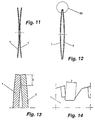
- the saw blade 1 according to the present invention can be further modified in order to secure that the outer portion of same is not deflected away from an adjacent and interacting saw blade 1' during rotation, a situation which is shown exagerrated in Fig. 11.
- the outer peripheral portions of the saw blades 1, 1' are preferably arranged with towards each other facing surfaces initially (prior to a sawing operation) extending in a substantially parallel relationship, as indicated in Fig. 13 as the area "X". This is preferably accomplished by means of a grinding operation, and safeguards that the saw teeth do not intermesh during the rotary movement in opposed directions for the saw blades 1, 1'.
- the angular size which is ground off can be mentioned an angle of 4 - 7 degrees, but the size of the angle is obviously adapted to the bowl shape of the saw blades 1, 1'.
- the above modification can easily be implemented when manufacturing new saw blades 1, 1', as well as for existing saw blades 1, 1', in order to further remove the problems obtained through magnetization of the saw blades 1, 1'.
Landscapes
- Engineering & Computer Science (AREA)
- Mechanical Engineering (AREA)
- Life Sciences & Earth Sciences (AREA)
- Wood Science & Technology (AREA)
- Forests & Forestry (AREA)
- Sawing (AREA)
- Processing Of Stones Or Stones Resemblance Materials (AREA)
- Finish Polishing, Edge Sharpening, And Grinding By Specific Grinding Devices (AREA)
- Outer Garments And Coats (AREA)
- Specific Sealing Or Ventilating Devices For Doors And Windows (AREA)
- Polishing Bodies And Polishing Tools (AREA)
- Iron Core Of Rotating Electric Machines (AREA)
- Dynamo-Electric Clutches, Dynamo-Electric Brakes (AREA)
Claims (18)
- Verfahren zum Verhindern oder Reduzieren der Bildung von Magnetismus bei zwei zueinander benachbart positionierten Sägeblättern, die sich bezüglich zueinander in entgegengesetzten Drehrichtungen drehen, wodurch jedes Sägeblatt mit einer Anzahl von sich im wesentlichen radial erstreckenden Durchgangsrillen mit einer Erstreckung innerhalb des Bereichs der Drehmitte für jedes Sägeblatt und dem umgebenden Sägeblattbereich angeordnet ist, die während des Drehens angeordnet sind, um Luft zu entfernen, die zwischen benachbarten Ebenen der Sägeblätter vorliegt, um dadurch die Magnetisierung der Sägeblätter zu verhindern oder zu reduzieren.
- Vorrichtung, die zwei zueinander benachbart positionierte Sägeblätter (1, 1') umfaßt, die sich bezüglich zueinander in entgegengesetzten Drehrichtungen drehen, dadurch gekennzeichnet, daß jedes Sägeblatt (1, 1') mit einer Anzahl von sich im wesentlichen radial erstreckenden Durchgangsrillen (2, 2', 1'') mit einer Erstreckung innerhalb des Bereichs der Drehmitte für jedes Sägeblatt (1, 1') und dem umgebenden Sägeblattbereich angeordnet ist, die während des Drehens angeordnet sind, um Luft zu entfernen, die zwischen benachbarten Ebenen der Sägeblätter (1, 1') vorliegt, und somit die Bildung von Magnetismus in den Sägeblättern zu verhindern oder zu reduzieren.
- Vorrichtung gemäß Anspruch 2, dadurch gekennzeichnet, daß die Durchgangsrillen (2, 2', 2'') eine im wesentlichen gebogene Erstreckung aufweisen, wobei die Endabschnitte der Rillen (2, 2', 2'') vorzugsweise in der Drehrichtung vor dem Mittelabschnitt positioniert sind.
- Vorrichtung gemäß Anspruch 2, dadurch gekennzeichnet, ' daß die Durchgangsrillen (2, 2', 2'') eine im wesentlichen lineare Erstreckung aufweisen.
- Vorrichtung gemäß einem der Ansprüche 2 bis 4, dadurch gekennzeichnet, daß die Breite der Rillen (2, 2', 2'') für Sägeblätter (1, 1'), die für einen höheren Drehgeschwindigkeitsbereich vorgesehen sind, größer angeordnet ist als für Sägeblätter (1, 1'), die für einen niedrigeren Drehgeschwindigkeitsbereich vorgesehen sind.
- Vorrichtung gemäß einem der Ansprüche 2 bis 5, dadurch gekennzeichnet, daß die Rillen (2, 2', 2'') im wesentlichen symmetrisch und winkelmäßig gleich voneinander beabstandet angeordnet sind.
- Vorrichtung gemäß einem der Ansprüche 2 bis 6, dadurch gekennzeichnet, daß die Rillen (2, 2', 2'') mit einer Abschrägung (3) an dem Kantenabschnitt angeordnet sind, der als ein erster Kantenabschnitt in der Drehrichtung wirkt, wodurch eine geneigte Kantenoberfläche gebildet wird, die sich von der äußeren Ebene jedes Sägeblatts (1, 1') zu einem Bereich an der inneren Ebene erstreckt (benachbartes interagierendes Sägeblatt), der in der Drehrichtung nach vorne positioniert ist, und daß die Rillen (2, 2', 2'') an dem Kantenabschnitt, der als nachfolgender Kantenabschnitt in der Drehrichtung angeordnet ist, mit einer Abschrägung (4) angeordnet sind, die eine geneigte Kantenoberfläche bildet, die sich von der inneren Ebene jedes Sägeblatts (1, 1') zu einem nachfolgenden Bereich an der äußeren Ebene in Drehrichtung erstreckt.
- Vorrichtung gemäß Anspruch 7, dadurch gekennzeichnet, daß die Abschrägungen (3, 4) bezüglich einer benachbarten Sägeblattebene vorzugsweise mit einem Winkel von 45° angeordnet sind.
- Vorrichtung gemäß einem der Ansprüche 7 oder 8, dadurch gekennzeichnet, daß die Breite der Rillen (2, 2', 2'') durch Bilden der Abschrägungen (3, 4) als Abschnitte mit einem spitzeren Winkel reduziert angeordnet ist.
- Vorrichtung gemäß einem der Ansprüche 2 bis 6, dadurch gekennzeichnet, daß die Rillen (2, 2', 2'') eine im wesentlichen senkrechte Erstreckung bezüglich der äußeren Ebene des Sägeblatts (1, 1') aufweisen,
- , Vorrichtung gemäß einem der Ansprüche 2 bis 10, dadurch gekennzeichnet, daß die Rillen (2, 2', 2'') mit einer größeren Breite für eine reduzierte Anzahl von Rillen und einer kleineren Breite für eine größere Anzahl von Rillen angeordnet sind.
- Vorrichtung gemäß einem der Ansprüche 2 bis 11, dadurch gekennzeichnet, daß zumindest eine nichtdurchdringende Rille (5, 5', 5''), die vorzugsweise eine gebogene Erstreckung aufweist, an der Seite des Sägeblatts (1, 1') angeordnet ist, die als eine benachbarte Seite zu einem interagierenden Sägeblatt (1, 1') dienen soll.
- Vorrichtung gemäß Anspruch 12, dadurch gekennzeichnet, daß die nichtdurchdringende Rille (5, 5', 5'') angeordnet ist, um sich zwischen den Rillen (2, 2', 2") zu erstrecken und mit denselben zu kommunizieren.
- Vorrichtung gemäß Anspruch 12, dadurch gekennzeichnet, daß die nichtdurchdringende Rille (5, 5', 5'') angeordnet ist, um sich zwischen denselben zu erstrecken, wobei nur ein Endabschnitt mit einer solchen Rille (2, 2', 2'') kommuniziert.
- Vorrichtung gemäß Anspruch 12, dadurch gekennzeichnet, daß die nichtdurchdringende Rille (5, 5', 5'') angeordnet ist, um sich zwischen den Rillen (2, 2', 2'') zu erstrecken, und mit einer solchen Erstreckung, daß die nichtdurchdringende Rille (5, 5', 5'') nicht mit den Rillen (2, 2', 2'') kommuniziert.
- Vorrichtung gemäß einem der Ansprüche 2 bis 15, dadurch gekennzeichnet, daß die Sägeblätter (1, 1') eine im wesentlichen schalenförmige Erstreckung aufweisen, wobei einander zugewandte Seitenebenen eine im wesentlichen konkave Erstreckung aufweisen.
- Vorrichtung gemäß Anspruch 16, dadurch gekennzeichnet, daß die Sägeblätter (1, 1') an einander zugewandten Peripherieoberflächen maschinell bearbeitet sind, und somit einen im wesentlichen parallelen Bereich (X) bilden.
- Vorrichtung gemäß einem der Ansprüche 2 bis 17, dadurch gekennzeichnet, daß der Sägemehlraum bei den Sägezähnen der Sägeblätter (1, 1') mit einem im wesentlichen geraden oder leicht gebogenen Bodenbereich (Z) mit einer Erstreckung, die 4 mm überschreitet, angeordnet ist.
Applications Claiming Priority (7)
| Application Number | Priority Date | Filing Date | Title |
|---|---|---|---|
| SE9503609A SE504187C2 (sv) | 1995-10-12 | 1995-10-12 | Sätt att förhindra eller reducera uppkomst av magnetism i två relativt varandra närliggande och motroterande sågklingor, samt en anordning för utövande av sättet |
| SE9503609 | 1995-10-12 | ||
| SE9600048 | 1996-01-04 | ||
| SE9600048A SE9600048D0 (sv) | 1996-01-04 | 1996-01-04 | Sågklinga |
| SE9601310A SE9601310D0 (sv) | 1996-04-02 | 1996-04-02 | Sågklinga |
| SE9601310 | 1996-04-02 | ||
| PCT/SE1996/001251 WO1997013609A1 (en) | 1995-10-12 | 1996-10-03 | Method to prevent or reduce formation of magnetism in two adjacently located saw blades rotating in opposed directions, and a device for utilization of the method |
Publications (2)
| Publication Number | Publication Date |
|---|---|
| EP0961668A1 EP0961668A1 (de) | 1999-12-08 |
| EP0961668B1 true EP0961668B1 (de) | 2002-01-02 |
Family
ID=27355790
Family Applications (1)
| Application Number | Title | Priority Date | Filing Date |
|---|---|---|---|
| EP96935671A Expired - Lifetime EP0961668B1 (de) | 1995-10-12 | 1996-10-03 | VERFAHREN ZUM VERMEIDEN ODER REDUZIEREN DER FORMUNG VON MAGNETISMUS ZWISCHEN ZWEI BENACHBARTEN GEGENSINNIG DREHENDEN KREISSäGEBLäTTER UND VORRICHTUNG ZUR DURCHFüHRUNG DES VERFAHRENS |
Country Status (23)
| Country | Link |
|---|---|
| US (1) | US6427568B1 (de) |
| EP (1) | EP0961668B1 (de) |
| JP (1) | JP2000505001A (de) |
| KR (1) | KR19990064115A (de) |
| AT (1) | ATE211418T1 (de) |
| AU (1) | AU703038B2 (de) |
| BG (1) | BG62689B1 (de) |
| BR (1) | BR9611039A (de) |
| CA (1) | CA2234430A1 (de) |
| CU (1) | CU22551A3 (de) |
| CZ (1) | CZ290298B6 (de) |
| DE (1) | DE69618671T2 (de) |
| DK (1) | DK0961668T3 (de) |
| EE (1) | EE9800111A (de) |
| ES (1) | ES2170278T3 (de) |
| HU (1) | HUP9902309A2 (de) |
| MD (1) | MD980144A (de) |
| NO (1) | NO313497B1 (de) |
| NZ (1) | NZ320701A (de) |
| PL (1) | PL326166A1 (de) |
| SK (1) | SK45398A3 (de) |
| TR (1) | TR199800622T2 (de) |
| WO (1) | WO1997013609A1 (de) |
Families Citing this family (15)
| Publication number | Priority date | Publication date | Assignee | Title |
|---|---|---|---|---|
| US6050163A (en) * | 1999-01-15 | 2000-04-18 | Cutting Edge Designs, L.L.C. | Saw blade having liquid transport cavity for use with lubricating guide support assembly |
| DE10059969A1 (de) * | 2000-12-02 | 2002-06-06 | Bosch Gmbh Robert | Sägewerkzeug für eine Handkreissägemaschine |
| US7451677B2 (en) * | 2003-01-27 | 2008-11-18 | Eugene Carbide Saw & Machine, Inc. | Saw blade with secondary teeth |
| FI116208B (fi) * | 2003-03-21 | 2005-10-14 | Kauko Rautio | Teräpää |
| USD579297S1 (en) * | 2006-05-25 | 2008-10-28 | Robert Bosch Gmbh | Circular saw blade |
| US20100162863A1 (en) * | 2006-08-04 | 2010-07-01 | Johnson Anthony W | Method and apparatus for cutting fabric according to a pattern |
| ITUD20070033A1 (it) * | 2007-02-16 | 2008-08-17 | Casals Herramientas Electricas Sl | Lama circolare per la lavorazione del legno, o di altri materiali |
| USD658005S1 (en) * | 2010-07-09 | 2012-04-24 | Grace Manufacturing, Inc. | Culinary cutting blade |
| CN102615351A (zh) * | 2012-04-06 | 2012-08-01 | 苏州天健旋切技术有限公司 | 一种旋转对切锯片的制造结构 |
| DE102012004960A1 (de) * | 2012-03-14 | 2013-09-19 | GEA CFS Bühl GmbH | Schneidmesser mit einem Mittel zur Erzeugung eines Luftstroms |
| USD745354S1 (en) * | 2014-12-03 | 2015-12-15 | Irwin Industrial Tool Company | Circular saw blade vent |
| USD745356S1 (en) * | 2014-12-03 | 2015-12-15 | Irwin Industrial Tool Company | Circular saw blade vent |
| USD745355S1 (en) * | 2014-12-03 | 2015-12-15 | Irwin Industrial Tool Company | Circular saw blade vent |
| CN114670339B (zh) * | 2022-04-08 | 2024-06-11 | 三峡大学 | 一种水滴形斜孔结构圆锯片及加工方法 |
| CN115740390A (zh) * | 2022-11-15 | 2023-03-07 | 苏州三基铸造装备股份有限公司 | 卧式铸造岛用铸件切边和切料柄装置及其自适应控制方法 |
Family Cites Families (11)
| Publication number | Priority date | Publication date | Assignee | Title |
|---|---|---|---|---|
| US1083645A (en) * | 1912-09-23 | 1914-01-06 | Jacob Wettstein | Circular saw-blade. |
| DE1050987B (de) * | 1958-03-18 | 1959-02-19 | Erwin Buergel Fa | Geraeuscharmes Kreissaegeblatt mit mehrfach geschlitzter Blattflaeche |
| US3176455A (en) * | 1963-10-31 | 1965-04-06 | John D Buchanan | Rotary mower blade |
| DE1957325A1 (de) * | 1969-11-14 | 1971-05-19 | Ver Foerderung Forsch Entwickl | Saegeblatt,insbesondere Kreissaegeblatt |
| JPS49106683A (de) * | 1973-02-16 | 1974-10-09 | ||
| US3854364A (en) * | 1973-11-23 | 1974-12-17 | Sandvik Ab | Saw blade |
| DE2623339C2 (de) * | 1976-05-25 | 1982-02-25 | Ernst Prof. Dr.-Ing. 2106 Bendestorf Salje | Kreissägeblatt |
| FI771847A7 (fi) * | 1977-06-13 | 1978-12-14 | Ahlstroem Oy | Saogmaskin |
| SE448153B (sv) * | 1984-05-03 | 1987-01-26 | Frans Gunnar Waldemar Fjelkner | Klyv- eller kapklinga |
| SE458096B (sv) * | 1987-07-14 | 1989-02-27 | Sven Runo Vilhelm Gebelius | Saagklingepar |
| US5802947A (en) * | 1996-10-15 | 1998-09-08 | Credo Tool Company | Dimpled circular saw blade |
-
1996
- 1996-10-03 ES ES96935671T patent/ES2170278T3/es not_active Expired - Lifetime
- 1996-10-03 BR BR9611039A patent/BR9611039A/pt not_active Application Discontinuation
- 1996-10-03 AU AU73497/96A patent/AU703038B2/en not_active Ceased
- 1996-10-03 EE EE9800111A patent/EE9800111A/xx unknown
- 1996-10-03 DK DK96935671T patent/DK0961668T3/da active
- 1996-10-03 MD MD98-0144A patent/MD980144A/ro unknown
- 1996-10-03 DE DE69618671T patent/DE69618671T2/de not_active Expired - Fee Related
- 1996-10-03 AT AT96935671T patent/ATE211418T1/de not_active IP Right Cessation
- 1996-10-03 KR KR1019980702596A patent/KR19990064115A/ko not_active Withdrawn
- 1996-10-03 CA CA 2234430 patent/CA2234430A1/en not_active Abandoned
- 1996-10-03 WO PCT/SE1996/001251 patent/WO1997013609A1/en not_active Ceased
- 1996-10-03 US US09/051,540 patent/US6427568B1/en not_active Expired - Fee Related
- 1996-10-03 TR TR1998/00622T patent/TR199800622T2/xx unknown
- 1996-10-03 EP EP96935671A patent/EP0961668B1/de not_active Expired - Lifetime
- 1996-10-03 CZ CZ19981054A patent/CZ290298B6/cs not_active IP Right Cessation
- 1996-10-03 SK SK453-98A patent/SK45398A3/sk unknown
- 1996-10-03 HU HU9902309A patent/HUP9902309A2/hu unknown
- 1996-10-03 JP JP51497597A patent/JP2000505001A/ja active Pending
- 1996-10-03 PL PL32616696A patent/PL326166A1/xx unknown
- 1996-11-05 NZ NZ32070196A patent/NZ320701A/xx unknown
-
1998
- 1998-04-08 NO NO19981620A patent/NO313497B1/no not_active IP Right Cessation
- 1998-04-10 CU CU1998044A patent/CU22551A3/es unknown
- 1998-05-06 BG BG102432A patent/BG62689B1/bg unknown
Also Published As
| Publication number | Publication date |
|---|---|
| KR19990064115A (ko) | 1999-07-26 |
| PL326166A1 (en) | 1998-08-31 |
| DK0961668T3 (da) | 2002-04-15 |
| DE69618671D1 (de) | 2002-02-28 |
| EP0961668A1 (de) | 1999-12-08 |
| MD980144A (ro) | 1999-12-31 |
| BG62689B1 (bg) | 2000-05-31 |
| CZ105498A3 (cs) | 1998-11-11 |
| AU703038B2 (en) | 1999-03-11 |
| DE69618671T2 (de) | 2002-08-29 |
| ATE211418T1 (de) | 2002-01-15 |
| CU22551A3 (es) | 1999-03-31 |
| TR199800622T2 (xx) | 1998-07-21 |
| CA2234430A1 (en) | 1997-04-17 |
| EE9800111A (et) | 1998-10-15 |
| BG102432A (en) | 1998-12-30 |
| HUP9902309A2 (hu) | 1999-11-29 |
| NZ320701A (en) | 1998-10-28 |
| JP2000505001A (ja) | 2000-04-25 |
| WO1997013609A1 (en) | 1997-04-17 |
| BR9611039A (pt) | 1999-07-06 |
| US6427568B1 (en) | 2002-08-06 |
| NO981620D0 (no) | 1998-04-08 |
| AU7349796A (en) | 1997-04-30 |
| ES2170278T3 (es) | 2002-08-01 |
| NO313497B1 (no) | 2002-10-14 |
| NO981620L (no) | 1998-04-14 |
| SK45398A3 (en) | 1998-11-04 |
| CZ290298B6 (cs) | 2002-07-17 |
Similar Documents
| Publication | Publication Date | Title |
|---|---|---|
| EP0961668B1 (de) | VERFAHREN ZUM VERMEIDEN ODER REDUZIEREN DER FORMUNG VON MAGNETISMUS ZWISCHEN ZWEI BENACHBARTEN GEGENSINNIG DREHENDEN KREISSäGEBLäTTER UND VORRICHTUNG ZUR DURCHFüHRUNG DES VERFAHRENS | |
| KR101198052B1 (ko) | 선삭 및 밀링용 절삭 인서트 | |
| JP3634909B2 (ja) | ドリルインサート | |
| EP0921881B1 (de) | Schneideinsatz | |
| KR20050016678A (ko) | 칩 제거 가공용 공구의 커플링, 공구, 커팅 헤드 및 홀더 | |
| KR102189788B1 (ko) | 주 보어홀로부터 분기되는 횡방향 오목부들을 디버링하기 위한 디버링 공구 | |
| HUT57111A (en) | Slot mill and method for producing same | |
| CA1220366A (en) | Single bit reamer with improved guide members | |
| KR20020012115A (ko) | 취성 기판용 커터휠 | |
| EP0425789A2 (de) | Kreissägeblatt | |
| EP1230871B1 (de) | Verfahren zur Borstenherstellung und dazu verwertbare Vorrichtung zum Schneiden von Bürstenfasern | |
| NZ290220A (en) | Saw blade for use as one of a pair of counter-rotating adjacent blades with tooth face offset slightly from plane of blade | |
| MXPA98002738A (en) | Method to avoid or reduce the formation of magnetism in two sheets of saw adhacently located and rotating in opposite addresses and a device for the use of met | |
| JPH02190210A (ja) | 内刃円板フライス及びダイヤモンド形状のカッターインサート | |
| US6216347B1 (en) | Rotary cutting pliers | |
| GB2260283A (en) | Drill bit | |
| CN1234320A (zh) | 手工工具机的工具 | |
| JPH08311814A (ja) | ブレード | |
| JPS63260710A (ja) | ドリル | |
| JPS59129611A (ja) | 切削工具 | |
| JP3591148B2 (ja) | 回転切削工具の刃 | |
| JP3485494B2 (ja) | 回転切削刃 | |
| JPH05293709A (ja) | ドリル | |
| JP3877193B2 (ja) | 穴あけ工具 | |
| SU1123790A1 (ru) | Способ обработки ротационным резцом |
Legal Events
| Date | Code | Title | Description |
|---|---|---|---|
| PUAI | Public reference made under article 153(3) epc to a published international application that has entered the european phase |
Free format text: ORIGINAL CODE: 0009012 |
|
| 17P | Request for examination filed |
Effective date: 19980430 |
|
| AK | Designated contracting states |
Kind code of ref document: A1 Designated state(s): AT BE CH DE DK ES FI FR GB GR IE IT LI LU MC NL PT SE |
|
| AX | Request for extension of the european patent |
Free format text: LT PAYMENT 19980430;LV PAYMENT 19980430;SI PAYMENT 19980430 |
|
| GRAG | Despatch of communication of intention to grant |
Free format text: ORIGINAL CODE: EPIDOS AGRA |
|
| 17Q | First examination report despatched |
Effective date: 20010328 |
|
| GRAG | Despatch of communication of intention to grant |
Free format text: ORIGINAL CODE: EPIDOS AGRA |
|
| GRAH | Despatch of communication of intention to grant a patent |
Free format text: ORIGINAL CODE: EPIDOS IGRA |
|
| GRAH | Despatch of communication of intention to grant a patent |
Free format text: ORIGINAL CODE: EPIDOS IGRA |
|
| GRAA | (expected) grant |
Free format text: ORIGINAL CODE: 0009210 |
|
| REG | Reference to a national code |
Ref country code: GB Ref legal event code: IF02 |
|
| AK | Designated contracting states |
Kind code of ref document: B1 Designated state(s): AT BE CH DE DK ES FI FR GB GR IE IT LI LU MC NL PT SE |
|
| AX | Request for extension of the european patent |
Free format text: LT PAYMENT 19980430;LV PAYMENT 19980430;SI PAYMENT 19980430 |
|
| LTIE | Lt: invalidation of european patent or patent extension | ||
| PG25 | Lapsed in a contracting state [announced via postgrant information from national office to epo] |
Ref country code: GR Free format text: LAPSE BECAUSE OF FAILURE TO SUBMIT A TRANSLATION OF THE DESCRIPTION OR TO PAY THE FEE WITHIN THE PRESCRIBED TIME-LIMIT Effective date: 20020102 |
|
| REF | Corresponds to: |
Ref document number: 211418 Country of ref document: AT Date of ref document: 20020115 Kind code of ref document: T |
|
| REG | Reference to a national code |
Ref country code: CH Ref legal event code: EP |
|
| REG | Reference to a national code |
Ref country code: IE Ref legal event code: FG4D |
|
| REF | Corresponds to: |
Ref document number: 69618671 Country of ref document: DE Date of ref document: 20020228 |
|
| PG25 | Lapsed in a contracting state [announced via postgrant information from national office to epo] |
Ref country code: PT Free format text: LAPSE BECAUSE OF FAILURE TO SUBMIT A TRANSLATION OF THE DESCRIPTION OR TO PAY THE FEE WITHIN THE PRESCRIBED TIME-LIMIT Effective date: 20020402 |
|
| REG | Reference to a national code |
Ref country code: DK Ref legal event code: T3 Ref country code: CH Ref legal event code: NV Representative=s name: MICHELI & CIE INGENIEURS-CONSEILS |
|
| ET | Fr: translation filed | ||
| REG | Reference to a national code |
Ref country code: ES Ref legal event code: FG2A Ref document number: 2170278 Country of ref document: ES Kind code of ref document: T3 |
|
| PGFP | Annual fee paid to national office [announced via postgrant information from national office to epo] |
Ref country code: IE Payment date: 20020924 Year of fee payment: 7 |
|
| PGFP | Annual fee paid to national office [announced via postgrant information from national office to epo] |
Ref country code: ES Payment date: 20020927 Year of fee payment: 7 |
|
| PGFP | Annual fee paid to national office [announced via postgrant information from national office to epo] |
Ref country code: GB Payment date: 20021001 Year of fee payment: 7 |
|
| PG25 | Lapsed in a contracting state [announced via postgrant information from national office to epo] |
Ref country code: LU Free format text: LAPSE BECAUSE OF NON-PAYMENT OF DUE FEES Effective date: 20021003 |
|
| PGFP | Annual fee paid to national office [announced via postgrant information from national office to epo] |
Ref country code: BE Payment date: 20021018 Year of fee payment: 7 |
|
| PGFP | Annual fee paid to national office [announced via postgrant information from national office to epo] |
Ref country code: FI Payment date: 20021023 Year of fee payment: 7 Ref country code: AT Payment date: 20021023 Year of fee payment: 7 |
|
| PGFP | Annual fee paid to national office [announced via postgrant information from national office to epo] |
Ref country code: DK Payment date: 20021028 Year of fee payment: 7 |
|
| PGFP | Annual fee paid to national office [announced via postgrant information from national office to epo] |
Ref country code: NL Payment date: 20021029 Year of fee payment: 7 Ref country code: FR Payment date: 20021029 Year of fee payment: 7 Ref country code: DE Payment date: 20021029 Year of fee payment: 7 |
|
| PLBE | No opposition filed within time limit |
Free format text: ORIGINAL CODE: 0009261 |
|
| STAA | Information on the status of an ep patent application or granted ep patent |
Free format text: STATUS: NO OPPOSITION FILED WITHIN TIME LIMIT |
|
| PGFP | Annual fee paid to national office [announced via postgrant information from national office to epo] |
Ref country code: CH Payment date: 20021127 Year of fee payment: 7 |
|
| 26N | No opposition filed | ||
| PG25 | Lapsed in a contracting state [announced via postgrant information from national office to epo] |
Ref country code: MC Free format text: LAPSE BECAUSE OF NON-PAYMENT OF DUE FEES Effective date: 20030501 |
|
| PG25 | Lapsed in a contracting state [announced via postgrant information from national office to epo] |
Ref country code: IE Free format text: LAPSE BECAUSE OF NON-PAYMENT OF DUE FEES Effective date: 20031003 Ref country code: GB Free format text: LAPSE BECAUSE OF NON-PAYMENT OF DUE FEES Effective date: 20031003 Ref country code: FI Free format text: LAPSE BECAUSE OF NON-PAYMENT OF DUE FEES Effective date: 20031003 Ref country code: AT Free format text: LAPSE BECAUSE OF NON-PAYMENT OF DUE FEES Effective date: 20031003 |
|
| PG25 | Lapsed in a contracting state [announced via postgrant information from national office to epo] |
Ref country code: ES Free format text: LAPSE BECAUSE OF NON-PAYMENT OF DUE FEES Effective date: 20031004 |
|
| PGFP | Annual fee paid to national office [announced via postgrant information from national office to epo] |
Ref country code: SE Payment date: 20031023 Year of fee payment: 8 |
|
| PG25 | Lapsed in a contracting state [announced via postgrant information from national office to epo] |
Ref country code: LI Free format text: LAPSE BECAUSE OF NON-PAYMENT OF DUE FEES Effective date: 20031031 Ref country code: DK Free format text: LAPSE BECAUSE OF NON-PAYMENT OF DUE FEES Effective date: 20031031 Ref country code: CH Free format text: LAPSE BECAUSE OF NON-PAYMENT OF DUE FEES Effective date: 20031031 Ref country code: BE Free format text: LAPSE BECAUSE OF NON-PAYMENT OF DUE FEES Effective date: 20031031 |
|
| BERE | Be: lapsed |
Owner name: *GEBELIUS HJORDIS FLORENCE MARIA Effective date: 20031031 |
|
| PG25 | Lapsed in a contracting state [announced via postgrant information from national office to epo] |
Ref country code: NL Free format text: LAPSE BECAUSE OF NON-PAYMENT OF DUE FEES Effective date: 20040501 Ref country code: DE Free format text: LAPSE BECAUSE OF NON-PAYMENT OF DUE FEES Effective date: 20040501 |
|
| GBPC | Gb: european patent ceased through non-payment of renewal fee |
Effective date: 20031003 |
|
| REG | Reference to a national code |
Ref country code: DK Ref legal event code: EBP |
|
| REG | Reference to a national code |
Ref country code: CH Ref legal event code: PL |
|
| PG25 | Lapsed in a contracting state [announced via postgrant information from national office to epo] |
Ref country code: FR Free format text: LAPSE BECAUSE OF NON-PAYMENT OF DUE FEES Effective date: 20040630 |
|
| NLV4 | Nl: lapsed or anulled due to non-payment of the annual fee |
Effective date: 20040501 |
|
| REG | Reference to a national code |
Ref country code: IE Ref legal event code: MM4A |
|
| REG | Reference to a national code |
Ref country code: FR Ref legal event code: ST |
|
| PG25 | Lapsed in a contracting state [announced via postgrant information from national office to epo] |
Ref country code: SE Free format text: LAPSE BECAUSE OF NON-PAYMENT OF DUE FEES Effective date: 20041004 |
|
| REG | Reference to a national code |
Ref country code: ES Ref legal event code: FD2A Effective date: 20031004 |
|
| EUG | Se: european patent has lapsed | ||
| PG25 | Lapsed in a contracting state [announced via postgrant information from national office to epo] |
Ref country code: IT Free format text: LAPSE BECAUSE OF NON-PAYMENT OF DUE FEES;WARNING: LAPSES OF ITALIAN PATENTS WITH EFFECTIVE DATE BEFORE 2007 MAY HAVE OCCURRED AT ANY TIME BEFORE 2007. THE CORRECT EFFECTIVE DATE MAY BE DIFFERENT FROM THE ONE RECORDED. Effective date: 20051003 |