EP0959663B1 - Griff einer baumerntemaschine - Google Patents
Griff einer baumerntemaschine Download PDFInfo
- Publication number
- EP0959663B1 EP0959663B1 EP97930540A EP97930540A EP0959663B1 EP 0959663 B1 EP0959663 B1 EP 0959663B1 EP 97930540 A EP97930540 A EP 97930540A EP 97930540 A EP97930540 A EP 97930540A EP 0959663 B1 EP0959663 B1 EP 0959663B1
- Authority
- EP
- European Patent Office
- Prior art keywords
- torsion spring
- swinging arm
- arm
- grapple
- axle
- Prior art date
- Legal status (The legal status is an assumption and is not a legal conclusion. Google has not performed a legal analysis and makes no representation as to the accuracy of the status listed.)
- Expired - Lifetime
Links
- 238000003306 harvesting Methods 0.000 title claims abstract description 5
- 230000033001 locomotion Effects 0.000 claims abstract description 30
- 239000013013 elastic material Substances 0.000 claims description 7
- 238000005520 cutting process Methods 0.000 claims description 5
- 238000010276 construction Methods 0.000 description 13
- 239000000463 material Substances 0.000 description 6
- 230000005540 biological transmission Effects 0.000 description 3
- 230000000694 effects Effects 0.000 description 3
- 239000010410 layer Substances 0.000 description 3
- 229910000831 Steel Inorganic materials 0.000 description 1
- 238000004026 adhesive bonding Methods 0.000 description 1
- 230000037237 body shape Effects 0.000 description 1
- 230000006835 compression Effects 0.000 description 1
- 238000007906 compression Methods 0.000 description 1
- 239000012530 fluid Substances 0.000 description 1
- 238000004519 manufacturing process Methods 0.000 description 1
- 238000000034 method Methods 0.000 description 1
- 238000012986 modification Methods 0.000 description 1
- 230000004048 modification Effects 0.000 description 1
- 239000007787 solid Substances 0.000 description 1
- 239000010959 steel Substances 0.000 description 1
- 239000002344 surface layer Substances 0.000 description 1
- 238000004073 vulcanization Methods 0.000 description 1
Images


Classifications
-
- A—HUMAN NECESSITIES
- A01—AGRICULTURE; FORESTRY; ANIMAL HUSBANDRY; HUNTING; TRAPPING; FISHING
- A01G—HORTICULTURE; CULTIVATION OF VEGETABLES, FLOWERS, RICE, FRUIT, VINES, HOPS OR SEAWEED; FORESTRY; WATERING
- A01G23/00—Forestry
- A01G23/02—Transplanting, uprooting, felling or delimbing trees
- A01G23/08—Felling trees
- A01G23/083—Feller-delimbers
Definitions
- the grapple of the harvester has two operating positions when used in a forest.
- the grapple For felling the tree, the grapple is in a vertical position, wherein the grapple grips the trunk primarily with the feeding means.
- These means can be rollers, chain track constructions wound around two rollers, or the like.
- the delimbing means can be helpful when fixing the grapple to the trunk.
- the clamping motion of both against the trunk is usually achieved with hydraulic cylinders.
- the feeding movement of the feeding means is usually achieved with hydraulic motors.
- the elastic element of the torsion spring can under certain overload deform itself in the direction of the surfaces moving with the movements of the swinging arm and the drive arm, wherein the mutual position of the surfaces in this direction is capable of changing.
- the circular movement of these surfaces is concentric around the rotation axis between the swinging arm and the drive arm, and the elastic element is placed between the surfaces. In a normal situation, the elastic element remains intact between the surfaces, and the mutual position between the surfaces is not changed in the direction of the circular movement.
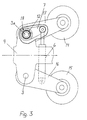
- Figure 5 shows the torsion spring 18 as a reduced view.
- the space 12 between concentric bushes 10 and 11 is filled with an elastic material, such as rubber or the like. This material is fixed in an anti-slip manner onto the inner surface of the bush 10 and onto the outer surface of the bush 11.
- Keys 9 and 13 are used for transmitting the movement to the torsion spring and further.
- the torsion spring can be naturally implemented also in another way with respect to the transmission of the movement; for example, the bush 11 and the axle 3a can be fixed to each other in another way or they can be integrated in one piece, and the movement is transmitted forward by means of the design of the axle instead of the key 13.
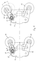
- FIG. 6 The construction shown in Fig. 6 is an example of applying the invention in a case when more than one pair of delimbing blades or feeding means are connected to operate by means of one single actuator.
- the blades of the pairs 1, 1a and 2, 2a of delimbing blades on the same side are each arranged on a common axle 3 and 3a, respectively, mounted pivotally on the frame (not shown in Fig. 6).
- the axles 3 and 3a are also provided with drive arms 7 and 7a of the actuator 6 fixed in an anti-slip manner, for example by a key joint.
- the fixing surfaces can be such that the elastic material cannot move along the surface of the bush.
- the surfaces lying against each other can be toothed.
- the hardness or elasticity of the material of the torsion spring has an effect on the torsion angle caused in the torsion spring by the torsion force, which in this connection means springiness.
- the thickness of the material layer has an effect so that the thicker the material layer, the greater the springiness or elasticity.
Landscapes
- Life Sciences & Earth Sciences (AREA)
- Biodiversity & Conservation Biology (AREA)
- Ecology (AREA)
- Forests & Forestry (AREA)
- Environmental Sciences (AREA)
- Shovels (AREA)
- Harvesting Machines For Specific Crops (AREA)
- Load-Engaging Elements For Cranes (AREA)
- Catching Or Destruction (AREA)
- Orthopedics, Nursing, And Contraception (AREA)
- Harvester Elements (AREA)
- Supports For Plants (AREA)
- Massaging Devices (AREA)
- Percussion Or Vibration Massage (AREA)
- Scissors And Nippers (AREA)
Claims (7)
- Greifer einer Baumerntemaschine, der in einer steuerbaren Art und Weise an einem Kranausleger einer sich über einem Gelände bewegenden Baumerntemaschine befestigbar ist, und mit einem Rahmen (4) der Vorrichtung, zumindest einem Paar von Klemmitteln, wie z. B. Entastungsmittel (1, 2) und/oder Mittel (14, 15) zum Zuführen eines Baumstammes, ebenso wie eine Schneidvorrichtung mit den Mitteln zu deren Antrieb und Steuerung, wobei die Mittel zum Klemmen gegenüber dem Baumstamm über einen Aktuator (6) paarweise federnd im Verhältnis zueinander angeordnet sind, dadurch gekennzeichnet, dass die Klemmmittel, Entastungsmittel (1, 2) und/oder Zuführmittel (14, 15) federnd im Verhältnis zueinander dergestalt angeordnet sind, dass die Bewegung des Aktuators (6) durch einen gesonderten Antriebsarm (7) mittels einer Drehfeder (18) auf einen Schwenkarm (5a) des Paares übertragen wird, wobei der Schwenkarm (5a) über die Drehachse (3a) zwischen dem Antriebsarm (7) und dem Schwenkarm (5a) dergestalt beweglich angeordnet ist, dass ein federndes Element der Drehfeder (18) in Kontakt mit Oberflächen steht, die konzentrisch um die Achse (3a) angeordnet sind und sie sich zusammen mit der Bewegung des Antriebsarmes (7) und des Schwenkarmes (5) dergestalt bewegen, dass die Schwenkbewegung übertragen wird.
- Greifer nach Anspruch 1, dadurch gekennzeichnet, dass die Drehachse zwischen dem Schwenkarm (5a) und dem Rahmen (4) gleichzeitig die Drehachse (3a) zwischen dem Antriebsarm (7) und dem Schwenkarm (5a) bildet.
- Greifer nach Anspruch 1, dadurch gekennzeichnet, dass die Drehachse (3a) zwischen dem Antriebsarm (7) und dem Schwenkarm (5a) in dem Schwenkarm (5a) von der Drehachse des Schwenkarmes und dem Rahmen (4) entfernt angeordnet ist.
- Greifer nach einem der Ansprüche 1 bis 3, dadurch gekennzeichnet, dass das federnde Element der Drehfeder (18) zwischen einer äußeren Oberfläche, die die Achse (3a) in kreisförmiger Art und Weise umgibt, und einer inneren Oberfläche, die diese Oberfläche in einer kreisförmigen Art und Weise umgibt, angeordnet ist.
- Greifer nach Anspruch 4, dadurch gekennzeichnet, dass der Antriebsarm (7) an der äußeren Buchse (10) der Drehfeder befestigt ist, die aus zwei im Verhältnis zu der Drehachse (3a) konzentrischen Buchsen (10, 11) und einem elastischen Material zwischen ihnen besteht und dass die Bewegung von der inneren Buchse (11) der Drehfeder zu dem Schwenkarm (5a) geleitet wird, an welchem die innere Buchse (11) befestigt ist.
- Greifer nach einem der Ansprüche 1 bis 5, dadurch gekennzeichnet, dass der Antriebsarm (7) unmittelbar, in einer festen Art und Weise, auf der Achse (3a) befestigt ist und die Bewegung von der Achse auf den Schwenkarm (5a) über die Drehfeder (18) weitergeleitet wird.
- Greifer nach Anspruch 6, dadurch gekennzeichnet, dass zumindest zwei Klemmittelpaare auf gemeinsamen Achsen (3 und 3a) vorgesehen sind und dass die Antriebsarme (7) des Aktuators (6) fest an den Achsen (3, 3a) befestigt sind und von jedem Paar zumindest eines der Mittel (1, 2a), vorzugsweise diejenigen, die in den Paaren diagonal angeordnet sind, an den Achsen (3 und 3a) über die Drehfeder (18) befestigt sind.
Applications Claiming Priority (3)
| Application Number | Priority Date | Filing Date | Title |
|---|---|---|---|
| FI962874 | 1996-07-17 | ||
| FI962874A FI100576B (fi) | 1996-07-17 | 1996-07-17 | Puunkorjuukoneen koura |
| PCT/FI1997/000449 WO1998003055A1 (en) | 1996-07-17 | 1997-07-17 | Grapple of a tree harvesting machine |
Publications (2)
| Publication Number | Publication Date |
|---|---|
| EP0959663A1 EP0959663A1 (de) | 1999-12-01 |
| EP0959663B1 true EP0959663B1 (de) | 2003-02-12 |
Family
ID=8546402
Family Applications (1)
| Application Number | Title | Priority Date | Filing Date |
|---|---|---|---|
| EP97930540A Expired - Lifetime EP0959663B1 (de) | 1996-07-17 | 1997-07-17 | Griff einer baumerntemaschine |
Country Status (9)
| Country | Link |
|---|---|
| US (1) | US6065513A (de) |
| EP (1) | EP0959663B1 (de) |
| AT (1) | ATE232353T1 (de) |
| AU (1) | AU3445797A (de) |
| CA (1) | CA2258794C (de) |
| DE (1) | DE69719077T2 (de) |
| FI (1) | FI100576B (de) |
| RU (1) | RU2193304C2 (de) |
| WO (1) | WO1998003055A1 (de) |
Families Citing this family (12)
| Publication number | Priority date | Publication date | Assignee | Title |
|---|---|---|---|---|
| FI20001977A0 (fi) * | 2000-09-07 | 2000-09-07 | Lako Oy | Puunkorjuukoneen harvesteripää |
| US7466805B2 (en) * | 2001-05-25 | 2008-12-16 | Grape Technology Group, Inc. | Technique for effectively providing a personalized information assistance service |
| US7934758B2 (en) * | 2007-03-30 | 2011-05-03 | Caterpillar Inc. | Systems and methods for connecting and adapting a grapple assembly |
| SE533023C2 (sv) * | 2008-04-16 | 2010-06-08 | Log Max Ab | Bestämning av grovlek hos en trädstam |
| US7954524B2 (en) * | 2008-12-16 | 2011-06-07 | Caterpillar Forest Products Inc. | Motors and processing units for processing trees |
| US8002004B2 (en) * | 2009-06-12 | 2011-08-23 | Waratah Nz Limited | Delimb arm cam stop |
| US8499803B2 (en) * | 2009-06-12 | 2013-08-06 | Waratah Nz Limited | Protective routing of delimb cylinder hosing |
| EP2629940B1 (de) * | 2010-10-19 | 2017-09-06 | White Puma Pty Limited | Vorrichtung zum durchqueren eines objekts |
| US10486302B2 (en) | 2010-10-19 | 2019-11-26 | White Puma Pty Limited | Device for traversing an object |
| US20150144225A1 (en) * | 2013-11-26 | 2015-05-28 | Deere & Company | Debarking blade arrangement |
| CN110216076A (zh) * | 2019-06-27 | 2019-09-10 | 中信戴卡股份有限公司 | 一种在线加工区别标识装置 |
| CN118923341A (zh) * | 2024-09-13 | 2024-11-12 | 南京林业大学 | 一种用于振动采收机的树干夹持机构 |
Family Cites Families (7)
| Publication number | Priority date | Publication date | Assignee | Title |
|---|---|---|---|---|
| CA872598A (en) * | 1970-03-13 | 1971-06-08 | Zehavi Samuel | Tree feed roll assembly |
| DK162131C (da) * | 1977-03-18 | 1992-02-17 | Jan Eriksson | Apparat til behandling af traestammer |
| SE416027B (sv) * | 1978-03-09 | 1980-11-24 | Jan Eriksson | Anordning vid apparater for behandling av tred |
| SE437145C (sv) * | 1981-10-07 | 1986-11-10 | Jan Eriksson | Anordning for behandling av tred eller tredstammar |
| GB8426857D0 (en) * | 1984-10-24 | 1984-11-28 | Wadkin Public Ltd Co | Feed mechanism |
| SE467102B (sv) * | 1988-04-13 | 1992-05-25 | Jan Eriksson | Drivanordning |
| SE469774B (sv) * | 1989-05-31 | 1993-09-13 | Valmet Logging Ab | Aggregat för trädupparbetning |
-
1996
- 1996-07-17 FI FI962874A patent/FI100576B/fi not_active IP Right Cessation
-
1997
- 1997-07-17 US US09/214,956 patent/US6065513A/en not_active Expired - Fee Related
- 1997-07-17 WO PCT/FI1997/000449 patent/WO1998003055A1/en not_active Ceased
- 1997-07-17 DE DE69719077T patent/DE69719077T2/de not_active Expired - Fee Related
- 1997-07-17 CA CA002258794A patent/CA2258794C/en not_active Expired - Fee Related
- 1997-07-17 EP EP97930540A patent/EP0959663B1/de not_active Expired - Lifetime
- 1997-07-17 AT AT97930540T patent/ATE232353T1/de not_active IP Right Cessation
- 1997-07-17 RU RU99102810/13A patent/RU2193304C2/ru not_active IP Right Cessation
- 1997-07-17 AU AU34457/97A patent/AU3445797A/en not_active Abandoned
Also Published As
| Publication number | Publication date |
|---|---|
| CA2258794C (en) | 2005-01-25 |
| AU3445797A (en) | 1998-02-10 |
| ATE232353T1 (de) | 2003-02-15 |
| WO1998003055A1 (en) | 1998-01-29 |
| DE69719077T2 (de) | 2003-10-30 |
| RU2193304C2 (ru) | 2002-11-27 |
| CA2258794A1 (en) | 1998-01-29 |
| US6065513A (en) | 2000-05-23 |
| EP0959663A1 (de) | 1999-12-01 |
| FI100576B (fi) | 1998-01-15 |
| FI962874A0 (fi) | 1996-07-17 |
| DE69719077D1 (de) | 2003-03-20 |
Similar Documents
| Publication | Publication Date | Title |
|---|---|---|
| EP0959663B1 (de) | Griff einer baumerntemaschine | |
| EP3595961B1 (de) | Federungsvorrichtung für kettenfahrzeuge | |
| RU2297756C2 (ru) | Колесная опора сельскохозяйственной машины | |
| FI126750B (fi) | Metsäkone ja telayksikkö | |
| SE537571C2 (sv) | Anordning för att anpassa marktrycket hos ett terränggåendemotorfordon och ett terränggående motorfordon utrustad med en sådan anordning | |
| US7086214B2 (en) | Mower suspension | |
| EP0997062B1 (de) | Landmaschine | |
| CA2748905A1 (en) | A feller device for felling and delimbing of tree trunks, and a delimbing blade | |
| US6622761B1 (en) | Delimbing apparatus | |
| US6962359B2 (en) | Arrangement for the suspension of wheels in a working machine | |
| US6345651B1 (en) | Delimbing and cutting head of a harvesting machine | |
| RU99102810A (ru) | Захват лесозаготовительной машины | |
| US6202719B1 (en) | Timber harvester and a feeder device for it | |
| JP2000312519A (ja) | 切断した作物の処理装置と、この処理装置を用いる草刈り機 | |
| EP0534937B1 (de) | Antriebs- und gelenkanordnung zwischen einem geländefahrzeug und einem anhänger | |
| US3719217A (en) | Method and apparatus for delimbing a tree | |
| WO2002019801A1 (en) | Harvester head in a harvesting machine | |
| EP3769611B1 (de) | Holzbearbeitungsvorrichtung | |
| WO2002021906A1 (en) | Link mechanism for harvesting head | |
| FI70505B (fi) | Traedbehandlingsanordning | |
| FI103653B (fi) | Laitteisto puuntyöstöön | |
| EP4406394A2 (de) | Gezogener mäher mit stabilitätskontrolle | |
| EP0973373B1 (de) | An einer maschine befestigte einrichtung zum fällen,zersägen und ausästen von bäumen | |
| FI84445B (fi) | Frammatningsanordning foer traed vid en flerfunktionsdel av en skogsmaskin. | |
| FI121260B (fi) | Harvesterin kääntölaitteisto |
Legal Events
| Date | Code | Title | Description |
|---|---|---|---|
| PUAI | Public reference made under article 153(3) epc to a published international application that has entered the european phase |
Free format text: ORIGINAL CODE: 0009012 |
|
| 17P | Request for examination filed |
Effective date: 19981202 |
|
| AK | Designated contracting states |
Kind code of ref document: A1 Designated state(s): AT CH DE ES FR GB IT LI PT SE |
|
| GRAH | Despatch of communication of intention to grant a patent |
Free format text: ORIGINAL CODE: EPIDOS IGRA |
|
| GRAH | Despatch of communication of intention to grant a patent |
Free format text: ORIGINAL CODE: EPIDOS IGRA |
|
| GRAA | (expected) grant |
Free format text: ORIGINAL CODE: 0009210 |
|
| AK | Designated contracting states |
Designated state(s): AT CH DE ES FR GB IT LI PT SE |
|
| PG25 | Lapsed in a contracting state [announced via postgrant information from national office to epo] |
Ref country code: LI Free format text: LAPSE BECAUSE OF FAILURE TO SUBMIT A TRANSLATION OF THE DESCRIPTION OR TO PAY THE FEE WITHIN THE PRESCRIBED TIME-LIMIT Effective date: 20030212 Ref country code: IT Free format text: LAPSE BECAUSE OF FAILURE TO SUBMIT A TRANSLATION OF THE DESCRIPTION OR TO PAY THE FEE WITHIN THE PRESCRIBED TIME-LIMIT;WARNING: LAPSES OF ITALIAN PATENTS WITH EFFECTIVE DATE BEFORE 2007 MAY HAVE OCCURRED AT ANY TIME BEFORE 2007. THE CORRECT EFFECTIVE DATE MAY BE DIFFERENT FROM THE ONE RECORDED. Effective date: 20030212 Ref country code: FR Free format text: LAPSE BECAUSE OF FAILURE TO SUBMIT A TRANSLATION OF THE DESCRIPTION OR TO PAY THE FEE WITHIN THE PRESCRIBED TIME-LIMIT Effective date: 20030212 Ref country code: CH Free format text: LAPSE BECAUSE OF FAILURE TO SUBMIT A TRANSLATION OF THE DESCRIPTION OR TO PAY THE FEE WITHIN THE PRESCRIBED TIME-LIMIT Effective date: 20030212 Ref country code: AT Free format text: LAPSE BECAUSE OF FAILURE TO SUBMIT A TRANSLATION OF THE DESCRIPTION OR TO PAY THE FEE WITHIN THE PRESCRIBED TIME-LIMIT Effective date: 20030212 |
|
| REG | Reference to a national code |
Ref country code: GB Ref legal event code: FG4D |
|
| REG | Reference to a national code |
Ref country code: CH Ref legal event code: EP |
|
| REF | Corresponds to: |
Ref document number: 69719077 Country of ref document: DE Date of ref document: 20030320 Kind code of ref document: P |
|
| PG25 | Lapsed in a contracting state [announced via postgrant information from national office to epo] |
Ref country code: PT Free format text: LAPSE BECAUSE OF FAILURE TO SUBMIT A TRANSLATION OF THE DESCRIPTION OR TO PAY THE FEE WITHIN THE PRESCRIBED TIME-LIMIT Effective date: 20030512 |
|
| REG | Reference to a national code |
Ref country code: SE Ref legal event code: TRGR |
|
| PG25 | Lapsed in a contracting state [announced via postgrant information from national office to epo] |
Ref country code: GB Free format text: LAPSE BECAUSE OF NON-PAYMENT OF DUE FEES Effective date: 20030717 |
|
| PG25 | Lapsed in a contracting state [announced via postgrant information from national office to epo] |
Ref country code: ES Free format text: LAPSE BECAUSE OF FAILURE TO SUBMIT A TRANSLATION OF THE DESCRIPTION OR TO PAY THE FEE WITHIN THE PRESCRIBED TIME-LIMIT Effective date: 20030828 |
|
| REG | Reference to a national code |
Ref country code: CH Ref legal event code: PL |
|
| PLBE | No opposition filed within time limit |
Free format text: ORIGINAL CODE: 0009261 |
|
| STAA | Information on the status of an ep patent application or granted ep patent |
Free format text: STATUS: NO OPPOSITION FILED WITHIN TIME LIMIT |
|
| EN | Fr: translation not filed | ||
| 26N | No opposition filed |
Effective date: 20031113 |
|
| GBPC | Gb: european patent ceased through non-payment of renewal fee |
Effective date: 20030717 |
|
| PGFP | Annual fee paid to national office [announced via postgrant information from national office to epo] |
Ref country code: DE Payment date: 20060620 Year of fee payment: 10 |
|
| PG25 | Lapsed in a contracting state [announced via postgrant information from national office to epo] |
Ref country code: DE Free format text: LAPSE BECAUSE OF NON-PAYMENT OF DUE FEES Effective date: 20080201 |
|
| PGFP | Annual fee paid to national office [announced via postgrant information from national office to epo] |
Ref country code: SE Payment date: 20110727 Year of fee payment: 15 |
|
| REG | Reference to a national code |
Ref country code: SE Ref legal event code: EUG |
|
| PG25 | Lapsed in a contracting state [announced via postgrant information from national office to epo] |
Ref country code: SE Free format text: LAPSE BECAUSE OF NON-PAYMENT OF DUE FEES Effective date: 20120718 |