EP0959453A2 - Aktive Geräuschunterdrückung für lärmabstrahlende Flächen - Google Patents
Aktive Geräuschunterdrückung für lärmabstrahlende Flächen Download PDFInfo
- Publication number
- EP0959453A2 EP0959453A2 EP99109724A EP99109724A EP0959453A2 EP 0959453 A2 EP0959453 A2 EP 0959453A2 EP 99109724 A EP99109724 A EP 99109724A EP 99109724 A EP99109724 A EP 99109724A EP 0959453 A2 EP0959453 A2 EP 0959453A2
- Authority
- EP
- European Patent Office
- Prior art keywords
- active noise
- noise suppression
- axis
- sensors
- noise
- Prior art date
- Legal status (The legal status is an assumption and is not a legal conclusion. Google has not performed a legal analysis and makes no representation as to the accuracy of the status listed.)
- Granted
Links
- 230000001629 suppression Effects 0.000 claims abstract description 12
- 230000001133 acceleration Effects 0.000 claims description 5
- 239000011888 foil Substances 0.000 description 7
- 230000005855 radiation Effects 0.000 description 6
- 239000002033 PVDF binder Substances 0.000 description 2
- 239000011159 matrix material Substances 0.000 description 2
- 238000000034 method Methods 0.000 description 2
- 230000010355 oscillation Effects 0.000 description 2
- 229920002981 polyvinylidene fluoride Polymers 0.000 description 2
- 238000002485 combustion reaction Methods 0.000 description 1
- 230000005284 excitation Effects 0.000 description 1
- 230000010354 integration Effects 0.000 description 1
- 238000004519 manufacturing process Methods 0.000 description 1
Images
Classifications
-
- G—PHYSICS
- G10—MUSICAL INSTRUMENTS; ACOUSTICS
- G10K—SOUND-PRODUCING DEVICES; METHODS OR DEVICES FOR PROTECTING AGAINST, OR FOR DAMPING, NOISE OR OTHER ACOUSTIC WAVES IN GENERAL; ACOUSTICS NOT OTHERWISE PROVIDED FOR
- G10K11/00—Methods or devices for transmitting, conducting or directing sound in general; Methods or devices for protecting against, or for damping, noise or other acoustic waves in general
- G10K11/16—Methods or devices for protecting against, or for damping, noise or other acoustic waves in general
- G10K11/175—Methods or devices for protecting against, or for damping, noise or other acoustic waves in general using interference effects; Masking sound
- G10K11/178—Methods or devices for protecting against, or for damping, noise or other acoustic waves in general using interference effects; Masking sound by electro-acoustically regenerating the original acoustic waves in anti-phase
- G10K11/1785—Methods, e.g. algorithms; Devices
- G10K11/17857—Geometric disposition, e.g. placement of microphones
-
- G—PHYSICS
- G10—MUSICAL INSTRUMENTS; ACOUSTICS
- G10K—SOUND-PRODUCING DEVICES; METHODS OR DEVICES FOR PROTECTING AGAINST, OR FOR DAMPING, NOISE OR OTHER ACOUSTIC WAVES IN GENERAL; ACOUSTICS NOT OTHERWISE PROVIDED FOR
- G10K11/00—Methods or devices for transmitting, conducting or directing sound in general; Methods or devices for protecting against, or for damping, noise or other acoustic waves in general
- G10K11/16—Methods or devices for protecting against, or for damping, noise or other acoustic waves in general
- G10K11/175—Methods or devices for protecting against, or for damping, noise or other acoustic waves in general using interference effects; Masking sound
- G10K11/178—Methods or devices for protecting against, or for damping, noise or other acoustic waves in general using interference effects; Masking sound by electro-acoustically regenerating the original acoustic waves in anti-phase
- G10K11/1785—Methods, e.g. algorithms; Devices
-
- G—PHYSICS
- G10—MUSICAL INSTRUMENTS; ACOUSTICS
- G10K—SOUND-PRODUCING DEVICES; METHODS OR DEVICES FOR PROTECTING AGAINST, OR FOR DAMPING, NOISE OR OTHER ACOUSTIC WAVES IN GENERAL; ACOUSTICS NOT OTHERWISE PROVIDED FOR
- G10K11/00—Methods or devices for transmitting, conducting or directing sound in general; Methods or devices for protecting against, or for damping, noise or other acoustic waves in general
- G10K11/16—Methods or devices for protecting against, or for damping, noise or other acoustic waves in general
- G10K11/175—Methods or devices for protecting against, or for damping, noise or other acoustic waves in general using interference effects; Masking sound
- G10K11/178—Methods or devices for protecting against, or for damping, noise or other acoustic waves in general using interference effects; Masking sound by electro-acoustically regenerating the original acoustic waves in anti-phase
- G10K11/1787—General system configurations
- G10K11/17879—General system configurations using both a reference signal and an error signal
-
- G—PHYSICS
- G10—MUSICAL INSTRUMENTS; ACOUSTICS
- G10K—SOUND-PRODUCING DEVICES; METHODS OR DEVICES FOR PROTECTING AGAINST, OR FOR DAMPING, NOISE OR OTHER ACOUSTIC WAVES IN GENERAL; ACOUSTICS NOT OTHERWISE PROVIDED FOR
- G10K2210/00—Details of active noise control [ANC] covered by G10K11/178 but not provided for in any of its subgroups
- G10K2210/10—Applications
- G10K2210/128—Vehicles
-
- G—PHYSICS
- G10—MUSICAL INSTRUMENTS; ACOUSTICS
- G10K—SOUND-PRODUCING DEVICES; METHODS OR DEVICES FOR PROTECTING AGAINST, OR FOR DAMPING, NOISE OR OTHER ACOUSTIC WAVES IN GENERAL; ACOUSTICS NOT OTHERWISE PROVIDED FOR
- G10K2210/00—Details of active noise control [ANC] covered by G10K11/178 but not provided for in any of its subgroups
- G10K2210/10—Applications
- G10K2210/129—Vibration, e.g. instead of, or in addition to, acoustic noise
- G10K2210/1291—Anti-Vibration-Control, e.g. reducing vibrations in panels or beams
-
- G—PHYSICS
- G10—MUSICAL INSTRUMENTS; ACOUSTICS
- G10K—SOUND-PRODUCING DEVICES; METHODS OR DEVICES FOR PROTECTING AGAINST, OR FOR DAMPING, NOISE OR OTHER ACOUSTIC WAVES IN GENERAL; ACOUSTICS NOT OTHERWISE PROVIDED FOR
- G10K2210/00—Details of active noise control [ANC] covered by G10K11/178 but not provided for in any of its subgroups
- G10K2210/30—Means
- G10K2210/321—Physical
- G10K2210/3229—Transducers
- G10K2210/32291—Plates or thin films, e.g. PVDF
Definitions
- the invention relates to active noise suppression for a noise-emitting Surface with at least one fast sensor connected to the surface and at least one that can be controlled by the signal of the fast sensor, actuator acting on the surface.
- Such a system for reducing the sound radiation from a flat surface is described, for example, by ME Johnson and SJ Elliott in Journal of Acoustic Society of America, 98 (4), Oct. 1995 under the title Active Control of Sound Radiation Using Volume Velocity Cancellation ".
- a fast sensor is used which, like the actuator, extends over the entire surface and only detects odd-numbered vibration modes, in particular the basic mode (1,1) and these vibrations by means of the actuator If the noise-radiating surface vibrates with higher vibration modes in which even one component is an even number, for example, (1,2), (2,3), etc. modes, such a surface-integrating sensor does not provide any Output signal more, since the integration over all oscillation peaks and valleys results in the sum signal 0.
- the invention uses axis-selective integrating fast sensors, which in the simplest case consist of strip-shaped Piezo foils are made. As soon as one along one axis such a sensor occupies a vibration mode with a odd component occurs, is the sum signal at this sensor no longer 0, so that an appropriately controlled actuator of this vibration mode can counteract.
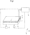
- a plate 1 which can be, for example, a structural or body part and which are a source of interference 2, e.g. B. an internal combustion engine excited to vibrate is applied two piezoelectric foils 3 and 4 one above the other.
- the piezoelectric For example, slides 3 and 4 consist of stretched PVDF, which due to their manufacturing process is unidirectional piezoelectric Have properties.
- the two foils 3 and 4 are arranged one above the other that their preferred piezoelectric directions represented by arrows are oriented perpendicular to each other in the plate plane.
- the embodiment is thus the film 3 for deflections of the plate surface sensitive in the x direction and the film 4 for deflections in y direction.
- the voltage signals generated by the foils 3 and 4 are fed to a controller 5, which processes the signals according to known methods and controls an actuator 6.
- the actuator 6 can act on the plate 1 either in a punctiform or area-like manner and in such a way that vibration-induced deflections of the plate are counteracted.
- Feed Forward control, the vibration signals of the interference source 2 can be detected and fed to the controller.
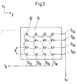
- the speed of a plate 31 is detected point by point by means of individual sensors 32 which are distributed in a matrix over the surface of the plate 31.
- acceleration sensors which are glued to the surface of the plate 31 and which are electrically connected to one another in rows and columns are suitable.
- the sensors in the upper line then deliver, for example, a first sum signal S 1x , those in the second line the signal S 2x and so on;
- the sensors of the left column supply the sum signal S 1y , those of the next column the sum signal S 2y etc.
- the row or column spacing of the measuring grid constructed from the acceleration sensors 32 must be adapted to the structure and to the frequency range in which noise reduction is desired. In order to resolve the highest possible mode orders, the distance d should be less than a quarter of the structure wavelength ⁇ of the highest mode.
- appropriately small-sized strain gauges, piezoceramics or piezofilms can also be used.
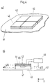
- each attachment element consists of a hard one Shell 42.1, which is provided with side walls 42.2, which in turn on the Place plate 41 and, together with shell 42.1, a cavity 43 form.
- the shell 42.1 is in accordance with the exemplary embodiments 1, 2 or 3 are equipped with axis-selective fast sensors 44 and 45, whose signals are fed to a controller 46. This controls an actuator 47, which acts centrally on the shell 42.1.
- Such attachment elements are particularly suitable for noise suppression of complex sound-emitting structures in which the vibration and radiation behavior can only be determined with difficulty.
- the vibrations and attachment elements the emitted sound of the actually vibrating structure (plate 41) in turn stimulated.
- the active system integrated in the front elements reduces their noise radiation and thus the sound radiation of the structure self.
Landscapes
- Physics & Mathematics (AREA)
- Engineering & Computer Science (AREA)
- Acoustics & Sound (AREA)
- Multimedia (AREA)
- Soundproofing, Sound Blocking, And Sound Damping (AREA)
- Measurement Of Mechanical Vibrations Or Ultrasonic Waves (AREA)
- Exhaust Silencers (AREA)
Abstract
Description
- Fig. 1
- ein aktives System zur Geräuschunterdrückung mit zwei achsenselektiven Schnellesensoren
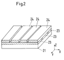
- Fig. 2
- streifenförmige, achsenselektive Schnellesensoren auf einer Struktur
- Fig. 3
- matrixförmig angeordnete Schnellesensoren auf einer Struktur und
- Fig. 4a und 4b
- aktive Vorsatzelemente zur Geräuschunterdrückung.
Claims (6)
- Aktive Geräuschunterdrückung für eine lärmabstrahlende Fläche mit mindestens einem mit der Fläche verbundenen Schnellesensor und mindestens einem, durch das Signal des Schnellesensors ansteuerbaren, auf die Fläche wirkenden Aktuator, gekennzeichnet durch mindestens zwei achsenselektiv integrierende Schnellesensoren (3, 4), welche Schwingungen der Fläche (1) in mindestens zwei, im wesentlichen orthogonale Richtungen (x, y) erfassen.
- Aktive Geräuschunterdrückung nach Anspruch 1, dadurch gekennzeichnet, daß der achsenselektiv integrierende Schnellesensor (23, 24) mindestens ein streifenförmiges Piezoelement aufweist.
- Aktive Geräuschunterdrückung nach Anspruch 1 oder 2, dadurch gekennzeichnet, daß der achsenselektiv integrierende Schnellesensor (23, 24) mehrere parallel nebeneinander angeordnete und elektrisch parallel geschaltete streifenförmige Piezoelemente aufweist.
- Aktive Geräuschunterdrückung nach einem der Ansprüche 1 bis 3, dadurch gekennzeichnet, daß der achsenselektiv integrierende Schnellesensor mehrere punktförmige, matrixförmig sowohl auf der Fläche (31) angeordnete, als auch elektrisch verschaltete Beschleunigungs- oder Deformationsaufnehmer (32) aufweist, wobei zumindest für je eine Zeile und je eine Spalte mittels der Beschleunigungs- oder Deformationsaufnehmer ein Summensignal (S1x, S2x, ...; S1y, S2y, ...) gebildet wird.
- Aktive Geräuschunterdrückung nach einem der Ansprüche 1 bis 4, dadurch gekennzeichnet, daß die Schnellesensoren (44, 45) und der Aktuator (47) auf einer harten Schale (42.1) angeordnet sind, welche über Seitenwände (42.2)unter Bildung eines Hohlraumes (43) mit der lärmabstrahlenden Fläche (41) verbindbar ist.
- Aktive Geräuschunterdrückung nach Anspruch 5, dadurch gekennzeichnet, daß mehrere nebeneinander angeordnete Schalen (42.1) ein flächen deckendes Muster bilden.
Applications Claiming Priority (2)
| Application Number | Priority Date | Filing Date | Title |
|---|---|---|---|
| DE19822582A DE19822582B4 (de) | 1998-05-20 | 1998-05-20 | Aktive Geräuschunterdrückung für lärmabstrahlende Flächen |
| DE19822582 | 1998-05-20 |
Publications (3)
| Publication Number | Publication Date |
|---|---|
| EP0959453A2 true EP0959453A2 (de) | 1999-11-24 |
| EP0959453A3 EP0959453A3 (de) | 2001-11-21 |
| EP0959453B1 EP0959453B1 (de) | 2004-01-07 |
Family
ID=7868372
Family Applications (1)
| Application Number | Title | Priority Date | Filing Date |
|---|---|---|---|
| EP99109724A Expired - Lifetime EP0959453B1 (de) | 1998-05-20 | 1999-05-18 | Aktives Geräuschunterdrückungssystem für lärmabstrahlende Flächen |
Country Status (3)
| Country | Link |
|---|---|
| US (1) | US6178246B1 (de) |
| EP (1) | EP0959453B1 (de) |
| DE (2) | DE19822582B4 (de) |
Cited By (2)
| Publication number | Priority date | Publication date | Assignee | Title |
|---|---|---|---|---|
| WO2008046815A3 (de) * | 2006-10-16 | 2009-10-29 | BSH Bosch und Siemens Hausgeräte GmbH | Geräuschveränderungsvorrichtung |
| CN115064083A (zh) * | 2018-09-20 | 2022-09-16 | 乐金显示有限公司 | 显示设备和包括该显示设备的计算设备 |
Families Citing this family (22)
| Publication number | Priority date | Publication date | Assignee | Title |
|---|---|---|---|---|
| DE10117704C2 (de) * | 2001-04-09 | 2002-08-01 | Hoergeraete Kind Gmbh U Co Kg | Kapselgehörschützer mit aktiver Schalldruckkompensation |
| US20030047395A1 (en) * | 2001-09-11 | 2003-03-13 | Patton Mark E. | Control system for vibration employing piezoelectric strain actuators |
| US6609985B2 (en) | 2001-11-07 | 2003-08-26 | Borgwarner Inc. | Tensioner with vibrational damping |
| SE524284C2 (sv) * | 2002-04-18 | 2004-07-20 | A2 Acoustics Ab | Anordning för att driva ett membran inrättat i en öppning till ett utrymme samt fordon innefattande en anordning för att driva ett membran inrättat i en öppning hos fordonet |
| US7330583B2 (en) * | 2002-08-19 | 2008-02-12 | Photon Dynamics, Inc. | Integrated visual imaging and electronic sensing inspection systems |
| NL1022647C2 (nl) * | 2003-02-11 | 2004-08-12 | Tno | Inrichting voor het actief reduceren van geluidstransmissie, alsmede een paneel omvattende een dergelijke inrichting. |
| DE102004019592A1 (de) * | 2004-04-22 | 2005-09-01 | Siemens Ag | Schalldämmungsvorrichtung |
| US8054984B2 (en) * | 2006-10-16 | 2011-11-08 | Bsh Home Appliances Corporation | Sound altering apparatus |
| US8059827B2 (en) * | 2006-10-16 | 2011-11-15 | Bsh Home Appliances Corporation | Noise reduction apparatus |
| JP5227263B2 (ja) * | 2008-06-03 | 2013-07-03 | パナソニック株式会社 | 能動騒音低減装置及びシステム |
| FR2960587B1 (fr) | 2010-05-31 | 2017-12-01 | Somfy Sas | Dispositif de rigidification et caisson de store equipe d'un tel dispositif |
| DE102010043108A1 (de) * | 2010-10-29 | 2012-05-03 | Robert Bosch Gmbh | Piezoelektrischer Teilflächen-Schallwandler |
| BR112014027723A2 (pt) | 2012-05-11 | 2017-06-27 | 3M Innovative Properties Co | sensor bioacústico com controle de vibração de ruído |
| CN105247335A (zh) * | 2012-09-24 | 2016-01-13 | 积水化学工业株式会社 | 泄露检测器、泄露检测方法及配管网的监视装置 |
| DE102013007481B4 (de) | 2013-04-29 | 2014-12-04 | DELUXE MCB UG (haftungsbeschränkt) | Vorrichtung zur Schallreduzierung in Gasträumen |
| US9200943B2 (en) | 2013-07-17 | 2015-12-01 | GM Global Technology Operations LLC | Acoustic sensing system for a motor vehicle |
| US11335312B2 (en) | 2016-11-08 | 2022-05-17 | Andersen Corporation | Active noise cancellation systems and methods |
| EP3788619A1 (de) | 2018-05-04 | 2021-03-10 | Andersen Corporation | Anvisierung von mehrbandfrequenz zur geräuschdämpfung |
| DE102018219644A1 (de) * | 2018-11-16 | 2020-05-20 | Zf Friedrichshafen Ag | Aktive Reduktion von Schallemissionen an einem Kraftfahrzeug |
| CN112987508B (zh) * | 2021-03-04 | 2022-09-30 | 长鑫存储技术有限公司 | 振动衰减结构及曝光装置 |
| DE102021206170A1 (de) | 2021-06-16 | 2022-12-22 | Volkswagen Aktiengesellschaft | Gehäusekomponente eines Leistungselektronikgehäuses mit Schwingungsaktor |
| DE102021126180A1 (de) | 2021-10-08 | 2023-04-13 | BH Holding GmbH | Verfahren zur aktiven Geräuschunterdrückung in Innenräumen |
Family Cites Families (8)
| Publication number | Priority date | Publication date | Assignee | Title |
|---|---|---|---|---|
| DE3236098A1 (de) * | 1982-09-29 | 1984-03-29 | Siemens AG, 1000 Berlin und 8000 München | Druckwandleranordnung, insbesondere fuer industrieroboter |
| US5115472A (en) * | 1988-10-07 | 1992-05-19 | Park Kyung T | Electroacoustic novelties |
| DE3834853C2 (de) * | 1988-10-13 | 1999-12-02 | Bayerische Motoren Werke Ag | Anordnung zur Verminderung des Geräuschpegels im Innenraum eines Kraftfahrzeugs |
| JP3320842B2 (ja) * | 1992-07-06 | 2002-09-03 | マツダ株式会社 | 車両の振動低減装置 |
| US5410607A (en) * | 1993-09-24 | 1995-04-25 | Sri International | Method and apparatus for reducing noise radiated from a complex vibrating surface |
| US5415522A (en) * | 1993-11-01 | 1995-05-16 | General Electric Company | Active noise control using noise source having adaptive resonant frequency tuning through stress variation |
| US5812684A (en) * | 1995-07-05 | 1998-09-22 | Ford Global Technologies, Inc. | Passenger compartment noise attenuation apparatus for use in a motor vehicle |
| US6031917A (en) * | 1997-06-06 | 2000-02-29 | Mcdonnell Douglas Corporation | Active noise control using blocked mode approach |
-
1998
- 1998-05-20 DE DE19822582A patent/DE19822582B4/de not_active Expired - Fee Related
-
1999
- 1999-05-18 EP EP99109724A patent/EP0959453B1/de not_active Expired - Lifetime
- 1999-05-18 DE DE59908223T patent/DE59908223D1/de not_active Expired - Lifetime
- 1999-05-20 US US09/315,770 patent/US6178246B1/en not_active Expired - Lifetime
Cited By (3)
| Publication number | Priority date | Publication date | Assignee | Title |
|---|---|---|---|---|
| WO2008046815A3 (de) * | 2006-10-16 | 2009-10-29 | BSH Bosch und Siemens Hausgeräte GmbH | Geräuschveränderungsvorrichtung |
| CN115064083A (zh) * | 2018-09-20 | 2022-09-16 | 乐金显示有限公司 | 显示设备和包括该显示设备的计算设备 |
| CN115064083B (zh) * | 2018-09-20 | 2024-03-26 | 乐金显示有限公司 | 显示设备和包括该显示设备的计算设备 |
Also Published As
| Publication number | Publication date |
|---|---|
| DE19822582B4 (de) | 2004-02-12 |
| US6178246B1 (en) | 2001-01-23 |
| EP0959453B1 (de) | 2004-01-07 |
| EP0959453A3 (de) | 2001-11-21 |
| DE59908223D1 (de) | 2004-02-12 |
| DE19822582A1 (de) | 1999-11-25 |
Similar Documents
| Publication | Publication Date | Title |
|---|---|---|
| DE19822582B4 (de) | Aktive Geräuschunterdrückung für lärmabstrahlende Flächen | |
| DE3731196C2 (de) | ||
| DE102006005048B4 (de) | Ultraschallsensor mit Sendeeinrichtung und Empfangseinrichtung für Ultraschallwellen | |
| DE3344910C2 (de) | Anordnung zum aktiven Dämpfen von Schallwellen | |
| DE3733776A1 (de) | Ultraschallsonde | |
| DE19735155B4 (de) | Beschleunigungssensor | |
| DE102008040911A1 (de) | Verfahren zum Senden einer Ultraschallwelle und Vorrichtung zum Senden einer Ultraschallwelle | |
| DE69712471T2 (de) | Akustisches element und verfahren zur tonverarbeitung | |
| EP1059620B1 (de) | Piezo-Effekt-basiertes Sicherheitsmerkmal an Wert- und Sicherheitsdokumenten und dazugehöriges Nachweisverfahren | |
| DE102014225010B4 (de) | Mikrofon und Verfahren zur Herstellung desselben | |
| DE69421503T2 (de) | Piezoelektrischer Sensor und Koordinateneingabegerät | |
| DE112020002082B4 (de) | Ultraschallsensor | |
| DE3443869A1 (de) | Wandleranordnung fuer hydrophone | |
| DE69821074T2 (de) | Composite ultrasound transducer | |
| DE10047942B4 (de) | Sensorarray, Verfahren zum Herstellen eines Sensorarrays und Verwendung eines Sensorarrays | |
| WO2020229696A1 (de) | Piezoelektrische vorrichtung | |
| DE202012004305U1 (de) | Vorrichtung zum Detektieren einer Kante einer Materialbahn | |
| EP3329473B1 (de) | Einrichtung und verfahren zur untersuchung von wertdokumenten und / oder des transports von wertdokumenten mittels ultraschall | |
| DE3215242A1 (de) | Ultraschallkopf | |
| EP4107543B1 (de) | Wasserschallwandler | |
| DE102008011285A1 (de) | Aktiver Schallblocker | |
| EP1145772A2 (de) | Ultraschallwandler und Verfahren zur Herstellung eines Ultraschallwandlers | |
| DE3709533C2 (de) | ||
| DE4208043A1 (de) | Verfahren zur messung einer beschleunigung, beschleunigungssensor und verfahren zu dessen herstellung | |
| DE112019006369T5 (de) | Piezoelektrischer Wandler |
Legal Events
| Date | Code | Title | Description |
|---|---|---|---|
| PUAI | Public reference made under article 153(3) epc to a published international application that has entered the european phase |
Free format text: ORIGINAL CODE: 0009012 |
|
| AK | Designated contracting states |
Kind code of ref document: A2 Designated state(s): AT BE CH CY DE DK ES FI FR GB GR IE IT LI LU MC NL PT SE Kind code of ref document: A2 Designated state(s): DE FR GB IT |
|
| AX | Request for extension of the european patent |
Free format text: AL;LT;LV;MK;RO;SI |
|
| RIN1 | Information on inventor provided before grant (corrected) |
Inventor name: SCHMIDTS, KLAUS Inventor name: MAIER, RUDOLF Inventor name: BEBESEL, MARIUS |
|
| PUAL | Search report despatched |
Free format text: ORIGINAL CODE: 0009013 |
|
| AK | Designated contracting states |
Kind code of ref document: A3 Designated state(s): AT BE CH CY DE DK ES FI FR GB GR IE IT LI LU MC NL PT SE |
|
| AX | Request for extension of the european patent |
Free format text: AL;LT;LV;MK;RO;SI |
|
| 17P | Request for examination filed |
Effective date: 20011116 |
|
| RAP1 | Party data changed (applicant data changed or rights of an application transferred) |
Owner name: EADS DEUTSCHLAND GMBH |
|
| 17Q | First examination report despatched |
Effective date: 20020417 |
|
| AKX | Designation fees paid |
Free format text: DE FR GB IT |
|
| GRAP | Despatch of communication of intention to grant a patent |
Free format text: ORIGINAL CODE: EPIDOSNIGR1 |
|
| RAP1 | Party data changed (applicant data changed or rights of an application transferred) |
Owner name: EADS DEUTSCHLAND GMBH |
|
| GRAS | Grant fee paid |
Free format text: ORIGINAL CODE: EPIDOSNIGR3 |
|
| GRAA | (expected) grant |
Free format text: ORIGINAL CODE: 0009210 |
|
| AK | Designated contracting states |
Kind code of ref document: B1 Designated state(s): DE FR GB IT |
|
| REG | Reference to a national code |
Ref country code: GB Ref legal event code: FG4D Free format text: NOT ENGLISH |
|
| REF | Corresponds to: |
Ref document number: 59908223 Country of ref document: DE Date of ref document: 20040212 Kind code of ref document: P |
|
| GBT | Gb: translation of ep patent filed (gb section 77(6)(a)/1977) |
Effective date: 20040129 |
|
| ET | Fr: translation filed | ||
| PLBE | No opposition filed within time limit |
Free format text: ORIGINAL CODE: 0009261 |
|
| STAA | Information on the status of an ep patent application or granted ep patent |
Free format text: STATUS: NO OPPOSITION FILED WITHIN TIME LIMIT |
|
| 26N | No opposition filed |
Effective date: 20041008 |
|
| REG | Reference to a national code |
Ref country code: FR Ref legal event code: TP Owner name: AIRBUS OPERATIONS GMBH, DE Effective date: 20130417 |
|
| PGFP | Annual fee paid to national office [announced via postgrant information from national office to epo] |
Ref country code: DE Payment date: 20130522 Year of fee payment: 15 Ref country code: GB Payment date: 20130521 Year of fee payment: 15 |
|
| PGFP | Annual fee paid to national office [announced via postgrant information from national office to epo] |
Ref country code: IT Payment date: 20130527 Year of fee payment: 15 Ref country code: FR Payment date: 20130603 Year of fee payment: 15 |
|
| REG | Reference to a national code |
Ref country code: DE Ref legal event code: R119 Ref document number: 59908223 Country of ref document: DE |
|
| GBPC | Gb: european patent ceased through non-payment of renewal fee |
Effective date: 20140518 |
|
| REG | Reference to a national code |
Ref country code: FR Ref legal event code: ST Effective date: 20150130 |
|
| REG | Reference to a national code |
Ref country code: DE Ref legal event code: R119 Ref document number: 59908223 Country of ref document: DE Effective date: 20141202 |
|
| PG25 | Lapsed in a contracting state [announced via postgrant information from national office to epo] |
Ref country code: IT Free format text: LAPSE BECAUSE OF NON-PAYMENT OF DUE FEES Effective date: 20140518 Ref country code: DE Free format text: LAPSE BECAUSE OF NON-PAYMENT OF DUE FEES Effective date: 20141202 |
|
| PG25 | Lapsed in a contracting state [announced via postgrant information from national office to epo] |
Ref country code: FR Free format text: LAPSE BECAUSE OF NON-PAYMENT OF DUE FEES Effective date: 20140602 Ref country code: GB Free format text: LAPSE BECAUSE OF NON-PAYMENT OF DUE FEES Effective date: 20140518 |