EP0959349A2 - Streuflusssonde zur zerstörungsfreien Prüfung von langgestreckten, rotationssymmetrischen Körpern - Google Patents
Streuflusssonde zur zerstörungsfreien Prüfung von langgestreckten, rotationssymmetrischen Körpern Download PDFInfo
- Publication number
- EP0959349A2 EP0959349A2 EP99250130A EP99250130A EP0959349A2 EP 0959349 A2 EP0959349 A2 EP 0959349A2 EP 99250130 A EP99250130 A EP 99250130A EP 99250130 A EP99250130 A EP 99250130A EP 0959349 A2 EP0959349 A2 EP 0959349A2
- Authority
- EP
- European Patent Office
- Prior art keywords
- circuit board
- printed
- connector
- coils
- socket
- Prior art date
- Legal status (The legal status is an assumption and is not a legal conclusion. Google has not performed a legal analysis and makes no representation as to the accuracy of the status listed.)
- Withdrawn
Links
- 239000000523 sample Substances 0.000 title claims abstract description 21
- 238000009659 non-destructive testing Methods 0.000 title claims description 4
- 239000011888 foil Substances 0.000 claims abstract description 6
- 239000004020 conductor Substances 0.000 claims description 12
- 230000004907 flux Effects 0.000 claims description 12
- 230000000295 complement effect Effects 0.000 claims description 4
- 239000011241 protective layer Substances 0.000 claims description 4
- 230000007547 defect Effects 0.000 claims description 2
- 238000007789 sealing Methods 0.000 claims 1
- 238000012360 testing method Methods 0.000 abstract description 6
- 230000005405 multipole Effects 0.000 abstract 2
- 229910000679 solder Inorganic materials 0.000 description 7
- 239000010410 layer Substances 0.000 description 6
- 238000005553 drilling Methods 0.000 description 3
- 238000001514 detection method Methods 0.000 description 2
- 238000005476 soldering Methods 0.000 description 2
- 238000005266 casting Methods 0.000 description 1
- 238000010276 construction Methods 0.000 description 1
- 230000002950 deficient Effects 0.000 description 1
- 230000001066 destructive effect Effects 0.000 description 1
- 239000011521 glass Substances 0.000 description 1
- 238000004519 manufacturing process Methods 0.000 description 1
- 239000011347 resin Substances 0.000 description 1
- 229920005989 resin Polymers 0.000 description 1
- 230000000007 visual effect Effects 0.000 description 1
- 238000011179 visual inspection Methods 0.000 description 1
Images

Classifications
-
- G—PHYSICS
- G01—MEASURING; TESTING
- G01N—INVESTIGATING OR ANALYSING MATERIALS BY DETERMINING THEIR CHEMICAL OR PHYSICAL PROPERTIES
- G01N27/00—Investigating or analysing materials by the use of electric, electrochemical, or magnetic means
- G01N27/72—Investigating or analysing materials by the use of electric, electrochemical, or magnetic means by investigating magnetic variables
- G01N27/82—Investigating or analysing materials by the use of electric, electrochemical, or magnetic means by investigating magnetic variables for investigating the presence of flaws
- G01N27/83—Investigating or analysing materials by the use of electric, electrochemical, or magnetic means by investigating magnetic variables for investigating the presence of flaws by investigating stray magnetic fields
-
- G—PHYSICS
- G01—MEASURING; TESTING
- G01N—INVESTIGATING OR ANALYSING MATERIALS BY DETERMINING THEIR CHEMICAL OR PHYSICAL PROPERTIES
- G01N27/00—Investigating or analysing materials by the use of electric, electrochemical, or magnetic means
- G01N27/72—Investigating or analysing materials by the use of electric, electrochemical, or magnetic means by investigating magnetic variables
- G01N27/82—Investigating or analysing materials by the use of electric, electrochemical, or magnetic means by investigating magnetic variables for investigating the presence of flaws
Definitions
- the invention relates to a leakage flux probe for the non-destructive testing of elongated, rotationally symmetrical bodies, in particular pipes, on longitudinal and / or transverse errors according to the preamble of claim 1.
- a non-destructive test has the Advantage that it can be done in the flow of the production line, reproducible and objective is therefore independent of the subjective decision criterion of the examiner.
- the known leakage flux probe has a conductor foil that is only on one side of the side facing the body with a large number of coils printed on it is provided.
- This conductor film is sealed in a shoe Holding body arranged, the film side facing the body to be tested is also a protective layer.
- a wire is soldered to each individual coil, the A large number of lines are led out of the holding body as a cable harness and with a common multi-pin plug is connected.
- the probe with the solder connections the cable is covered with a casting resin for protection reasons.
- the object of the invention is to provide a stray flux probe of the generic type Specify that allows the circuit board with the electronics unit in a simple manner to connect and damaged or differently designed printed circuit boards with little To be able to exchange effort.
- the circuit board connector works with a complementary one Board socket together, preferably on an adapter Circuit board is arranged. There are tinned holes on this adapter board provided, into which a multiple-pole plug element can be soldered.
- the board connector in the middle of the circuit board and the receptacle is offset to the board socket on the Adapter board are arranged.
- the additional cost of making one Adapter board and the slightly more expensive circuit board far outweigh the cost of the Manual work for soldering the individual lines with the coils.
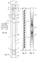
- Figure 1a is a section and in Figure 1b is a shoe-like in a plan view trained holding body 1 shown. It has one in each of its end regions 29 Threaded hole 2 open to accommodate height-adjustable sliding blocks (not here shown), which keeps the stray flux probe at a distance from the test body. Of the Elongated central area is provided with a recess 3, the one has remaining edge region 7.
- a window 22 is provided in the end region, through which a multiple-pole plug element 5 ( Figure 2) can be inserted.
- To attach an adapter board 11 are in Center region of the bottom 28 two threaded blind holes 20 are arranged.
- the circuit board 6 (FIG. 1c, 1d) is fastened via four in the edge region 7 arranged blind holes 4.
- In the edge region of the window 22 are two threaded bores 21 are provided around the multiple-pole plug element 5 to be able to attach.
- Figures 1c, d show a top view and a bottom view of the Printed circuit board 6 according to the invention.
- a plurality of coils 8 are printed on the body to be tested facing side of the circuit board 6.
- the arrangement shown here is only an example, since the angular positions and the geometry of the Coils can be freely selected depending on the test requirements.
- In both End regions of the circuit board 6 are provided with holes 9 around the circuit board 6 attach to the edge area 7 of the holding body 1 by means of countersunk screws 18 can.
- the top of the printed circuit board 6 shown in FIG. 1d shows the individual coils 8 connecting from the respective via 27 to the solder pads 25 Conductor tracks 26.
- FIG. 2 shows a quasi exploded view of the essential components of a Embodiment of the leakage flux probe designed according to the invention.
- a circuit board connector 10 is attached, which over the solder pads 25 is connected to the circuit board 6.
- this Board connector 10 is a complementary on the top of an adapter board 11 arranged to the board connector 10 formed board socket 12. Longitudinal offset from the board socket 12 are tinned holes on the adapter board 11 23 is provided in order to be able to solder the multiple-pole plug element 5.
- the Attachment of the adapter board 11 takes place via holes 16 through which Countersunk screws 17 can be inserted. These are in the bottom 28 of the Holding body 1 arranged threaded blind holes 20 screwed.
- the Attachment of the multiple-pole connector element 5 on the holding body 1 is carried out via Collars 13 arranged holes 14 through the cylinder head screws 19th are insertable. These are in the in the edge region of the window 22 of the Holding body 1 arranged threaded holes 21 screwed.
- an attachable housing 15 is provided to protect the Multiple-pole connector element 5. The The thickness of the circuit board 6 and the depth of the edge region 7 are thus one on the other matched that after mounting the circuit board 6 on the holding body 1 Side with the coils 8 is flush with the edge region 29 of the holding body 1.
- the carrier body 6.1 is in this Embodiment approx. 3 mm thick.
Landscapes
- Chemical & Material Sciences (AREA)
- Analytical Chemistry (AREA)
- Electrochemistry (AREA)
- Physics & Mathematics (AREA)
- Health & Medical Sciences (AREA)
- Life Sciences & Earth Sciences (AREA)
- Chemical Kinetics & Catalysis (AREA)
- Biochemistry (AREA)
- General Health & Medical Sciences (AREA)
- General Physics & Mathematics (AREA)
- Immunology (AREA)
- Pathology (AREA)
- Measuring Leads Or Probes (AREA)
- Investigating Or Analyzing Materials By The Use Of Magnetic Means (AREA)
Abstract
Description
- eine Kostenreduktion um bis zu 90% beim Austausch einer defekten Sonde
- jedes Einzelteil, z. B. Kabel, Adapterplatine, Leiterplatte ist austauschbar und ersetzbar
- eine verringerte, kostengünstigere Lagerhaltung
- Figur 1 a, b, c, d
- Schnitt und Draufsicht eines Haltekörpers sowie Unter- und Oberseite einer erfindungsgemäß ausgebildeten Leiterplatte
- Figur 2
- in einer Seitenansicht einer quasi Explosionsdarstellung die Leiterplatte im Zusammenwirken mit einer erfindungsgemäß ausgebildeten Adapter-Platine, Haltekörper und Stecker
| Nummer | Bezeichnung |
| 1 | Haltekörper |
| 2 | Gewindebohrung |
| 3 | Ausnehmung |
| 4 | Gewindesacklochbohrung |
| 5 | Mehrfachpol-Stecker-Element |
| 6 | Leiterplatte |
| 6.1 | Trägerkörper |
| 6.2 | gedruckte Spulenschicht |
| 6.3 | Schutzschicht |
| 6.4 | gedruckte Leiterschicht |
| 7 | Randbereich |
| 8 | gedruckte Spule |
| 9 | Bohrung |
| 10 | Platinenstecker |
| 11 | Adapter-Platine |
| 12 | Platinen-Buchse |
| 13 | Kragen |
| 14 | Bohrung |
| 15 | Gehäuse für Stecker |
| 16 | Bohrung |
| 17 | Senkschraube |
| 18 | Senkschraube |
| 19 | Zylinderkopfschraube |
| 20 | Gewindesacklochbohrung |
| 21 | Gewindebohrung |
| 22 | Fenster |
| 23 | verzinnte Bohrungen zum Einlöten des Steckers 5 |
| 24 | Einlötkontakte |
| 25 | Lötpads für Leiterplattenstecker 10 |
| 26 | Leiterbahn |
| 27 | Durchkontaktierung |
| 28 | Boden |
| 29 | Endbereich |
Claims (4)
- Streuflußsonde zur zerstörungsfreien Prüfung von langgestreckten, rotationssymmetrischen Körpern, insbesondere Rohre, auf Längs- und / oder Querfehler bestehend aus einer Leiterfolie, die auf der dem zu prüfenden Körper zugewandten Seite mit einer Vielzahl darauf bedruckter Spulen versehen ist, die in einem als Schuh ausgebildeten Haltekörper abdichtend angeordnet ist und die die Spulen verbindenden Leitungen nach außen zu einem Steckeranschluß geführt sind und die dem Körper zugewandte Seite der Leiterfolie zugleich Schutzschicht ist, wobei die Sonde in Achsrichtung des Körpers liegend angeordnet ist und relativ zu dem sich bewegenden Körper rotiert,
dadurch gekennzeichnet,
daß die Leiterfolie als beidseitig bedruckte Leiterplatte (6) ausgebildet ist, wobei auf der die Leitungsbahnen (26) aufweisenden Leiterplattenseite ein Platinenstecker (10) angeordnet ist, der mit einer komplementär dazu ausgebildeten Platinenbuchse (12) zusammenwirkt, die wiederum mit einem am Haltekörper (1) befestigbaren Mehrfachpol-Stecker-Element (5) zusammenwirkt. - Streuflußsonde nach Anspruch 1,
dadurch gekennzeichnet,
daß zwischen der Platinenbuchse (10) und dem Mehrfachpol-Stecker-Element (5) eine Adapter-Platine (11) angeordnet ist, die mit einer komplementär zum Platinenstecker (10) ausgebildeten Platinenbuchse (12) und mit verzinnten Bohrungen (23) zur Befestigung des Mehrfachpol-Stecker-Elementes (5) versehen ist. - Streuflußsonde nach Anspruch 1 und 2,
dadurch gekennzeichnet,
daß der Platinenstecker (10) in der Mitte der Leiterplatte (6) angeordnet ist. - Streuflußsonde nach Anspruch 1 und 2,
dadurch gekennzeichnet,
daß die verzinnten Bohrungen (23) in Längsrichtung versetzt zur Platinenbuchse (12) auf der Adapter-Platine (11) angeordnet sind.
Applications Claiming Priority (2)
| Application Number | Priority Date | Filing Date | Title |
|---|---|---|---|
| DE1998123453 DE19823453C2 (de) | 1998-05-18 | 1998-05-18 | Streuflußsonde zur zerstörungsfreien Prüfung von langgestreckten, rotationssymmetrischen Körpern |
| DE19823453 | 1998-05-18 |
Publications (2)
| Publication Number | Publication Date |
|---|---|
| EP0959349A2 true EP0959349A2 (de) | 1999-11-24 |
| EP0959349A3 EP0959349A3 (de) | 2002-04-17 |
Family
ID=7868947
Family Applications (1)
| Application Number | Title | Priority Date | Filing Date |
|---|---|---|---|
| EP99250130A Withdrawn EP0959349A3 (de) | 1998-05-18 | 1999-04-22 | Streuflusssonde zur zerstörungsfreien Prüfung von langgestreckten, rotationssymmetrischen Körpern |
Country Status (2)
| Country | Link |
|---|---|
| EP (1) | EP0959349A3 (de) |
| DE (1) | DE19823453C2 (de) |
Cited By (2)
| Publication number | Priority date | Publication date | Assignee | Title |
|---|---|---|---|---|
| WO2007012331A3 (de) * | 2005-07-29 | 2007-04-19 | V&M Deutschland Gmbh | Verfahren zur zerstörungsfreien prüfung von rohren auf oberflächenfehler |
| EP2594929A3 (de) * | 2011-11-16 | 2014-03-19 | Vallourec Deutschland GmbH | Streuflusssonde zur zerstörungsfreien Streuflussprüfung von Körpern aus magnetisierbarem Werkstoff |
Families Citing this family (1)
| Publication number | Priority date | Publication date | Assignee | Title |
|---|---|---|---|---|
| DE102011000917B4 (de) | 2011-02-24 | 2017-08-17 | Vallourec Deutschland Gmbh | Streuflusssonde zur zerstörungsfreien Streuflussprüfung von Körpern aus magnetisierbarem Werkstoff |
Citations (2)
| Publication number | Priority date | Publication date | Assignee | Title |
|---|---|---|---|---|
| DE9011478U1 (de) * | 1990-08-07 | 1990-12-20 | Nukem GmbH, 63755 Alzenau | Anordnung zur zerstörungsfreien Werkstoffprüfung |
| DE9011477U1 (de) * | 1990-08-07 | 1990-12-20 | Nukem GmbH, 63755 Alzenau | Anordnung zur zerstörungsfreien Werkstoffprüfung |
Family Cites Families (4)
| Publication number | Priority date | Publication date | Assignee | Title |
|---|---|---|---|---|
| US3504276A (en) * | 1967-04-19 | 1970-03-31 | American Mach & Foundry | Printed circuit coils for use in magnetic flux leakage flow detection |
| DE3337893A1 (de) * | 1983-10-19 | 1985-05-15 | Institut Dr. Friedrich Förster Prüfgerätebau GmbH & Co KG, 7410 Reutlingen | Anordnung zum pruefen eines ferromagnetischen rohres auf fehler |
| US4855677A (en) * | 1988-03-11 | 1989-08-08 | Westinghouse Electric Corp. | Multiple coil eddy current probe and method of flaw detection |
| US5047719A (en) * | 1990-05-25 | 1991-09-10 | The Failure Group, Inc. | Flexible coil assembly for reflectance-mode nondestructive eddy-current examination |
-
1998
- 1998-05-18 DE DE1998123453 patent/DE19823453C2/de not_active Expired - Lifetime
-
1999
- 1999-04-22 EP EP99250130A patent/EP0959349A3/de not_active Withdrawn
Patent Citations (2)
| Publication number | Priority date | Publication date | Assignee | Title |
|---|---|---|---|---|
| DE9011478U1 (de) * | 1990-08-07 | 1990-12-20 | Nukem GmbH, 63755 Alzenau | Anordnung zur zerstörungsfreien Werkstoffprüfung |
| DE9011477U1 (de) * | 1990-08-07 | 1990-12-20 | Nukem GmbH, 63755 Alzenau | Anordnung zur zerstörungsfreien Werkstoffprüfung |
Cited By (3)
| Publication number | Priority date | Publication date | Assignee | Title |
|---|---|---|---|---|
| WO2007012331A3 (de) * | 2005-07-29 | 2007-04-19 | V&M Deutschland Gmbh | Verfahren zur zerstörungsfreien prüfung von rohren auf oberflächenfehler |
| US7783432B2 (en) | 2005-07-29 | 2010-08-24 | V & M Deutschland Gmbh | Method for nondestructive testing of pipes for surface flaws |
| EP2594929A3 (de) * | 2011-11-16 | 2014-03-19 | Vallourec Deutschland GmbH | Streuflusssonde zur zerstörungsfreien Streuflussprüfung von Körpern aus magnetisierbarem Werkstoff |
Also Published As
| Publication number | Publication date |
|---|---|
| DE19823453A1 (de) | 1999-12-09 |
| DE19823453C2 (de) | 2000-04-27 |
| EP0959349A3 (de) | 2002-04-17 |
Similar Documents
| Publication | Publication Date | Title |
|---|---|---|
| DE2659976C2 (de) | Vorrichtung zur Herstellung einer elektrischen Verbindung zwischen einem in einer dynamischen elektrischen Prüfung befindlichen Bauteil und einer Prüfeinrichtung | |
| DE102007020882B4 (de) | Einrichtung zur Überprüfung der Befestigung einer Leiterbahnplatte an einem Träger | |
| DE3716240A1 (de) | Pruefadapter, insbesondere fuer eine integrierte schaltung | |
| DE69923107T2 (de) | Zeitbereichsreflektometrie-Prüfanordnung für eine zweidimensionale Sonde | |
| DE10042224C2 (de) | Modultestsockel für Prüfadapter | |
| DE19907727A1 (de) | Testadapter zur Kontaktierung von bestückten Leiterplatinen | |
| DE19823453C2 (de) | Streuflußsonde zur zerstörungsfreien Prüfung von langgestreckten, rotationssymmetrischen Körpern | |
| EP2096713B1 (de) | Schaltungsanordnung zur Überprüfung einer korrekten Verbindung von Leiterplatten in Gehäusen | |
| EP1982198B1 (de) | Prüfsystem für einen schaltungsträger | |
| DE3518626C2 (de) | ||
| DE4327950A1 (de) | Leitungsstruktur eines Halbleiter-Bauteil | |
| DE3248694A1 (de) | Pruefadapter fuer flache elektrische baugruppen | |
| DE3009236C2 (de) | Anordnung mit Kontaktbuchsen für elektrische Anschlüsse | |
| DE102023003300B3 (de) | Leuchtdiodenband | |
| DE4335879B4 (de) | Anordnung zur Qualitätskontrolle und -überwachung von durchkontaktierten Mehrlagen-Leiterplatten | |
| DE3212403C2 (de) | Adaptereinrichtung zur Herstellung einer lösbaren elektrischen Verbindung zwischen Kontaktelementen einer Verdrahtungsplatte und zugeordneten Kontaktelementen einer Flachbaugruppe | |
| DE9101744U1 (de) | Leiterkarte für die elektrische Schaltung eines Gerätes zur Füllstandmessung von Industrietanks | |
| DE716621C (de) | Stoepselkontaktanordnung fuer elektrische Messeinrichtungen | |
| DE102005011152B4 (de) | Kontaktierungseinrichtung mit kontrollierter Impedanz | |
| DE602005002518T2 (de) | Mit einer mäandrischen Kontaktierungszone versehene elektronische Karte | |
| DE3030101A1 (de) | Anordnung zur pruefung einer flachen integrierten schaltung | |
| DE3133199C2 (de) | Kontaktsokel für elektrische Bauteile | |
| DE102005030550B3 (de) | Vorrichtung zum Prüfen von bestückten oder unbestückten Leiterplatten | |
| WO2013004775A1 (de) | Adapter für eine prüfvorrichtung und prüfvorrichtung zum testen von leiterplatten | |
| DE102004033302A1 (de) | Testvorrichtung für elektronische Schaltungen |
Legal Events
| Date | Code | Title | Description |
|---|---|---|---|
| PUAI | Public reference made under article 153(3) epc to a published international application that has entered the european phase |
Free format text: ORIGINAL CODE: 0009012 |
|
| AK | Designated contracting states |
Kind code of ref document: A2 Designated state(s): AT BE CH CY DE DK ES FI FR GB GR IE IT LI LU MC NL PT SE Kind code of ref document: A2 Designated state(s): DE FR GB IT NL |
|
| AX | Request for extension of the european patent |
Free format text: AL;LT;LV;MK;RO;SI |
|
| RIN1 | Information on inventor provided before grant (corrected) |
Inventor name: NITSCHE, STEFAN Inventor name: ROHDE, HANS-JUERGEN Inventor name: GRAFF, ALFRED Inventor name: ARZT, NORBERT |
|
| PUAL | Search report despatched |
Free format text: ORIGINAL CODE: 0009013 |
|
| AK | Designated contracting states |
Kind code of ref document: A3 Designated state(s): AT BE CH CY DE DK ES FI FR GB GR IE IT LI LU MC NL PT SE |
|
| AX | Request for extension of the european patent |
Free format text: AL;LT;LV;MK;RO;SI |
|
| RIC1 | Information provided on ipc code assigned before grant |
Free format text: 7G 01N 27/82 A, 7G 01N 27/83 B |
|
| 17P | Request for examination filed |
Effective date: 20020703 |
|
| RAP1 | Party data changed (applicant data changed or rights of an application transferred) |
Owner name: V & M DEUTSCHLAND GMBH |
|
| AKX | Designation fees paid |
Free format text: DE FR GB IT NL |
|
| 17Q | First examination report despatched |
Effective date: 20041104 |
|
| GRAP | Despatch of communication of intention to grant a patent |
Free format text: ORIGINAL CODE: EPIDOSNIGR1 |
|
| STAA | Information on the status of an ep patent application or granted ep patent |
Free format text: STATUS: THE APPLICATION IS DEEMED TO BE WITHDRAWN |
|
| 18D | Application deemed to be withdrawn |
Effective date: 20051230 |