EP0959294A2 - Breitstrahlende Indirektleuchte - Google Patents
Breitstrahlende Indirektleuchte Download PDFInfo
- Publication number
- EP0959294A2 EP0959294A2 EP99107617A EP99107617A EP0959294A2 EP 0959294 A2 EP0959294 A2 EP 0959294A2 EP 99107617 A EP99107617 A EP 99107617A EP 99107617 A EP99107617 A EP 99107617A EP 0959294 A2 EP0959294 A2 EP 0959294A2
- Authority
- EP
- European Patent Office
- Prior art keywords
- reflector
- section
- light
- indirect
- plane
- Prior art date
- Legal status (The legal status is an assumption and is not a legal conclusion. Google has not performed a legal analysis and makes no representation as to the accuracy of the status listed.)
- Granted
Links
- 239000000463 material Substances 0.000 claims description 7
- 239000002184 metal Substances 0.000 claims description 3
- 239000005338 frosted glass Substances 0.000 claims description 2
- -1 Mesh Substances 0.000 claims 1
- 239000004744 fabric Substances 0.000 claims 1
- 238000005286 illumination Methods 0.000 description 3
- 230000004313 glare Effects 0.000 description 2
- 239000000725 suspension Substances 0.000 description 2
- 238000011109 contamination Methods 0.000 description 1
- 230000005855 radiation Effects 0.000 description 1
Images

Classifications
-
- F—MECHANICAL ENGINEERING; LIGHTING; HEATING; WEAPONS; BLASTING
- F21—LIGHTING
- F21S—NON-PORTABLE LIGHTING DEVICES; SYSTEMS THEREOF; VEHICLE LIGHTING DEVICES SPECIALLY ADAPTED FOR VEHICLE EXTERIORS
- F21S6/00—Lighting devices intended to be free-standing
- F21S6/005—Lighting devices intended to be free-standing with a lamp housing maintained at a distance from the floor or ground via a support, e.g. standing lamp for ambient lighting
-
- F—MECHANICAL ENGINEERING; LIGHTING; HEATING; WEAPONS; BLASTING
- F21—LIGHTING
- F21V—FUNCTIONAL FEATURES OR DETAILS OF LIGHTING DEVICES OR SYSTEMS THEREOF; STRUCTURAL COMBINATIONS OF LIGHTING DEVICES WITH OTHER ARTICLES, NOT OTHERWISE PROVIDED FOR
- F21V7/00—Reflectors for light sources
- F21V7/0008—Reflectors for light sources providing for indirect lighting
-
- F—MECHANICAL ENGINEERING; LIGHTING; HEATING; WEAPONS; BLASTING
- F21—LIGHTING
- F21S—NON-PORTABLE LIGHTING DEVICES; SYSTEMS THEREOF; VEHICLE LIGHTING DEVICES SPECIALLY ADAPTED FOR VEHICLE EXTERIORS
- F21S6/00—Lighting devices intended to be free-standing
Definitions
- the invention relates to a wide-beam indirect light according to the preamble of claim 1.
- the invention is therefore intended to be a lamp of the beginning mentioned type can be improved so that even with fluorescent tubes with a smaller diameter a good and even illumination of the room while avoiding excessive luminance achieved on the ceiling directly above the lamp can be.
- the arrangement of perforated sheet metal parts in the housing together with other reflectors in the middle, side and bottom of the interior of the Luminaire housing can optionally be used for an even smoother Light distribution and avoidance of shadows and especially for uniform lightening of the housing worry down.
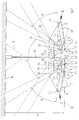
- the relatively flat lamp housing 14 Since the distance A from the ceiling 10 to the lower edge 12 of the 1 should be as small as possible, is the relatively flat lamp housing 14 by means of a short lamp shaft 16 and an approximately conical one Ceiling rosette 18 attached at a short distance from the ceiling 10.
- the lamp housing 14 is slightly convex downwards curved and is made of translucent material that however e.g. in the form of perforated sheet, mesh, mesh, Frosted glass or other perforated material optionally let more or less light down can. Ends at the side edges of the lamp housing 14 the same in each case in sections 22 bent over the lamp housing 14 is open at the top.
- the lamp housing 14 is symmetrical to one in the direction the longitudinal extent of the lamp housing 14 extending vertical center plane 26 formed. At equal intervals from the central plane 26 and at the same height above the Housing 14, i.e. approximately at the level of the bent sections 22 of the lamp housing 14, one is parallel to the central plane 26 extending tube 28 arranged.
- each tube 28 is a perforated plate High-gloss reflector arranged, generally designated 30 is.
- a first approximately vertical section 32 lies on the the central plane 26 side of the associated fluorescent tube 28 and protrudes slightly above it. In a little Distance from the top of the tube 28 closes to the first section 32 a second approximately horizontal Section 34 of the reflector 30, the length of which approximately Diameter of the fluorescent tube 28 corresponds.
- the second section 34 then goes into a third, from the middle level 26 away upward sloping longer section 36 over the slightly convex upwards and slightly concave downwards is. In the illustrated embodiment, it has one average slope of about 45 °.
- the length of the third section 36 is a multiple of the first section 32 and the second section 34.
- Center reflector 38 provided on both sides the middle plane 26 an upper, up to the middle plane 26 inclined flat reflector surface 40 and a lower, essentially sloping down towards the median plane has flat reflector surface 42.
- the center reflector 38 also points downward from the central plane 26 inclined, each arranged below one of the fluorescent tubes 28 Sub-reflector 44, which is integral with it or is otherwise rigidly connected. Between each lower flat reflector surface 42 and the upper edge 46 of the Sub-reflector 44 is parallel to the central plane 26 the length of the entire opening 48 provided, at most by thin, not shown Retaining bars or the like can be interrupted.
- the entire center reflector 38 including the sub-reflector 44 is preferably made of closed high-gloss material.
- the lower edge 50 of the first vertical section 32 each Reflector 30 is preferably on the top of the associated Sub-reflector 44 on.
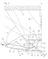
- Section D of the lamp housing 14 is spaced apart a side reflector 52 is attached approximately parallel to each. It runs approximately from the bent portions 22 of the Housing 14 up to its inner edge 54 each in a small amount Distance below the associated fluorescent tube 28 and above of the associated sub-reflector 44 and is except for the outer Edge areas essentially flat. It preferably exists also made of closed high-gloss material and is for Median plane slightly inclined downwards, so that between the side reflector 52 and the third section 36 of the associated reflector 30 an opening upwards from Reflectors unobstructed beam angle B for the light of the associated fluorescent tube 28 is formed.
- the beam angle range B points diagonally upwards, causing glare safely avoided in the direction of arrow G from obliquely below a good and even illumination of the room is reached laterally and upwards.
- the third curved section 36 of the perforated plate reflector 30 is decisive for the size of the beam angle B.
- the direct beam from the tube 28 down towards the Housing 14 is through the side reflector 52 and the sub-reflector 44 prevented.
- the side reflector supports 52 each have the wide-beam characteristic of Luminaire essentially determined by the angle B. becomes.
- the described shape of the three sections of the two perforated sheet reflectors 30 serves for a certain, but not complete Shading of the fluorescent tubes 28 towards the ceiling 10 above the reflectors 30. It results from the perforated plate of these reflectors 30 determined by the angle C. Beam area directly up against the ceiling 10.
- the angle of incidence is partial so flat that there is no direct light, for example, through holes in a perforated sheet material of the housing 14 would penetrate to the outside. Thereby is a largely uniform lightening of the case 14 reached. To optimize this, it could be advantageous a transparent film is placed on the inside of the housing 14 become.
Landscapes
- Engineering & Computer Science (AREA)
- General Engineering & Computer Science (AREA)
- Non-Portable Lighting Devices Or Systems Thereof (AREA)
- Laser Surgery Devices (AREA)
- Vessels And Coating Films For Discharge Lamps (AREA)
- Securing Globes, Refractors, Reflectors Or The Like (AREA)
- Luminescent Compositions (AREA)
Abstract
Description
- Figur 1
- einen schematischen Schnitt senkrecht zur Längserstreckung der an einer Raumdecke kurz abgehängten Indirektleuchte gemäß der Erfindung,
- Figur 2
- eine vergrößerte Darstellung der linken Hälfte der Fig. 1,
- Figur 3
- eine verkleinerte Darstellung der Leuchte gemäß Fig. 1, und
- Figur 4
- die auf einem hohen Ständer nahe der Raumdecke angebrachte Leuchte gemäß Fig.1 ohne die der Aufhängung dienenden Teile.
Claims (9)
- Breitstrahlende Indirektleuchte mit einem langgestreckten, symmetrisch zu einer vertikalen Mittelebene (26) verlaufenden, für den Lichtaustritt nach unten durchlässigen und nach oben offenen Leuchtengehäuse, zwei in demselben in gleichem Abstand zu beiden Seiten der Mittelebene angeordneten Leuchtröhren und mindestens je einem Reflektor im Leuchtengehäuse nahe jeder Leuchtröhre, der die Abstrahlung derselben nach oben wenigstens teilweise ablenkt, dadurch gekennzeichnet, daß jeder Reflektor (30) aus Lochblech besteht und im vertikalen Querschnitt einen ersten etwa vertikalen Abschnitt (32) auf der zur Mittelebene (26) hin weisenden Seite der zugehörigen Leuchtröhre (28), einen zweiten etwa horizontalen Abschnitt (34) an der Oberseite der zugehörigen Leuchtröhre (28) und einen jeweils an den zweiten Abschnitt (34) anschließenden dritten Abschnitt (36) umfaßt, wobei der dritte Abschnitt (36) schräg nach oben von der Mittelebene (26) weg geneigt verläuft.
- Indirektleuchte nach Anspruch 1, dadurch gekennzeichnet, daß der dritte Abschnitt (36) jeweils zur Mittelebene (26) hin leicht konkav gewölbt ist.
- Indirektleuchte nach Anspruch 1 oder 2, bei welcher im Bereich zwischen den beiden Reflektoren und den beiden Leuchtröhren ein Mittelreflektor symmetrisch zur Mittelebene angeordnet ist, der zwei obere, nach oben zur Mittelebene hin geneigte Ebene oder nur leicht gekrümmte Reflektorflächen und zwei untere, nach unten zur Mittelebene hingeneigte Ebene oder nur leicht gekrümmte Reflektorflächen aufweist, dadurch gekennzeichnet, daß der Mittelreflektor (38) je einen nach unten von der Mittelebene (26) weggeneigten, jeweils unterhalb einer der Leuchtröhren (28) angeordneten Unterreflektor (44) aufweist, wobei jeweils zwischen der unteren etwa ebenen Reflektorfläche (42) und dem oberen Rand (46) des Unterreflektors (44) wenigstens ein Durchbruch (48) vorgesehen ist.
- Indirektleuchte nach Anspruch 1 oder 2, dadurch gekennzeichnet, daß das Leuchtengehäuse (14) wenigstens teilweise aus teildurchlässigem Material, wie Lochblech, Gittergewebe, Gittergeflecht, Milchglas oder perforiertem Material besteht.
- Indirektleuchte nach Anspruch 3 oder 4, dadurch gekennzeichnet, daß der untere Rand (50) des ersten etwa vertikalen Abschnitts (32) jedes Reflektors (30) vorzugsweise an der Oberseite des zugehörigen Unterreflektors (44) anliegt.
- Indirektleuchte nach einem der vorangehenden Ansprüche, dadurch gekennzeichnet, daß oberhalb der von der Mittelebene (26) abgelegenen seitlichen Abschnitte (D) des Leuchtengehäuses (14) im Abstand etwa parallel zu diesen je ein Seitenreflektor (52) angeordnet ist.
- Indirektleuchte nach Anspruch 6, dadurch gekennzeichnet, daß jeder Seitenreflektor (52) zur Mittelebene (26) hin nach unten leicht derart geneigt ist, daß zwischen dem Seitenreflektor (52) und dem dritten Abschnitt (36) des zugehörigen Reflektors (30) ein sich nach oben öffnender, von Reflektoren unbehinderter Abstrahlwinkel (B) für das Licht der zugehörigen Leuchtröhre (28) gebildet wird.
- Indirektleuchte nach Anspruch 6 oder 7, dadurch gekennzeichnet, daß der zur Mittelebene (26) hin weisende Rand (54) jedes Seitenreflektors (52) unterhalb der zugehörigen Leuchtröhre (28) in geringem Abstand von der Oberseite des zugehörigen Unterreflektors (44) verläuft.
- Indirektleuchte nach einem der Ansprüche 3 bis 8, dadurch gekennzeichnet, daß über dem Mittelreflektor (38) und den Leuchtröhren (28) eine lichtdurchlässige horizontale Abdeckplatte (56) im Leuchtengehäuse angeordnet ist.
Applications Claiming Priority (2)
| Application Number | Priority Date | Filing Date | Title |
|---|---|---|---|
| DE19822305 | 1998-05-18 | ||
| DE19822305A DE19822305C1 (de) | 1998-05-18 | 1998-05-18 | Breitstrahlende Indirektleuchte |
Publications (3)
| Publication Number | Publication Date |
|---|---|
| EP0959294A2 true EP0959294A2 (de) | 1999-11-24 |
| EP0959294A3 EP0959294A3 (de) | 2001-04-11 |
| EP0959294B1 EP0959294B1 (de) | 2006-08-30 |
Family
ID=7868198
Family Applications (1)
| Application Number | Title | Priority Date | Filing Date |
|---|---|---|---|
| EP99107617A Expired - Lifetime EP0959294B1 (de) | 1998-05-18 | 1999-04-16 | Breitstrahlende Indirektleuchte |
Country Status (7)
| Country | Link |
|---|---|
| US (1) | US6042246A (de) |
| EP (1) | EP0959294B1 (de) |
| CN (1) | CN1109217C (de) |
| AT (1) | ATE338246T1 (de) |
| DE (2) | DE19822305C1 (de) |
| DK (1) | DK0959294T3 (de) |
| SG (1) | SG77233A1 (de) |
Families Citing this family (10)
| Publication number | Priority date | Publication date | Assignee | Title |
|---|---|---|---|---|
| US6837592B1 (en) | 2000-04-06 | 2005-01-04 | Genlyte Thomas Group, Llc | Indirect luminaire optical system |
| US6505953B1 (en) | 2000-04-06 | 2003-01-14 | Genlyte Thomas Group Llc | Luminaire optical system |
| US20050201103A1 (en) * | 2004-03-12 | 2005-09-15 | Honeywell International Inc. | Luminaires with batwing light distribution |
| US7621133B2 (en) * | 2005-11-18 | 2009-11-24 | General Electric Company | Methods and apparatus for starting up combined cycle power systems |
| US8002446B1 (en) | 2008-06-09 | 2011-08-23 | Koninklijke Philips Electronics N.V. | Virtual direct and indirect suspended lighting fixture |
| US8342722B1 (en) * | 2010-02-12 | 2013-01-01 | Opdahl Nicholas C | Light system |
| US9140420B2 (en) * | 2011-06-14 | 2015-09-22 | Osram Sylvania Inc. | Edge-lit light panel having a downlight within a lined indentation in the panel |
| US10739513B2 (en) * | 2018-08-31 | 2020-08-11 | RAB Lighting Inc. | Apparatuses and methods for efficiently directing light toward and away from a mounting surface |
| CN112147115B (zh) * | 2020-08-31 | 2023-10-27 | 中国科学院苏州生物医学工程技术研究所 | 一种荧光采集装置及核酸检测装置 |
| CN114370615A (zh) * | 2021-12-30 | 2022-04-19 | 苏州欧普照明有限公司 | 控光模组、控光模组的设计方法及灯具 |
Citations (1)
| Publication number | Priority date | Publication date | Assignee | Title |
|---|---|---|---|---|
| DE19537685C1 (de) | 1995-10-10 | 1997-03-13 | Waldmann Gmbh & Co Herbert | Breitstrahlende Indirektleuchte |
Family Cites Families (5)
| Publication number | Priority date | Publication date | Assignee | Title |
|---|---|---|---|---|
| US2545058A (en) * | 1948-07-26 | 1951-03-13 | John S Walsh | Lighting fixture for use with elogated tubular lamps |
| US3803401A (en) * | 1970-10-21 | 1974-04-09 | H Drews | Reflectors for strip type fluorescent lighting |
| EP0217323A3 (de) * | 1985-10-02 | 1989-03-08 | THORN LICHT GmbH | Leuchte und Beleuchtungsverfahren |
| US5075827A (en) * | 1990-10-31 | 1991-12-24 | Smith David H | Indirect light fixture amplification reflector system |
| ATE123335T1 (de) * | 1991-10-24 | 1995-06-15 | Zumtobel Licht | Reflektor für eine leuchte. |
-
1998
- 1998-05-18 DE DE19822305A patent/DE19822305C1/de not_active Expired - Fee Related
-
1999
- 1999-04-16 AT AT99107617T patent/ATE338246T1/de active
- 1999-04-16 EP EP99107617A patent/EP0959294B1/de not_active Expired - Lifetime
- 1999-04-16 DK DK99107617T patent/DK0959294T3/da active
- 1999-04-16 DE DE59913806T patent/DE59913806D1/de not_active Expired - Lifetime
- 1999-05-07 SG SG1999002142A patent/SG77233A1/en unknown
- 1999-05-12 CN CN99106471A patent/CN1109217C/zh not_active Expired - Fee Related
- 1999-05-18 US US09/313,614 patent/US6042246A/en not_active Expired - Lifetime
Patent Citations (1)
| Publication number | Priority date | Publication date | Assignee | Title |
|---|---|---|---|---|
| DE19537685C1 (de) | 1995-10-10 | 1997-03-13 | Waldmann Gmbh & Co Herbert | Breitstrahlende Indirektleuchte |
Also Published As
| Publication number | Publication date |
|---|---|
| CN1236077A (zh) | 1999-11-24 |
| ATE338246T1 (de) | 2006-09-15 |
| EP0959294B1 (de) | 2006-08-30 |
| DE59913806D1 (de) | 2006-10-12 |
| DK0959294T3 (da) | 2007-01-08 |
| US6042246A (en) | 2000-03-28 |
| DE19822305C1 (de) | 1999-12-02 |
| CN1109217C (zh) | 2003-05-21 |
| EP0959294A3 (de) | 2001-04-11 |
| SG77233A1 (en) | 2000-12-19 |
Similar Documents
| Publication | Publication Date | Title |
|---|---|---|
| EP1043542B2 (de) | Beleuchtungsanordnung zur Anbringung an der Decke oder einer Wand eines Raumes | |
| DE69608044T2 (de) | Leuchte | |
| DE7118967U (de) | Deckenbeleuchtungskoerper und darin verwendbare lichtdurchlaessige huelle | |
| DE19822305C1 (de) | Breitstrahlende Indirektleuchte | |
| DE29909282U1 (de) | Leuchte | |
| DE19537685C1 (de) | Breitstrahlende Indirektleuchte | |
| EP1338845B1 (de) | Leuchte | |
| DE2707037C2 (de) | Abschirmung für die direkte Aufhängung an einer langgestreckten Lichtquelle | |
| EP1635379B1 (de) | Reflektorlampe | |
| EP2116761A1 (de) | Fassadenbeleuchtungsvorrichtung sowie Fassadenstrahler hierfür | |
| DE69012812T2 (de) | Verbesserungen an befestigungen für beleuchtungsröhren. | |
| EP0372272B1 (de) | Spiegelrasterleuchte | |
| DE3030080C2 (de) | Langgestreckte Arbeitsplatzleuchte | |
| EP2112426A2 (de) | Leuchte mit einer langgestreckten Lichtquelle und mit einem ebenfalls langgestrecktem Lichtleitelement | |
| EP0638764B1 (de) | Vorwiegend direkt strahlende Innenleuchte | |
| DE4215968A1 (de) | Lichtlenkende Struktur zum Beleuchten eines Raumes mit Tageslicht | |
| EP1232363B2 (de) | Entblendungstransparent für leuchtkörper | |
| DE1275493B (de) | Strassenleuchte | |
| EP1496308A2 (de) | Innenraumleuchte mit einem Entblendungskörper | |
| EP0008006B1 (de) | Innenleuchte | |
| DE4125545A1 (de) | Indirekte spiegelleuchte | |
| EP0516976A2 (de) | Pollerleuchte | |
| EP1447618A1 (de) | Decken- und Stehleuchte | |
| DE10213536B4 (de) | Sekundärbeleuchtungssystem sowie Leuchte mit einem solchen Sekundärbeleuchtungssystem | |
| DE10354462B4 (de) | Leuchte mit asymmetrischer Lichtabstrahlung |
Legal Events
| Date | Code | Title | Description |
|---|---|---|---|
| PUAI | Public reference made under article 153(3) epc to a published international application that has entered the european phase |
Free format text: ORIGINAL CODE: 0009012 |
|
| AK | Designated contracting states |
Kind code of ref document: A2 Designated state(s): AT BE CH DE DK FR GB IT LI LU NL SE |
|
| AX | Request for extension of the european patent |
Free format text: AL;LT;LV;MK;RO;SI |
|
| PUAL | Search report despatched |
Free format text: ORIGINAL CODE: 0009013 |
|
| AK | Designated contracting states |
Kind code of ref document: A3 Designated state(s): AT BE CH CY DE DK ES FI FR GB GR IE IT LI LU MC NL PT SE |
|
| AX | Request for extension of the european patent |
Free format text: AL;LT;LV;MK;RO;SI |
|
| 17P | Request for examination filed |
Effective date: 20010505 |
|
| AKX | Designation fees paid |
Free format text: AT BE CH DE DK FR GB IT LI LU NL SE |
|
| GRAP | Despatch of communication of intention to grant a patent |
Free format text: ORIGINAL CODE: EPIDOSNIGR1 |
|
| GRAS | Grant fee paid |
Free format text: ORIGINAL CODE: EPIDOSNIGR3 |
|
| GRAA | (expected) grant |
Free format text: ORIGINAL CODE: 0009210 |
|
| AK | Designated contracting states |
Kind code of ref document: B1 Designated state(s): AT BE CH DE DK FR GB IT LI LU NL SE |
|
| PG25 | Lapsed in a contracting state [announced via postgrant information from national office to epo] |
Ref country code: IT Free format text: LAPSE BECAUSE OF FAILURE TO SUBMIT A TRANSLATION OF THE DESCRIPTION OR TO PAY THE FEE WITHIN THE PRESCRIBED TIME-LIMIT;WARNING: LAPSES OF ITALIAN PATENTS WITH EFFECTIVE DATE BEFORE 2007 MAY HAVE OCCURRED AT ANY TIME BEFORE 2007. THE CORRECT EFFECTIVE DATE MAY BE DIFFERENT FROM THE ONE RECORDED. Effective date: 20060830 |
|
| REG | Reference to a national code |
Ref country code: GB Ref legal event code: FG4D Free format text: NOT ENGLISH |
|
| REG | Reference to a national code |
Ref country code: CH Ref legal event code: EP |
|
| REF | Corresponds to: |
Ref document number: 59913806 Country of ref document: DE Date of ref document: 20061012 Kind code of ref document: P |
|
| GBT | Gb: translation of ep patent filed (gb section 77(6)(a)/1977) |
Effective date: 20060924 |
|
| REG | Reference to a national code |
Ref country code: CH Ref legal event code: NV Representative=s name: R. A. EGLI & CO. PATENTANWAELTE |
|
| REG | Reference to a national code |
Ref country code: SE Ref legal event code: TRGR |
|
| REG | Reference to a national code |
Ref country code: DK Ref legal event code: T3 |
|
| ET | Fr: translation filed | ||
| PLBE | No opposition filed within time limit |
Free format text: ORIGINAL CODE: 0009261 |
|
| STAA | Information on the status of an ep patent application or granted ep patent |
Free format text: STATUS: NO OPPOSITION FILED WITHIN TIME LIMIT |
|
| 26N | No opposition filed |
Effective date: 20070531 |
|
| PGFP | Annual fee paid to national office [announced via postgrant information from national office to epo] |
Ref country code: LU Payment date: 20110420 Year of fee payment: 13 |
|
| PGFP | Annual fee paid to national office [announced via postgrant information from national office to epo] |
Ref country code: GB Payment date: 20110316 Year of fee payment: 13 Ref country code: SE Payment date: 20110419 Year of fee payment: 13 |
|
| PGFP | Annual fee paid to national office [announced via postgrant information from national office to epo] |
Ref country code: NL Payment date: 20110420 Year of fee payment: 13 Ref country code: DK Payment date: 20110426 Year of fee payment: 13 Ref country code: BE Payment date: 20110419 Year of fee payment: 13 |
|
| BERE | Be: lapsed |
Owner name: HERBERT *WALDMANN G.M.B.H. & CO. Effective date: 20120430 |
|
| REG | Reference to a national code |
Ref country code: NL Ref legal event code: V1 Effective date: 20121101 |
|
| REG | Reference to a national code |
Ref country code: DK Ref legal event code: EBP |
|
| REG | Reference to a national code |
Ref country code: SE Ref legal event code: EUG |
|
| GBPC | Gb: european patent ceased through non-payment of renewal fee |
Effective date: 20120416 |
|
| PG25 | Lapsed in a contracting state [announced via postgrant information from national office to epo] |
Ref country code: GB Free format text: LAPSE BECAUSE OF NON-PAYMENT OF DUE FEES Effective date: 20120416 Ref country code: BE Free format text: LAPSE BECAUSE OF NON-PAYMENT OF DUE FEES Effective date: 20120430 |
|
| PG25 | Lapsed in a contracting state [announced via postgrant information from national office to epo] |
Ref country code: SE Free format text: LAPSE BECAUSE OF NON-PAYMENT OF DUE FEES Effective date: 20120417 |
|
| PG25 | Lapsed in a contracting state [announced via postgrant information from national office to epo] |
Ref country code: NL Free format text: LAPSE BECAUSE OF NON-PAYMENT OF DUE FEES Effective date: 20121101 |
|
| PG25 | Lapsed in a contracting state [announced via postgrant information from national office to epo] |
Ref country code: DK Free format text: LAPSE BECAUSE OF NON-PAYMENT OF DUE FEES Effective date: 20120430 |
|
| PG25 | Lapsed in a contracting state [announced via postgrant information from national office to epo] |
Ref country code: LU Free format text: LAPSE BECAUSE OF NON-PAYMENT OF DUE FEES Effective date: 20120416 |
|
| REG | Reference to a national code |
Ref country code: FR Ref legal event code: PLFP Year of fee payment: 18 |
|
| REG | Reference to a national code |
Ref country code: FR Ref legal event code: PLFP Year of fee payment: 19 |
|
| REG | Reference to a national code |
Ref country code: FR Ref legal event code: PLFP Year of fee payment: 20 |
|
| PGFP | Annual fee paid to national office [announced via postgrant information from national office to epo] |
Ref country code: CH Payment date: 20180424 Year of fee payment: 20 Ref country code: DE Payment date: 20180525 Year of fee payment: 20 |
|
| PGFP | Annual fee paid to national office [announced via postgrant information from national office to epo] |
Ref country code: AT Payment date: 20180418 Year of fee payment: 20 Ref country code: IT Payment date: 20180420 Year of fee payment: 20 Ref country code: FR Payment date: 20180424 Year of fee payment: 20 |
|
| REG | Reference to a national code |
Ref country code: DE Ref legal event code: R071 Ref document number: 59913806 Country of ref document: DE |
|
| REG | Reference to a national code |
Ref country code: CH Ref legal event code: PL |
|
| REG | Reference to a national code |
Ref country code: AT Ref legal event code: MK07 Ref document number: 338246 Country of ref document: AT Kind code of ref document: T Effective date: 20190416 |