EP0959216A2 - Assembly for hydraulically operating a tailgate - Google Patents
Assembly for hydraulically operating a tailgate Download PDFInfo
- Publication number
- EP0959216A2 EP0959216A2 EP99890103A EP99890103A EP0959216A2 EP 0959216 A2 EP0959216 A2 EP 0959216A2 EP 99890103 A EP99890103 A EP 99890103A EP 99890103 A EP99890103 A EP 99890103A EP 0959216 A2 EP0959216 A2 EP 0959216A2
- Authority
- EP
- European Patent Office
- Prior art keywords
- valve
- cover flap
- working
- tank
- hydraulic
- Prior art date
- Legal status (The legal status is an assumption and is not a legal conclusion. Google has not performed a legal analysis and makes no representation as to the accuracy of the status listed.)
- Granted
Links
Images
Classifications
-
- F—MECHANICAL ENGINEERING; LIGHTING; HEATING; WEAPONS; BLASTING
- F15—FLUID-PRESSURE ACTUATORS; HYDRAULICS OR PNEUMATICS IN GENERAL
- F15B—SYSTEMS ACTING BY MEANS OF FLUIDS IN GENERAL; FLUID-PRESSURE ACTUATORS, e.g. SERVOMOTORS; DETAILS OF FLUID-PRESSURE SYSTEMS, NOT OTHERWISE PROVIDED FOR
- F15B7/00—Systems in which the movement produced is definitely related to the output of a volumetric pump; Telemotors
- F15B7/005—With rotary or crank input
- F15B7/006—Rotary pump input
-
- F—MECHANICAL ENGINEERING; LIGHTING; HEATING; WEAPONS; BLASTING
- F15—FLUID-PRESSURE ACTUATORS; HYDRAULICS OR PNEUMATICS IN GENERAL
- F15B—SYSTEMS ACTING BY MEANS OF FLUIDS IN GENERAL; FLUID-PRESSURE ACTUATORS, e.g. SERVOMOTORS; DETAILS OF FLUID-PRESSURE SYSTEMS, NOT OTHERWISE PROVIDED FOR
- F15B11/00—Servomotor systems without provision for follow-up action; Circuits therefor
- F15B11/003—Systems with load-holding valves
-
- F—MECHANICAL ENGINEERING; LIGHTING; HEATING; WEAPONS; BLASTING
- F15—FLUID-PRESSURE ACTUATORS; HYDRAULICS OR PNEUMATICS IN GENERAL
- F15B—SYSTEMS ACTING BY MEANS OF FLUIDS IN GENERAL; FLUID-PRESSURE ACTUATORS, e.g. SERVOMOTORS; DETAILS OF FLUID-PRESSURE SYSTEMS, NOT OTHERWISE PROVIDED FOR
- F15B13/00—Details of servomotor systems ; Valves for servomotor systems
- F15B13/10—Special arrangements for operating the actuated device with or without using fluid pressure, e.g. for emergency use
-
- E—FIXED CONSTRUCTIONS
- E05—LOCKS; KEYS; WINDOW OR DOOR FITTINGS; SAFES
- E05Y—INDEXING SCHEME RELATING TO HINGES OR OTHER SUSPENSION DEVICES FOR DOORS, WINDOWS OR WINGS AND DEVICES FOR MOVING WINGS INTO OPEN OR CLOSED POSITION, CHECKS FOR WINGS AND WING FITTINGS NOT OTHERWISE PROVIDED FOR, CONCERNED WITH THE FUNCTIONING OF THE WING
- E05Y2900/00—Application of doors, windows, wings or fittings thereof
- E05Y2900/50—Application of doors, windows, wings or fittings thereof for vehicles
- E05Y2900/53—Application of doors, windows, wings or fittings thereof for vehicles characterised by the type of wing
- E05Y2900/546—Tailgates
-
- F—MECHANICAL ENGINEERING; LIGHTING; HEATING; WEAPONS; BLASTING
- F15—FLUID-PRESSURE ACTUATORS; HYDRAULICS OR PNEUMATICS IN GENERAL
- F15B—SYSTEMS ACTING BY MEANS OF FLUIDS IN GENERAL; FLUID-PRESSURE ACTUATORS, e.g. SERVOMOTORS; DETAILS OF FLUID-PRESSURE SYSTEMS, NOT OTHERWISE PROVIDED FOR
- F15B2211/00—Circuits for servomotor systems
- F15B2211/20—Fluid pressure source, e.g. accumulator or variable axial piston pump
- F15B2211/205—Systems with pumps
- F15B2211/20507—Type of prime mover
- F15B2211/20515—Electric motor
-
- F—MECHANICAL ENGINEERING; LIGHTING; HEATING; WEAPONS; BLASTING
- F15—FLUID-PRESSURE ACTUATORS; HYDRAULICS OR PNEUMATICS IN GENERAL
- F15B—SYSTEMS ACTING BY MEANS OF FLUIDS IN GENERAL; FLUID-PRESSURE ACTUATORS, e.g. SERVOMOTORS; DETAILS OF FLUID-PRESSURE SYSTEMS, NOT OTHERWISE PROVIDED FOR
- F15B2211/00—Circuits for servomotor systems
- F15B2211/20—Fluid pressure source, e.g. accumulator or variable axial piston pump
- F15B2211/205—Systems with pumps
- F15B2211/2053—Type of pump
- F15B2211/20561—Type of pump reversible
-
- F—MECHANICAL ENGINEERING; LIGHTING; HEATING; WEAPONS; BLASTING
- F15—FLUID-PRESSURE ACTUATORS; HYDRAULICS OR PNEUMATICS IN GENERAL
- F15B—SYSTEMS ACTING BY MEANS OF FLUIDS IN GENERAL; FLUID-PRESSURE ACTUATORS, e.g. SERVOMOTORS; DETAILS OF FLUID-PRESSURE SYSTEMS, NOT OTHERWISE PROVIDED FOR
- F15B2211/00—Circuits for servomotor systems
- F15B2211/20—Fluid pressure source, e.g. accumulator or variable axial piston pump
- F15B2211/27—Directional control by means of the pressure source
-
- F—MECHANICAL ENGINEERING; LIGHTING; HEATING; WEAPONS; BLASTING
- F15—FLUID-PRESSURE ACTUATORS; HYDRAULICS OR PNEUMATICS IN GENERAL
- F15B—SYSTEMS ACTING BY MEANS OF FLUIDS IN GENERAL; FLUID-PRESSURE ACTUATORS, e.g. SERVOMOTORS; DETAILS OF FLUID-PRESSURE SYSTEMS, NOT OTHERWISE PROVIDED FOR
- F15B2211/00—Circuits for servomotor systems
- F15B2211/30—Directional control
- F15B2211/305—Directional control characterised by the type of valves
- F15B2211/30505—Non-return valves, i.e. check valves
- F15B2211/3051—Cross-check valves
-
- F—MECHANICAL ENGINEERING; LIGHTING; HEATING; WEAPONS; BLASTING
- F15—FLUID-PRESSURE ACTUATORS; HYDRAULICS OR PNEUMATICS IN GENERAL
- F15B—SYSTEMS ACTING BY MEANS OF FLUIDS IN GENERAL; FLUID-PRESSURE ACTUATORS, e.g. SERVOMOTORS; DETAILS OF FLUID-PRESSURE SYSTEMS, NOT OTHERWISE PROVIDED FOR
- F15B2211/00—Circuits for servomotor systems
- F15B2211/30—Directional control
- F15B2211/315—Directional control characterised by the connections of the valve or valves in the circuit
- F15B2211/31523—Directional control characterised by the connections of the valve or valves in the circuit being connected to a pressure source and an output member
- F15B2211/31529—Directional control characterised by the connections of the valve or valves in the circuit being connected to a pressure source and an output member having a single pressure source and a single output member
-
- F—MECHANICAL ENGINEERING; LIGHTING; HEATING; WEAPONS; BLASTING
- F15—FLUID-PRESSURE ACTUATORS; HYDRAULICS OR PNEUMATICS IN GENERAL
- F15B—SYSTEMS ACTING BY MEANS OF FLUIDS IN GENERAL; FLUID-PRESSURE ACTUATORS, e.g. SERVOMOTORS; DETAILS OF FLUID-PRESSURE SYSTEMS, NOT OTHERWISE PROVIDED FOR
- F15B2211/00—Circuits for servomotor systems
- F15B2211/30—Directional control
- F15B2211/32—Directional control characterised by the type of actuation
- F15B2211/329—Directional control characterised by the type of actuation actuated by fluid pressure
-
- F—MECHANICAL ENGINEERING; LIGHTING; HEATING; WEAPONS; BLASTING
- F15—FLUID-PRESSURE ACTUATORS; HYDRAULICS OR PNEUMATICS IN GENERAL
- F15B—SYSTEMS ACTING BY MEANS OF FLUIDS IN GENERAL; FLUID-PRESSURE ACTUATORS, e.g. SERVOMOTORS; DETAILS OF FLUID-PRESSURE SYSTEMS, NOT OTHERWISE PROVIDED FOR
- F15B2211/00—Circuits for servomotor systems
- F15B2211/40—Flow control
- F15B2211/405—Flow control characterised by the type of flow control means or valve
- F15B2211/40515—Flow control characterised by the type of flow control means or valve with variable throttles or orifices
-
- F—MECHANICAL ENGINEERING; LIGHTING; HEATING; WEAPONS; BLASTING
- F15—FLUID-PRESSURE ACTUATORS; HYDRAULICS OR PNEUMATICS IN GENERAL
- F15B—SYSTEMS ACTING BY MEANS OF FLUIDS IN GENERAL; FLUID-PRESSURE ACTUATORS, e.g. SERVOMOTORS; DETAILS OF FLUID-PRESSURE SYSTEMS, NOT OTHERWISE PROVIDED FOR
- F15B2211/00—Circuits for servomotor systems
- F15B2211/40—Flow control
- F15B2211/415—Flow control characterised by the connections of the flow control means in the circuit
- F15B2211/41527—Flow control characterised by the connections of the flow control means in the circuit being connected to an output member and a directional control valve
-
- F—MECHANICAL ENGINEERING; LIGHTING; HEATING; WEAPONS; BLASTING
- F15—FLUID-PRESSURE ACTUATORS; HYDRAULICS OR PNEUMATICS IN GENERAL
- F15B—SYSTEMS ACTING BY MEANS OF FLUIDS IN GENERAL; FLUID-PRESSURE ACTUATORS, e.g. SERVOMOTORS; DETAILS OF FLUID-PRESSURE SYSTEMS, NOT OTHERWISE PROVIDED FOR
- F15B2211/00—Circuits for servomotor systems
- F15B2211/40—Flow control
- F15B2211/45—Control of bleed-off flow, e.g. control of bypass flow to the return line
-
- F—MECHANICAL ENGINEERING; LIGHTING; HEATING; WEAPONS; BLASTING
- F15—FLUID-PRESSURE ACTUATORS; HYDRAULICS OR PNEUMATICS IN GENERAL
- F15B—SYSTEMS ACTING BY MEANS OF FLUIDS IN GENERAL; FLUID-PRESSURE ACTUATORS, e.g. SERVOMOTORS; DETAILS OF FLUID-PRESSURE SYSTEMS, NOT OTHERWISE PROVIDED FOR
- F15B2211/00—Circuits for servomotor systems
- F15B2211/50—Pressure control
- F15B2211/505—Pressure control characterised by the type of pressure control means
- F15B2211/50509—Pressure control characterised by the type of pressure control means the pressure control means controlling a pressure upstream of the pressure control means
- F15B2211/50518—Pressure control characterised by the type of pressure control means the pressure control means controlling a pressure upstream of the pressure control means using pressure relief valves
-
- F—MECHANICAL ENGINEERING; LIGHTING; HEATING; WEAPONS; BLASTING
- F15—FLUID-PRESSURE ACTUATORS; HYDRAULICS OR PNEUMATICS IN GENERAL
- F15B—SYSTEMS ACTING BY MEANS OF FLUIDS IN GENERAL; FLUID-PRESSURE ACTUATORS, e.g. SERVOMOTORS; DETAILS OF FLUID-PRESSURE SYSTEMS, NOT OTHERWISE PROVIDED FOR
- F15B2211/00—Circuits for servomotor systems
- F15B2211/50—Pressure control
- F15B2211/51—Pressure control characterised by the positions of the valve element
- F15B2211/513—Pressure control characterised by the positions of the valve element the positions being continuously variable, e.g. as realised by proportional valves
-
- F—MECHANICAL ENGINEERING; LIGHTING; HEATING; WEAPONS; BLASTING
- F15—FLUID-PRESSURE ACTUATORS; HYDRAULICS OR PNEUMATICS IN GENERAL
- F15B—SYSTEMS ACTING BY MEANS OF FLUIDS IN GENERAL; FLUID-PRESSURE ACTUATORS, e.g. SERVOMOTORS; DETAILS OF FLUID-PRESSURE SYSTEMS, NOT OTHERWISE PROVIDED FOR
- F15B2211/00—Circuits for servomotor systems
- F15B2211/50—Pressure control
- F15B2211/515—Pressure control characterised by the connections of the pressure control means in the circuit
- F15B2211/5159—Pressure control characterised by the connections of the pressure control means in the circuit being connected to an output member and a return line
-
- F—MECHANICAL ENGINEERING; LIGHTING; HEATING; WEAPONS; BLASTING
- F15—FLUID-PRESSURE ACTUATORS; HYDRAULICS OR PNEUMATICS IN GENERAL
- F15B—SYSTEMS ACTING BY MEANS OF FLUIDS IN GENERAL; FLUID-PRESSURE ACTUATORS, e.g. SERVOMOTORS; DETAILS OF FLUID-PRESSURE SYSTEMS, NOT OTHERWISE PROVIDED FOR
- F15B2211/00—Circuits for servomotor systems
- F15B2211/50—Pressure control
- F15B2211/52—Pressure control characterised by the type of actuation
- F15B2211/528—Pressure control characterised by the type of actuation actuated by fluid pressure
-
- F—MECHANICAL ENGINEERING; LIGHTING; HEATING; WEAPONS; BLASTING
- F15—FLUID-PRESSURE ACTUATORS; HYDRAULICS OR PNEUMATICS IN GENERAL
- F15B—SYSTEMS ACTING BY MEANS OF FLUIDS IN GENERAL; FLUID-PRESSURE ACTUATORS, e.g. SERVOMOTORS; DETAILS OF FLUID-PRESSURE SYSTEMS, NOT OTHERWISE PROVIDED FOR
- F15B2211/00—Circuits for servomotor systems
- F15B2211/50—Pressure control
- F15B2211/55—Pressure control for limiting a pressure up to a maximum pressure, e.g. by using a pressure relief valve
-
- F—MECHANICAL ENGINEERING; LIGHTING; HEATING; WEAPONS; BLASTING
- F15—FLUID-PRESSURE ACTUATORS; HYDRAULICS OR PNEUMATICS IN GENERAL
- F15B—SYSTEMS ACTING BY MEANS OF FLUIDS IN GENERAL; FLUID-PRESSURE ACTUATORS, e.g. SERVOMOTORS; DETAILS OF FLUID-PRESSURE SYSTEMS, NOT OTHERWISE PROVIDED FOR
- F15B2211/00—Circuits for servomotor systems
- F15B2211/60—Circuit components or control therefor
- F15B2211/61—Secondary circuits
- F15B2211/613—Feeding circuits
-
- F—MECHANICAL ENGINEERING; LIGHTING; HEATING; WEAPONS; BLASTING
- F15—FLUID-PRESSURE ACTUATORS; HYDRAULICS OR PNEUMATICS IN GENERAL
- F15B—SYSTEMS ACTING BY MEANS OF FLUIDS IN GENERAL; FLUID-PRESSURE ACTUATORS, e.g. SERVOMOTORS; DETAILS OF FLUID-PRESSURE SYSTEMS, NOT OTHERWISE PROVIDED FOR
- F15B2211/00—Circuits for servomotor systems
- F15B2211/80—Other types of control related to particular problems or conditions
- F15B2211/875—Control measures for coping with failures
- F15B2211/8755—Emergency shut-down
Definitions
- the invention relates to an arrangement for hydraulic actuation of a Rear cover, a cover flap or the like on a vehicle, with at least a double-acting hydraulic working cylinder, on the one hand on the Vehicle and on the other hand is hinged to the cover flap and its Workrooms each with a check valve with one side of each switchable pressure source are connected, the two check valves have a mutual unlocking device and each of the work rooms parallel to the non-return valves via a control valve in the tank Bias valve is kept at a certain pressure level.
- Such arrangements are known and enable, for example, the automatic actuation of vehicle doors, bonnets, maintenance flaps or also of cover flaps of the trunk or of a folding roof Space.
- the preload valve enables the cover flap to move in a controlled manner in this state, for example, by hand, such as an emergency closing to allow against a force specified by the preload valve.
- a disadvantage of the known arrangement mentioned of the type mentioned especially the fact that the described emergency operation only in context with a volume-balanced working cylinder is possible because it otherwise problems with the removal or supply of hydraulic medium to the piston or rod-side working space there.
- a simple shutdown of the excess volume ejected from the respective work area into the Tank would still be possible - but there are problems with it in an emergency unpressurized supply of hydraulic medium to the other work area, because for the application in vehicles uses very thin, flexible cables which, on the other hand, are also due to the crowded accommodation options are relatively long, so that the absorbing work area is at least partially filled with outgassing air. This then leads that after dropping the manually operated cover flap it is undefined can fall back and cause damage and injury.
- the object of the present invention is to provide a known arrangement of the Improve the type described above so that the disadvantages described to be avoided and that in particular in a simple and safe manner Emergency actuation of the cover flap also on the usual, on the piston and rod side different volumes of the working cylinders having working spaces becomes possible.
- This task is performed in accordance with an arrangement of the type mentioned solved the invention in that between at least one work space, preferably the piston-side working space, and the associated unlockable Check valve a separate suction line leading to the tank opens into which a non-return valve opens towards the work area is inserted. If there is a failure of the hydraulic working pressure furthermore a simple and safe emergency operation of the cover flap, for example possible by hand. With the working cylinder pulled out by hand the rod-side workspace volume is pushed into the tank, the missing differential volume is sucked out of the tank via the check valve becomes. Since no further hydraulic elements such as Valves, nozzles, etc.
- the suction line with the check valve also be provided on the rod side of the working cylinder and the unimpeded suction of hydraulic medium when manually closing the Cover flap or the like. And the subsequent securing against unintentional Ensure press on. This is supportive, especially in the case of opening or with appropriate strength gas springs od. Like., Guarantees that even if the operating hydraulics fail Cover flap or the like is held in the manually set position.
- the suction and safety function for manual opening and closing by providing a suction line with a check valve on both the Rod as well as the piston side of the working cylinder is conceivable, alternatively also the connection of a suction line with a check valve alternately one of the lines to the working cylinder via a changeover valve.
- the Suction line between the respective work area and the closest one hydraulic component opens. So that is immediate and unimpeded Suction of hydraulic medium from the tank, regardless of the Equipment of the automatic actuation system and its optimal design on their function in manual operation.
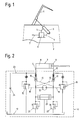
- Fig. 1 shows a schematic arrangement according to the present Invention in a vehicle
- Fig. 2 shows a schematic hydraulic Circuit diagram of an arrangement according to the invention.
- FIG. 1 The arrangement shown in Fig. 1 for hydraulic actuation of a Cover flap, a boot lid or other movable vehicle part 1 on a vehicle 2 has at least one double-acting hydraulic Working cylinder 3 on the one hand on the vehicle 2 and on the other the cover flap 1 is articulated.
- the workrooms not shown here of the working cylinder 3 are via lines 4, 5 with a hydraulic unit 6 connected, which via a connecting line 7 with the electrical Vehicle 2 electrical system is connected.
- movable hydraulic unit 6 may require the articulation of the working cylinder 3 on the vehicle and / or cover flap side also indirectly via levers, hinge arrangements or the like take place, the working cylinder 3 also being fixed relative to the vehicle 2 could be mounted.
- the 2 is the combination of hydraulic unit 6 and Lines 4, 5 connected cylinder 3 shown in more detail.
- the two working spaces 8, 9 of the working cylinder 3 are via the lines 4, 5 and each with a check valve 10, 11 arranged in the hydraulic unit 6 one side each of a switchable pressure source 12 (formed here Pump including drive motor) in connection.
- the two check valves 10, 11 are connected via lines 13, 14 and can be unlocked from each other. over one bias valve 15, 16 each, the two working spaces 8, 9 are parallel to the check valves 10, 11 in the tank 17 as soon as an adjustable Pressure levels are reached or exceeded.
- the preload valves 15, 16 are via lines 18, 19 and the pump side in front of the check valves 10, 11 prevailing pressure can be shut off hydraulically.
- the function of the arrangement shown is as in FIG. 2 illustrated explained.
- the Working cylinder 3 off or on.
- the motor of the pump of the pressure source 12 is energized, the pump runs and supplies pressure medium via the check valves 10 or 11 in the piston-side working space 8 or the rod-side Working room 9. This is on the same side via lines 18 and 19 such as the bias valve 15 or 16 controlled.
- the pressure in the work area 8 or 9 can be up to Build the required value.
- the cover flap 1 (Fig. 1) opens or closes hydraulically up to the stop in the working cylinder 3.
- the volume of the rod-side work space 9 flows when opening via the line 14 hydraulically controlled check valve 11 and the shuttle valve 20 in the tank 16 off.
- the hydraulic system delivers the total pressure relief valve 21 or 22 adjustable force.
- the pump runs until the cover flap 1 is open and is then switched off.
- a cover flap 1 according to FIG. 1 could be the inventive arrangement of course also for the actuation of vertical in the closed state
- Tailgates can be used for example a station wagon or a bus.
- Other application examples would be e.g. Vehicle doors, maintenance or ventilation flaps and the like.
Abstract
Description
Die Erfindung betrifft eine Anordnung zur hydraulischen Betätigung eines Heckdeckels, einer Abdeckklappe od. dgl. an einem Fahrzeug, mit zumindest einem doppeltwirkenden hydraulischen Arbeitszylinder, der einerseits am Fahrzeug und andererseits an der Abdeckklappe angelenkt ist und dessen Arbeitsräume über je ein Rückschlagventil mit jeweils einer Seite einer umschaltbaren Druckquelle in Verbindung stehen, wobei die beiden Rückschlagventile eine gegenseitige Entsperreinrichtung aufweisen und jeder der Arbeitsräume parallel zu den Rückschlagventilen über ein in den Tank absteuerndes Vorspannventil auf einem bestimmten Druckniveau gehalten ist.The invention relates to an arrangement for hydraulic actuation of a Rear cover, a cover flap or the like on a vehicle, with at least a double-acting hydraulic working cylinder, on the one hand on the Vehicle and on the other hand is hinged to the cover flap and its Workrooms each with a check valve with one side of each switchable pressure source are connected, the two check valves have a mutual unlocking device and each of the work rooms parallel to the non-return valves via a control valve in the tank Bias valve is kept at a certain pressure level.
Derartige Anordnungen sind bekannt und ermöglichen beispielsweise die automatische Betätigung von Fahrzeugtüren, Motorhauben, Wartungsklappen oder auch von Abdeckklappen des Kofferraumes oder eines ein Faltverdeck aufnehmenden Raumes. Durch die gegenseitig entsperrbaren Rückschlagventile wird sichergestellt, daß beim Ausschalten oder Ausfallen des Betriebsdruckes die Abdeckklappe in der jeweiligen Stellung hydraulisch gesperrt stehenbleibt, um unkontrollierte Bewegungen und damit einhergehende Gefahren auszuschalten. Das Vorspannventil ermöglicht eine kontrollierte Weiterbewegung der Abdeckklappe in diesem Zustand beispielsweise von Hand aus, um etwa ein Not-Schließen gegen eine vom Vorspannventil vorgegebene Kraft zu erlauben.Such arrangements are known and enable, for example, the automatic actuation of vehicle doors, bonnets, maintenance flaps or also of cover flaps of the trunk or of a folding roof Space. Through the mutually unlockable check valves ensures that when the operating pressure is switched off or fails, the The cover flap remains locked in the respective position in order to to eliminate uncontrolled movements and the associated dangers. The preload valve enables the cover flap to move in a controlled manner in this state, for example, by hand, such as an emergency closing to allow against a force specified by the preload valve.
Nachteilig bei der angeführten bekannten Anordnung der genannten Art ist insbesonders der Umstand, daß die beschriebene Notbetätigung nur im Zusammenhang mit einem volumsausgeglichenen Arbeitszylinder möglich ist, da es ansonsten Probleme mit dem Entfernen bzw. Zuführen von Hydraulikmedium zum kolben- bzw. stangenseitigen Arbeitsraum gibt. Ein einfaches Absteuern des überschüssigen, aus dem jeweiligen Arbeitsraum ausgeschobenen Volumens in den Tank wäre zwar noch möglich - Probleme gibt es aber mit dem im Notfall drucklosen Nachliefern von Hydraulikmedium in den anderen Arbeitsraum, da für die Anwendung in Fahrzeugen einerseits sehr dünne, flexible Leitungen verwendet werden müssen, die andererseits auch zufolge der gedrängten Unterbringungsmöglichkeiten relativ lang sind, sodaß der nachsaugende Arbeitsraum zumindest zum Teil mit ausgasender Luft gefüllt wird. Dies führt dann dazu, daß nach dem Auslassen der händisch notbetätigten Abdeckklappe diese undefiniert zurückfallen und Beschädigungen und Verletzungen hervorrufen kann.A disadvantage of the known arrangement mentioned of the type mentioned especially the fact that the described emergency operation only in context with a volume-balanced working cylinder is possible because it otherwise problems with the removal or supply of hydraulic medium to the piston or rod-side working space there. A simple shutdown of the excess volume ejected from the respective work area into the Tank would still be possible - but there are problems with it in an emergency unpressurized supply of hydraulic medium to the other work area, because for the application in vehicles uses very thin, flexible cables which, on the other hand, are also due to the crowded accommodation options are relatively long, so that the absorbing work area is at least partially filled with outgassing air. This then leads that after dropping the manually operated cover flap it is undefined can fall back and cause damage and injury.
Aufgabe der vorliegenden Erfindung ist es, eine bekannte Anordnung der eingangs beschriebenen Art so zu verbessern, daß die beschriebenen Nachteile vermieden werden und daß insbesonders auf einfache und sichere Weise eine Notbetätigung der Abdeckklappe auch bei den üblichen, auf Kolben- und Stangenseite unterschiedliche Volumina der Arbeitsräume aufweisenden Arbeitszylindern möglich wird.The object of the present invention is to provide a known arrangement of the Improve the type described above so that the disadvantages described to be avoided and that in particular in a simple and safe manner Emergency actuation of the cover flap also on the usual, on the piston and rod side different volumes of the working cylinders having working spaces becomes possible.
Diese Aufgabe wird bei einer Anordnung der eingangs genannten Art gemäß der Erfindung dadurch gelöst, daß zwischen zumindest einem Arbeitsraum, vorzugsweise dem kolbenseitigen Arbeitsraum, und dem zugehörigen entsperrbaren Rückschlagventil eine zum Tank führende, separate Nachsaugleitung einmündet, in welche ein zum Arbeitsraum hin öffnendes Rückschlagventil eingesetzt ist. Bei einem Ausfall des hydraulischen Arbeitsdruckes ist damit weiterhin eine einfache und sichere Notbetätigung der Abdeckklappe beispielsweise von Hand aus möglich. Bei dabei von Hand ausgezogenem Arbeitszylinder wird das stangenseitige Arbeitsraumvolumen in den Tank abgeschoben, wobei das fehlende Differenzvolumen über das Rückschlagventil aus dem Tank angesaugt wird. Da in der Nachsaugleitung keinerlei weitere hydraulische Elemente wie Ventile, Düsen, etc. angeordnet sind und die Leitung auch keine anderen Funktionen erfüllen muß, kann sie ganz auf die Nachsaugfunktion ausgelegt werden und so gestaltet sein, daß auch bei schnellstmöglicher manueller Betätigung des Heckdeckels, der Abdeckklappe od. dgl. ein Ansaugen von Hydraulikmedium ohne Ausgasen von Luft gewährleistet ist. Damit ist aber in weiterer Folge das sichere Halten des manuell bewegten Fahrzeugteils in der jeweiligen Stellung sichergestellt, da weder ausgegaste Luft komprimiert wird noch Hydraulikflüssigkeit in den Tank zurückfließen kann. This task is performed in accordance with an arrangement of the type mentioned solved the invention in that between at least one work space, preferably the piston-side working space, and the associated unlockable Check valve a separate suction line leading to the tank opens into which a non-return valve opens towards the work area is inserted. If there is a failure of the hydraulic working pressure furthermore a simple and safe emergency operation of the cover flap, for example possible by hand. With the working cylinder pulled out by hand the rod-side workspace volume is pushed into the tank, the missing differential volume is sucked out of the tank via the check valve becomes. Since no further hydraulic elements such as Valves, nozzles, etc. are arranged and the line no other Functions, it can be designed entirely for the suction function be and be designed so that even with the fastest possible manual Actuation of the trunk lid, the cover flap or the like Hydraulic medium is guaranteed without outgassing air. But that is in further consequence is the safe holding of the manually moved vehicle part in the position, since neither outgassed air is compressed hydraulic fluid can still flow back into the tank.
Selbstverständlich kann die Nachsaugleitung mit dem Rückschlagventil auch auf der Stangenseite des Arbeitszylinders vorgesehen sein und dabei das ungehinderte Nachsaugen von Hydraulikmedium beim manuellen Schließen der Abdeckklappe od. dgl. sowie das nachfolgende Sichern gegen unbeabsichtigtes Aufdrücken sicherstellen. Damit ist, speziell im Falle von das Öffnen unterstützenden oder bei entsprechender Stärke automatisch bewirkenden Gasfedern od. dgl., gewährleistet, daß auch beim Ausfall der Betätigungshydraulik die Abdeckklappe od. dgl. in der manuell eingestellten Position gehalten wird. Auch die Nachsaug- und Sicherungsfunktion für manuelles Öffnen und Schließen durch Vorsehen einer Nachsaugleitung mit Rückschlagventil auf sowohl der Stangen- als auch der Kolbenseite des Arbeitszylinders ist denkbar, alternativ dazu auch der Anschluß einer Nachsaugleitung mit Rückschlagventil an wechselweise eine der Leitungen zum Arbeitszylinder über ein Umschaltventil.Of course, the suction line with the check valve also be provided on the rod side of the working cylinder and the unimpeded suction of hydraulic medium when manually closing the Cover flap or the like. And the subsequent securing against unintentional Ensure press on. This is supportive, especially in the case of opening or with appropriate strength gas springs od. Like., Guarantees that even if the operating hydraulics fail Cover flap or the like is held in the manually set position. Also the suction and safety function for manual opening and closing by providing a suction line with a check valve on both the Rod as well as the piston side of the working cylinder is conceivable, alternatively also the connection of a suction line with a check valve alternately one of the lines to the working cylinder via a changeover valve.
In bevorzugter Ausgestaltung der Erfindung ist vorgesehen, daß die Nachsaugleitung zwischen dem jeweiligen Arbeitsraum und dem nächstliegenden hydraulischen Bauelement einmündet. Damit ist die unmittelbare und ungehinderte Nachsaugung von Hydraulikmedium aus dem Tank, unabhängig von der Ausstattung des automatischen Betätigungssystems, und deren optimale Auslegung auf ihre Funktion bei der manuellen Betätigung ermöglicht.In a preferred embodiment of the invention it is provided that the Suction line between the respective work area and the closest one hydraulic component opens. So that is immediate and unimpeded Suction of hydraulic medium from the tank, regardless of the Equipment of the automatic actuation system and its optimal design on their function in manual operation.
Die Erfindung wird im folgenden noch anhand der Zeichnungen näher erläutert. Fig. 1 zeigt dabei eine schematische Anordnung nach der vorliegenden Erfindung in einem Fahrzeug und Fig. 2 zeigt einen schematischen hydraulischen Schaltplan einer erfindungsgemäßen Anordnung.The invention will be explained in more detail below with reference to the drawings explained. Fig. 1 shows a schematic arrangement according to the present Invention in a vehicle and Fig. 2 shows a schematic hydraulic Circuit diagram of an arrangement according to the invention.
Die in Fig. 1 dargestellt Anordnung zur hydraulischen Betätigung einer
Abdeckklappe, eines Heckdeckels oder eines sonstigen beweglichen Fahrzeugteils
1 an einem Fahrzeug 2 weist zumindest einen doppeltwirkenden hydraulischen
Arbeitszylinder 3 auf, der einerseits am Fahrzeug 2 und andererseits an
der Abdeckklappe 1 angelenkt ist. Die hier nicht weiter dargestellten Arbeitsräume
des Arbeitszylinders 3 sind über Leitungen 4, 5 mit einem Hydraulikaggregat
6 verbunden, welches über eine Anschlußleitung 7 mit dem elektrischen
Bordnetz des Fahrzeuges 2 in Verbindung steht.The arrangement shown in Fig. 1 for hydraulic actuation of a
Cover flap, a boot lid or other movable vehicle part
1 on a
Anstelle der beidseitigen direkten Anlenkung des Arbeitszylinders 3,
welche natürlich entsprechend bewegliche Leitungen 4, 5 oder ein insgesamt
mit dem Arbeitszylinder 3 mitbewegbares Hydraulikaggregat 6 erfordert, könnte
die Anlenkung des Arbeitszylinders 3 auf der Fahrzeug- und/oder Abdeckklappenseite
auch indirekt über Hebel, Scharnieranordnungen oder dergleichen
erfolgen, wobei der Arbeitszylinder 3 auch relativ zum Fahrzeug 2 feststehend
montiert sein könnte.Instead of the direct linkage of the working
In der Fig. 2 ist die Kombination von Hydraulikaggregat 6 und über die
Leitungen 4, 5 verbundenem Arbeitszylinder 3 detaillierter dargestellt. Die
beiden Arbeitsräume 8, 9 des Arbeitszylinders 3 sind über die Leitungen 4, 5
und je ein im Hydraulikaggregat 6 angeordnetes Rückschlagventil 10, 11 mit
jeweils einer Seite einer umschaltbaren Druckquelle 12 (hier gebildet aus
Pumpe samt Antriebsmotor) in Verbindung. Die beiden Rückschlagventile 10, 11
sind dabei über Leitungen 13, 14 verbunden und gegenseitig entsperrbar. Über
je ein Vorspannventil 15, 16 sind die beiden Arbeitsräume 8, 9 parallel zu
den Rückschlagventilen 10, 11 in den Tank 17 abgesteuert, sobald ein einstellbares
Druckniveaus erreicht oder überschritten wird. Die Vorspannventile
15, 16 sind über Leitungen 18, 19 und den pumpenseitig vor den Rückschlagventilen
10, 11 herrschenden Druck hydraulisch absperrbar.2 is the combination of
Die in Fig. 1 ersichtliche Anschlußleitung 7, welche in Fig. 2 nicht
separat dargestellt ist, steuert den Motor der Pumpe der Druckquelle 12 und
ein Wechselventil 20 zwischen den über einstellbare Druckbegrenzungsventile
21, 22 zum Tank 17 führenden Leitungen. Weiters könnten über diese Anschlußleitung
7 auch beispielsweise Endschalter oder sonstige Stellungskontrollen
Signale zu nicht weiter dargestellten Steuereinheiten oder dergleichen
liefern.The connecting
In der Leitung 4 zum kolbenseitigen Arbeitsraum 8 des Arbeitszylinders 3
mündet eine Nachsaugleitung 23 mit einem zum Arbeitsraum 8 öffnenden Rückschlagventil
24, über welche Nachsaugleitung 23 beim manuellen Ausfahren des
Arbeitszylinders 3 Hydraulikflüssigkeit aus dem Tank 17 in den Arbeitsraum 8
nachgesaugt werden kann.In the line 4 to the piston-
Im folgenden wird die Funktion der dargestellten Anordnung wie in Fig. 2
dargestellt erläutert. Beim hydraulischen Öffnen bzw. Schließen fährt der
Arbeitszylinder 3 aus bzw. ein. Der Motor der Pumpe der Druckquelle 12 ist
bestromt, die Pumpe läuft und liefert Druckmedium über die Rückschlagventile
10 bzw. 11 in den kolbenseitigen Arbeitsraum 8 bzw. den stangenseitigen
Arbeitsraum 9. Über die Leitungen 18 bzw. 19 ist das auf der gleichen Seite
wie das jeweils durchströmte Rückschlagventil liegende Vorspannventil 15 oder
16 zugesteuert. Der Druck im Arbeitsraum 8 bzw. 9 kann sich bis auf den
erforderlichen Wert aufbauen. Die Abdeckklappe 1 (Fig. 1) öffnet oder
schließt hydraulisch bis zum Anschlag im Arbeitszylinder 3. Das Volumen des
stangenseitigen Arbeitsraumes 9 fließt beim Öffnen über das über die Leitung
14 hydraulisch aufgesteuerte Rückschlagventil 11 und das Wechselventil 20 in
den Tank 16 ab. Je nach Gegengewicht bzw. Gegenkraft an der Abdeckklappe 1
liefert die Hydraulik insgesamt die am Druckbegrenzungsventil 21 oder 22
einstellbare Kraft. Die Pumpe läuft bis die Abdeckklappe 1 geöffnet ist und
wird dann abgeschaltet.In the following, the function of the arrangement shown is as in FIG. 2
illustrated explained. When opening or closing hydraulically, the
Beim hydraulischen Schließen ist wieder der Motor der Pumpe der Druckquelle
12 bestromt, wobei hier nun Druckmedium über das Rückschlagventil 11
in den stangenseitigen Arbeitsraum 9 gefördert wird. Der Deckel 1 schließt
mit einer am Druckbegrenzungsventil 22 einstellbaren Kraft. Das aus dem
kolbenseitigen Arbeitsraum 8 abfließende Volumen fließt über das über die
Leitung 13 aufgesteuerte Rückschlagventil 10 sowie das Wechselventil 20 in
den Tank 16 ab. Die Schließkraft kann dabei nicht höher als am Druckbegrenzungsventil
22 eingestellt werden, womit leicht realisiert werden kann, daß
die Abdeckklappe 1 zur Not auch von Hand noch angehalten werden kann. Die
Abdeckklappe 1 wird beim Anhalten der hydraulischen Betätigung durch den an
den Vorspannventilen 15 und 16 eingestellten Druck gehalten.With hydraulic closing, the motor of the pump is the pressure source again
12 energized, here now pressure medium via the check valve 11
is promoted in the rod-
Beim Öffnen der Abdeckklappe 1 von Hand, beispielsweise bei Ausfall der
Druckquelle 12 zufolge fehlender Stromversorgung, kann diese mit relativ
geringem Kraftaufwand geöffnet werden. Es sind lediglich die Gewichtskraft
der Abdeckklappe 1 selbst sowie die Strömungswiderstände in der Hydraulik zu
überwinden. Eventuell im Fahrzeug eingebaute, an der Abdeckklappe 1 angreifende
Gasfedern wirken zusätzlich unterstützend. Das Druckmedium fließt durch
das wegen den fehlenden Drucks offene Vorspannventil 16 vom stangenseitigen
Arbeitsraum 9 nahezu drucklos und dadurch mit geringem erforderlichen Kraftaufwand
in den Tank 17 ab. Gleichzeitig wird mit geringstem Widerstand, weil
allein ein Rückschlagventil 24 vorgesehen und die Leitung 23 auf diesen
Zustand optimal auslegbar ist, Hydraulikflüssigkeit aus dem Tank 17 durch
diese Leitung 23 in den kolbenseitigen Arbeitsraum 8 nachgesaugt. Sobald die
manuelle Betätigung endet schließt das Rückschlagventil 24 und verhindert ein
Zurückströmen des Druckmediums in den Tank. Die möglichst widerstandsfreie
Ansaugung ist außerordentlich wichtig, damit die Abdeckklappe 1 nach einer
derartigen Notbetätigung auch stehen bleibt und nicht gegen einen Luftpolster
in diesem Arbeitsraum 8 zurückfallen kann, was ein großes Sicherheitsrisiko
darstellen könnte. Zufolge des Unterdrucks bei nicht gefülltem kolbenseitigen
Arbeitsraum würde nämlich Luft aus dem Druckmedium gelöst.When opening the cover flap 1 by hand, for example if the
Um die oben beschriebene Funktion alternativ oder zusätzlich auf der
Stangenseite des Arbeitszylinders 3 zu bieten und derart die Abdeckklappe 1
od. dgl. gegen Aufdrücken, beispielsweise durch das Gewicht der Abdeckklappe
1 kompensierende starke Gasfederanordnungen, zu sichern, kann die Nachsaugleitung
23 anstelle zur Leitung 4 zur Leitung 5 geführt sein, die den stangenseitigen
Arbeitsraum 9 mit Hydraulikmedium versorgt. Auch die Verbindung
beider Arbeitsräume 8, 9 mit dem Tank 17 über eine Nachsaugleitung mit
Rückschlagventil wäre möglich, wobei dann die Abdeckklappe 1 od. dgl. nach
manueller Betätigung bei inaktiver Betätigungsanordnung sicher in jeder
erreichten Stellung gehalten ist.To the function described above alternatively or additionally on the
To offer rod side of the working
Abgesehen von der dargestellten und beschriebenen Anordnung und Betätigung einer Abdeckklappe 1 gemäß Fig. 1 (beispielsweise an einem Kofferraum oder der Motorhaube eines PKW) könnte die erfindungsgemäße Anordnung natürlich auch zur Betätigung von im geschlossenen Zustand senkrechten Heckklappen beispielsweise eines Kombi oder eines Busses verwendet werden. Andere Anwendungsbeispiele wären z.B. Fahrzeugtüren, Wartungs- oder Lüftungsklappen und dergleichen mehr.Apart from the arrangement and operation shown and described a cover flap 1 according to FIG. 1 (for example on a trunk or the hood of a car) could be the inventive arrangement of course also for the actuation of vertical in the closed state Tailgates can be used for example a station wagon or a bus. Other application examples would be e.g. Vehicle doors, maintenance or ventilation flaps and the like.
Claims (2)
Applications Claiming Priority (2)
| Application Number | Priority Date | Filing Date | Title |
|---|---|---|---|
| AT0088298A AT405750B (en) | 1998-05-22 | 1998-05-22 | ARRANGEMENT FOR HYDRAULICALLY OPERATING A REAR LID |
| AT88298 | 1998-05-22 |
Publications (3)
| Publication Number | Publication Date |
|---|---|
| EP0959216A2 true EP0959216A2 (en) | 1999-11-24 |
| EP0959216A3 EP0959216A3 (en) | 2003-05-14 |
| EP0959216B1 EP0959216B1 (en) | 2004-09-01 |
Family
ID=3502006
Family Applications (1)
| Application Number | Title | Priority Date | Filing Date |
|---|---|---|---|
| EP99890103A Expired - Lifetime EP0959216B1 (en) | 1998-05-22 | 1999-03-24 | Assembly for hydraulically operating a tailgate |
Country Status (5)
| Country | Link |
|---|---|
| US (1) | US6217105B1 (en) |
| EP (1) | EP0959216B1 (en) |
| JP (1) | JP2000161306A (en) |
| AT (1) | AT405750B (en) |
| DE (1) | DE59910374D1 (en) |
Cited By (3)
| Publication number | Priority date | Publication date | Assignee | Title |
|---|---|---|---|---|
| WO2002061288A2 (en) * | 2001-01-29 | 2002-08-08 | Hoerbiger Hydraulik Gmbh | Hydraulic actuating system and check valve which can be hydraulically blocked |
| DE102016015093A1 (en) | 2016-12-17 | 2017-06-29 | Daimler Ag | Drive device for a wing element of a vehicle, as well as holding arrangement of such a wing element on a body of a vehicle |
| CN107905666A (en) * | 2017-11-07 | 2018-04-13 | 宁波汉商液压有限公司 | A kind of hydraulic system for controlling automobile power back door |
Families Citing this family (12)
| Publication number | Priority date | Publication date | Assignee | Title |
|---|---|---|---|---|
| NL1011852C2 (en) † | 1999-04-21 | 2000-10-24 | Applied Power Inc | Hydraulic control device for a vehicle cover cap assembly. |
| AT408792B (en) * | 1999-11-22 | 2002-03-25 | Hoerbiger Hydraulik | HYDRAULIC ACTUATING ARRANGEMENT |
| KR20020028320A (en) * | 2000-10-09 | 2002-04-17 | 이계안 | door opening and closing device for bus |
| DE10119340A1 (en) * | 2001-04-20 | 2002-10-31 | Stabilus Gmbh | Actuating system for a flap or the like |
| FR2834528B1 (en) * | 2002-01-04 | 2004-02-20 | France Design | DEVICE SUITABLE FOR CONTROLLING THE OPENING AND CLOSING OF A TRUNK HOOD |
| US6857686B2 (en) | 2003-02-06 | 2005-02-22 | Asc Incorporated | Two-way opening decklid for a convertible roof vehicle |
| US7198318B2 (en) * | 2003-03-24 | 2007-04-03 | Asc Incorporated | Retractable roof structural system |
| US20050006156A1 (en) * | 2003-07-10 | 2005-01-13 | Schambach Darren M. | Hood positioning apparatus and method |
| FI20060450L (en) * | 2006-05-09 | 2007-11-10 | Huhtasalo Jouko | System for positioning the actuator cylinder, system use and working machine |
| DE102017121501B3 (en) | 2017-09-15 | 2018-08-23 | Hoerbiger Automotive Komfortsysteme Gmbh | motor vehicle |
| DE102017121499B3 (en) | 2017-09-15 | 2018-08-16 | Hoerbiger Automotive Komfortsysteme Gmbh | motor vehicle |
| CN113216785B (en) * | 2021-05-28 | 2022-12-23 | 山东通华专用车辆股份有限公司 | Incompletely opened automatic lifting back door |
Citations (4)
| Publication number | Priority date | Publication date | Assignee | Title |
|---|---|---|---|---|
| US2467509A (en) * | 1944-11-28 | 1949-04-19 | Bendix Aviat Corp | Hydraulic system |
| US3266381A (en) * | 1964-12-14 | 1966-08-16 | Gen Motors Corp | Control valve for vehicle closure operator system |
| US5279119A (en) * | 1991-02-25 | 1994-01-18 | Wickes Manufacturing Company | Hydraulic lock and bypass for vehicle hydraulic system |
| EP0893605A1 (en) * | 1997-07-23 | 1999-01-27 | HOERBIGER GmbH | Hydraulic drive system |
Family Cites Families (11)
| Publication number | Priority date | Publication date | Assignee | Title |
|---|---|---|---|---|
| US4359119A (en) * | 1979-05-04 | 1982-11-16 | New York Development Consultants, Ltd. | Spring-assisted elongated mass over-center system |
| DE3151070C2 (en) * | 1981-12-23 | 1994-07-14 | Stabilus Gmbh | Safety gas spring for bonnets and / or trunk lids of motor vehicles |
| JPS60121115A (en) * | 1983-12-01 | 1985-06-28 | Toyota Motor Corp | Controller for power-operated convertible roof for car |
| DE3413380A1 (en) * | 1984-04-10 | 1985-10-17 | Dr.Ing.H.C. F. Porsche Ag, 7000 Stuttgart | DEVICE FOR OPENING AND CLOSING A TOP OF A MOTOR VEHICLE |
| US4688844A (en) * | 1984-04-18 | 1987-08-25 | Mazda Motor Corporation | Back door structures for motor vehicles |
| US4858981A (en) * | 1988-06-20 | 1989-08-22 | Post Herman D | Vehicle loading attachment |
| US5110175A (en) * | 1991-07-26 | 1992-05-05 | Wickes Manufacturing Company | Convertible with automatic window operation |
| AT399130B (en) * | 1992-03-18 | 1995-03-27 | Hoerbiger Fluidtechnik Gmbh | ARRANGEMENT FOR HYDRAULICALLY OPERATING A VEHICLE TOP |
| NL9401191A (en) * | 1994-07-20 | 1996-03-01 | Applied Power Inc | Hydraulic circuit. |
| KR970005252U (en) * | 1995-07-19 | 1997-02-19 | Roof rail end cover combined structure of the car | |
| AT403785B (en) * | 1996-04-24 | 1998-05-25 | Hoerbiger Gmbh | HYDRAULIC ACTUATING ARRANGEMENT |
-
1998
- 1998-05-22 AT AT0088298A patent/AT405750B/en not_active IP Right Cessation
-
1999
- 1999-03-24 EP EP99890103A patent/EP0959216B1/en not_active Expired - Lifetime
- 1999-03-24 DE DE59910374T patent/DE59910374D1/en not_active Expired - Lifetime
- 1999-05-19 JP JP11139115A patent/JP2000161306A/en active Pending
- 1999-05-21 US US09/316,018 patent/US6217105B1/en not_active Expired - Fee Related
Patent Citations (4)
| Publication number | Priority date | Publication date | Assignee | Title |
|---|---|---|---|---|
| US2467509A (en) * | 1944-11-28 | 1949-04-19 | Bendix Aviat Corp | Hydraulic system |
| US3266381A (en) * | 1964-12-14 | 1966-08-16 | Gen Motors Corp | Control valve for vehicle closure operator system |
| US5279119A (en) * | 1991-02-25 | 1994-01-18 | Wickes Manufacturing Company | Hydraulic lock and bypass for vehicle hydraulic system |
| EP0893605A1 (en) * | 1997-07-23 | 1999-01-27 | HOERBIGER GmbH | Hydraulic drive system |
Cited By (4)
| Publication number | Priority date | Publication date | Assignee | Title |
|---|---|---|---|---|
| WO2002061288A2 (en) * | 2001-01-29 | 2002-08-08 | Hoerbiger Hydraulik Gmbh | Hydraulic actuating system and check valve which can be hydraulically blocked |
| WO2002061288A3 (en) * | 2001-01-29 | 2004-02-12 | Hoerbiger Hydraulik | Hydraulic actuating system and check valve which can be hydraulically blocked |
| DE102016015093A1 (en) | 2016-12-17 | 2017-06-29 | Daimler Ag | Drive device for a wing element of a vehicle, as well as holding arrangement of such a wing element on a body of a vehicle |
| CN107905666A (en) * | 2017-11-07 | 2018-04-13 | 宁波汉商液压有限公司 | A kind of hydraulic system for controlling automobile power back door |
Also Published As
| Publication number | Publication date |
|---|---|
| JP2000161306A (en) | 2000-06-13 |
| EP0959216A3 (en) | 2003-05-14 |
| AT405750B (en) | 1999-11-25 |
| US6217105B1 (en) | 2001-04-17 |
| ATA88298A (en) | 1999-03-15 |
| EP0959216B1 (en) | 2004-09-01 |
| DE59910374D1 (en) | 2004-10-07 |
Similar Documents
| Publication | Publication Date | Title |
|---|---|---|
| EP0803630B1 (en) | Hydraulic operating device | |
| EP0959216B1 (en) | Assembly for hydraulically operating a tailgate | |
| AT399130B (en) | ARRANGEMENT FOR HYDRAULICALLY OPERATING A VEHICLE TOP | |
| DE102012011273B3 (en) | Mobile big fan | |
| EP1101692B1 (en) | Hydraulic operating device | |
| EP0959217B1 (en) | Assembly for hydraulically operating a tailgate | |
| EP1776526A1 (en) | Hydraulic system for opening and closing wings of a truck | |
| AT408208B (en) | ARRANGEMENT FOR HYDRAULICALLY OPERATING A MOVING PART ON VEHICLES, IN PARTICULAR A COVER, A REAR COVER, A HATCH, OR THE LIKE. | |
| DE102005005891B4 (en) | Door with door brake | |
| AT396613B (en) | HYDRAULIC OPERATING ARRANGEMENT FOR A VEHICLE TAIL | |
| AT406072B (en) | HYDRAULIC ACTUATOR ARRANGEMENT | |
| EP1404976B1 (en) | Hydraulic actuating system and check valve which can be hydraulically blocked | |
| DE10220455B4 (en) | Hydraulic actuator for a hood with associated latch | |
| EP1162375A2 (en) | Actuation arrangement for swivelling parts of vehicles | |
| AT405752B (en) | ARRANGEMENT FOR HYDRAULICALLY OPERATING A REAR LID | |
| AT405751B (en) | ARRANGEMENT FOR HYDRAULICALLY OPERATING A REAR LID | |
| EP1589168A1 (en) | Actuating device for an emergency unlocking device for doors of vehicles for the public transport | |
| WO2021165150A1 (en) | Hydraulic servo actuator | |
| AT406357B (en) | ARRANGEMENT FOR HYDRAULICALLY OPERATING A COVER, A REAR COVER OD. DGL. | |
| DE102017121499B3 (en) | motor vehicle | |
| DE102017121501B3 (en) | motor vehicle | |
| AT409399B (en) | HYDRAULIC ACTUATING ARRANGEMENT | |
| DE10023073B4 (en) | Protection element drive system | |
| DE102007015820A1 (en) | Hydraulically actuated loading platforms e.g. for cargo vehicle, has structure for mounting on vehicle load and which has connected pivoting arm with support plateau provided at outer end of boom arm | |
| DE102011078396A1 (en) | Drive for opening or closing movable leaf of door or window, has output part that is operatively connected to wing of door or window, and hydraulic pump, in the output part, is driven by drive motor |
Legal Events
| Date | Code | Title | Description |
|---|---|---|---|
| PUAI | Public reference made under article 153(3) epc to a published international application that has entered the european phase |
Free format text: ORIGINAL CODE: 0009012 |
|
| AK | Designated contracting states |
Kind code of ref document: A2 Designated state(s): AT BE CH CY DE DK ES FI FR GB GR IE IT LI LU MC NL PT SE |
|
| AX | Request for extension of the european patent |
Free format text: AL;LT;LV;MK;RO;SI |
|
| PUAL | Search report despatched |
Free format text: ORIGINAL CODE: 0009013 |
|
| AK | Designated contracting states |
Designated state(s): AT BE CH CY DE DK ES FI FR GB GR IE IT LI LU MC NL PT SE |
|
| AX | Request for extension of the european patent |
Extension state: AL LT LV MK RO SI |
|
| RIC1 | Information provided on ipc code assigned before grant |
Ipc: 7E 05F 15/00 B Ipc: 7B 62D 25/12 B Ipc: 7E 05F 15/04 A |
|
| 17P | Request for examination filed |
Effective date: 20030604 |
|
| AKX | Designation fees paid |
Designated state(s): DE FR IT |
|
| GRAP | Despatch of communication of intention to grant a patent |
Free format text: ORIGINAL CODE: EPIDOSNIGR1 |
|
| GRAS | Grant fee paid |
Free format text: ORIGINAL CODE: EPIDOSNIGR3 |
|
| GRAA | (expected) grant |
Free format text: ORIGINAL CODE: 0009210 |
|
| AK | Designated contracting states |
Kind code of ref document: B1 Designated state(s): DE FR IT |
|
| PG25 | Lapsed in a contracting state [announced via postgrant information from national office to epo] |
Ref country code: IT Free format text: LAPSE BECAUSE OF FAILURE TO SUBMIT A TRANSLATION OF THE DESCRIPTION OR TO PAY THE FEE WITHIN THE PRE;WARNING: LAPSES OF ITALIAN PATENTS WITH EFFECTIVE DATE BEFORE 2007 MAY HAVE OCCURRED AT ANY TIME BEFORE 2007. THE CORRECT EFFECTIVE DATE MAY BE DIFFERENT FROM THE ONE RECORDED.SCRIBED TIME-LIMIT Effective date: 20040901 |
|
| REG | Reference to a national code |
Ref country code: IE Ref legal event code: FG4D Free format text: GERMAN |
|
| REF | Corresponds to: |
Ref document number: 59910374 Country of ref document: DE Date of ref document: 20041007 Kind code of ref document: P |
|
| REG | Reference to a national code |
Ref country code: IE Ref legal event code: FD4D |
|
| PLBE | No opposition filed within time limit |
Free format text: ORIGINAL CODE: 0009261 |
|
| STAA | Information on the status of an ep patent application or granted ep patent |
Free format text: STATUS: NO OPPOSITION FILED WITHIN TIME LIMIT |
|
| ET | Fr: translation filed | ||
| 26N | No opposition filed |
Effective date: 20050602 |
|
| PGFP | Annual fee paid to national office [announced via postgrant information from national office to epo] |
Ref country code: FR Payment date: 20090303 Year of fee payment: 11 |
|
| REG | Reference to a national code |
Ref country code: FR Ref legal event code: ST Effective date: 20101130 |
|
| PG25 | Lapsed in a contracting state [announced via postgrant information from national office to epo] |
Ref country code: FR Free format text: LAPSE BECAUSE OF NON-PAYMENT OF DUE FEES Effective date: 20100331 |
|
| PGFP | Annual fee paid to national office [announced via postgrant information from national office to epo] |
Ref country code: DE Payment date: 20150528 Year of fee payment: 17 |
|
| REG | Reference to a national code |
Ref country code: DE Ref legal event code: R119 Ref document number: 59910374 Country of ref document: DE |
|
| PG25 | Lapsed in a contracting state [announced via postgrant information from national office to epo] |
Ref country code: DE Free format text: LAPSE BECAUSE OF NON-PAYMENT OF DUE FEES Effective date: 20161001 |