EP0959005A2 - Robinet de dosage - Google Patents
Robinet de dosage Download PDFInfo
- Publication number
- EP0959005A2 EP0959005A2 EP99109419A EP99109419A EP0959005A2 EP 0959005 A2 EP0959005 A2 EP 0959005A2 EP 99109419 A EP99109419 A EP 99109419A EP 99109419 A EP99109419 A EP 99109419A EP 0959005 A2 EP0959005 A2 EP 0959005A2
- Authority
- EP
- European Patent Office
- Prior art keywords
- housing
- cam
- dosing
- cavity
- openings
- Prior art date
- Legal status (The legal status is an assumption and is not a legal conclusion. Google has not performed a legal analysis and makes no representation as to the accuracy of the status listed.)
- Granted
Links
- 235000013618 yogurt Nutrition 0.000 claims abstract description 4
- 239000012459 cleaning agent Substances 0.000 claims description 2
- 230000009969 flowable effect Effects 0.000 claims description 2
- 239000000463 material Substances 0.000 claims description 2
- 239000007787 solid Substances 0.000 claims description 2
- 239000007788 liquid Substances 0.000 abstract 1
- 239000000126 substance Substances 0.000 abstract 1
- 238000004140 cleaning Methods 0.000 description 3
- 238000000034 method Methods 0.000 description 3
- 239000003599 detergent Substances 0.000 description 2
- 235000013399 edible fruits Nutrition 0.000 description 2
- 206010010774 Constipation Diseases 0.000 description 1
- 238000004033 diameter control Methods 0.000 description 1
- 238000004806 packaging method and process Methods 0.000 description 1
- 239000011343 solid material Substances 0.000 description 1
- XLYOFNOQVPJJNP-UHFFFAOYSA-N water Substances O XLYOFNOQVPJJNP-UHFFFAOYSA-N 0.000 description 1
Images

Classifications
-
- F—MECHANICAL ENGINEERING; LIGHTING; HEATING; WEAPONS; BLASTING
- F04—POSITIVE - DISPLACEMENT MACHINES FOR LIQUIDS; PUMPS FOR LIQUIDS OR ELASTIC FLUIDS
- F04B—POSITIVE-DISPLACEMENT MACHINES FOR LIQUIDS; PUMPS
- F04B7/00—Piston machines or pumps characterised by having positively-driven valving
- F04B7/0003—Piston machines or pumps characterised by having positively-driven valving the distribution member forming both the inlet and discharge distributor for one single pumping chamber
- F04B7/0011—Piston machines or pumps characterised by having positively-driven valving the distribution member forming both the inlet and discharge distributor for one single pumping chamber and having an oscillating movement
-
- F—MECHANICAL ENGINEERING; LIGHTING; HEATING; WEAPONS; BLASTING
- F04—POSITIVE - DISPLACEMENT MACHINES FOR LIQUIDS; PUMPS FOR LIQUIDS OR ELASTIC FLUIDS
- F04B—POSITIVE-DISPLACEMENT MACHINES FOR LIQUIDS; PUMPS
- F04B13/00—Pumps specially modified to deliver fixed or variable measured quantities
Definitions
- the invention relates to a metering valve on metering pumps according to Preamble of claim 1.
- a metering valve of this type in particular for metering free-flowing metered solid material containing pieces, such as jam, yoghurt or the like, is known from DE-A-195 04 546 C1.
- This known metering valve also works like a so-called rotary slide valve (see, for example, US-A-3,228,412), but in such a way that the cam, similar to a finger held in front of an opening, closes the feed opening and pivots it for the purpose of opening and thereby a relatively large part of the housing space is released, whereby, as has been shown, the metered-in filling material can flow around the cam in the open position without any risk of clogging.
- the actual metering is carried out by correspondingly timed actuation coordination of the metering valve and a metering pump arranged above the opening of the inflow channel on the valve housing, which is not particularly shown in DE-A-195 04 546.
- This metering valve works absolutely satisfactorily with regard to the requirement to avoid blockages in the case of difficult metered items of the above-mentioned type and to create a large flow space in the housing space when in the open position.
- the disadvantage here is that two such metering valves, which are not exactly cheap, must be assigned to a metering pump, namely one for the suction process and one for the exhaust process.
- the arrangement of two such metering valves for each metering pump requires space in the area above the filling station, for example a so-called FFS packaging machine, and also a corresponding double drive effort for two such metering valves.
- the invention is accordingly and starting from the metering valve type mentioned the task, while maintaining of its benefits including easy cleaning to redesign and improve such a metering valve, that one for a dosing pump with only one dosing valve for the Suction and exhaust process comes out, and also if necessary Suction and discharge openings of the metering valve at the same time should be lockable.
- the locking part only in permanent metering operation a very short pendulum movement between the openings of the inlet and Drain channels has to perform, the closing part due its closing surface dimension for both openings at the same time be brought into the closed position, for which the minimum dimension the closing surface is sufficient, the possible Maximum dimensioning finds its limit in that during suction and expelling the flow paths to and from the intake and Ejection opening in the housing can be flowed through as optimally as possible.
- the two inflow and outflow channels are preferably vertical and parallel arranged side by side in the housing, if possible only slightly curved flow paths in the valve from the suction side to the Pump and reach from this to the discharge opening.
- the metering valve according to the invention and its advantageous embodiments are subsequently based on the graphic Representation of exemplary embodiments explained in more detail.
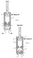
- the metering valve in particular intended for metering flowable, lumpy solid parts, such as jam, yogurt or the like, still consists of a housing 2 containing inflow and outflow channels 9, 10 with a housing in a with respect to the diameter D of Inflow and outflow channels 9, 10 larger diameter, cylindrical cavity 8 of the housing 2 pivotable closing part 1.
- This closing part 1 is designed as the head of a protruding in the housing 2 sealed, with respect to the diameter D1 of the cavity 8 smaller diameter control shaft 3.
- the actual closing surface 6 of the closing part 1 extends parallel to the cylindrical wall 7 of the cavity 8, and the closing part 1 is designed in the form of a cam 5, which is oriented to one side with respect to the pivot axis 4 of the actuating shaft 3.
- the radius R of the closing surface 6 of the cam 5 is dimensioned somewhat smaller than the radius R 'of the cavity 8 outside the region of the cylindrical arrangement plane ZE ' of both openings 9 ' , 10 ' .
- the two inflow and outflow channels 9, 10 are arranged in the housing 2 essentially opposite a pump suction and discharge opening 11.
- the two mutually adjacent openings 9 ' , 10 ' of the inflow and outflow channels 9, 10 spaced apart by an intermediate web 12 are arranged in the cylindrical adjustment plane ZE of the closing surface 6 of the cam 5.
- the closing surface 6 is dimensioned in its arc length L such that the two openings 9 ' , 10 ' are at least closed with a corresponding position of the cam 5 (total closed position according to FIG. 4).
- the maximum possible arc length L extends from one or the other opening edge 11 'of the pump suction and discharge opening 11 to the respective inner opening edge 9''', 10 '''of one or the other opening 9', 10 '(see FIG. 5 ).
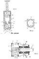
- Drainage channels 9, 10, not as shown in FIGS. 1 to 4 mandatory vertically opposite the suction and discharge opening 11 and must be arranged parallel to each other, which is preferred is, but also, as shown in Fig.6, with appropriate Design of the bottom of the housing can be arranged can.
- the radius R of the closing surface 6 of the cam 5 is dimensioned smaller than the radius R 'of the cavity 8 outside the area of the dosing valve according to the invention, as mentioned above cylindrical arrangement plane ZE 'of the openings 9 ' , 10 'of the two inflow and outflow channels 9, 10, but here in the area outside the arrangement plane ZE', specifically in the middle, the pump suction and discharge opening 11 is arranged.
- both the piston K of the metering pump P and the closing part 1 of the metering valve can be flushed around freely. Due to the given total closability of the metering valve (see FIG.
- an advantageous further development consists in providing on the housing 2 a closable cleaning agent connection 13 leading to the cavity 8. Regardless of whether the detergent is supplied to the top of the pump P through its connection 13 'or vice versa at the bottom of the detergent connection 13 of the metering valve, the pump and metering valve can be rinsed separately and / or sterilized for example when changing the product .
- both the suction and the ejection of the contents of gusset spaces Z or "dead water gussets" advantageously result in free and largely smooth flow-through spaces or flow-through channels in the housing 2, which with regard to, for example, .
- Coarse pieces of fruit are advantageous with regard to the risk of constipation.
- FIG. 7 Only for the sake of completeness is a longitudinal section in FIG. 7 represented by the metering valve, which is also in the present Case consists of two parts, i.e. from the to the drive side completely open housing 2, which on this side by the attachable bearing part LT for the closing part 1 completed becomes.
- the bearing part In the case of sterile operation, the bearing part is LT with connections and channels AK for the passage of a suitable Provide sterile.
Landscapes
- Engineering & Computer Science (AREA)
- Mechanical Engineering (AREA)
- General Engineering & Computer Science (AREA)
- Containers And Packaging Bodies Having A Special Means To Remove Contents (AREA)
- Closures For Containers (AREA)
- Rotary Pumps (AREA)
- Reciprocating Pumps (AREA)
- Devices For Dispensing Beverages (AREA)
Applications Claiming Priority (2)
| Application Number | Priority Date | Filing Date | Title |
|---|---|---|---|
| DE19822430A DE19822430C1 (de) | 1998-05-19 | 1998-05-19 | Dosierventil an Dosierpumpen |
| DE19822430 | 1998-05-19 |
Publications (3)
| Publication Number | Publication Date |
|---|---|
| EP0959005A2 true EP0959005A2 (fr) | 1999-11-24 |
| EP0959005A3 EP0959005A3 (fr) | 2000-10-25 |
| EP0959005B1 EP0959005B1 (fr) | 2004-03-17 |
Family
ID=7868282
Family Applications (1)
| Application Number | Title | Priority Date | Filing Date |
|---|---|---|---|
| EP99109419A Expired - Lifetime EP0959005B1 (fr) | 1998-05-19 | 1999-05-11 | Robinet de dosage |
Country Status (3)
| Country | Link |
|---|---|
| US (1) | US6179587B1 (fr) |
| EP (1) | EP0959005B1 (fr) |
| DE (1) | DE19822430C1 (fr) |
Cited By (3)
| Publication number | Priority date | Publication date | Assignee | Title |
|---|---|---|---|---|
| WO2000068078A1 (fr) * | 1999-05-11 | 2000-11-16 | Peter Owen Davies | Dispositif de dosage de fluides |
| WO2002031357A3 (fr) * | 2000-10-10 | 2002-09-06 | Beckman Coulter Inc | Dispositif servant a deplacer un fluide equipe d'une soupape integree |
| WO2016059551A3 (fr) * | 2014-10-13 | 2016-06-09 | Alfa S.R.L. | Pompe volumétrique et groupe de pompage pour produits fluides et procédé d'utilisation de ceux-ci |
Families Citing this family (8)
| Publication number | Priority date | Publication date | Assignee | Title |
|---|---|---|---|---|
| RU2180708C1 (ru) * | 2000-08-18 | 2002-03-20 | Открытое акционерное общество "Машиностроительный завод "АРСЕНАЛ" | Насос для густотекучих масс |
| GB0201103D0 (en) * | 2002-01-18 | 2002-03-06 | Mount Packaging Systems Ltd | Liquid dispensing pump |
| CA2519196A1 (fr) * | 2003-03-27 | 2004-10-14 | Swf Companies, Inc. | Formeuse-remplisseuse-scelleuse rapide a action continue |
| KR100996576B1 (ko) * | 2003-05-09 | 2010-11-24 | 주식회사 탑 엔지니어링 | 액정적하장치 및 액정적하방법 |
| CN101144466B (zh) * | 2007-11-15 | 2010-04-21 | 齐玉符 | 差动定量泵 |
| KR20120082989A (ko) * | 2011-01-17 | 2012-07-25 | 삼성전자주식회사 | 세탁기 |
| FR3006407B1 (fr) * | 2013-06-04 | 2015-07-17 | Capsum | Vanne a boisseau, dispositif de dosage d'un fluide et procede de dosage associes |
| CN105020130A (zh) * | 2015-08-02 | 2015-11-04 | 黄锦成 | 计量泵的三通计量球阀 |
Citations (2)
| Publication number | Priority date | Publication date | Assignee | Title |
|---|---|---|---|---|
| US3228412A (en) | 1962-07-16 | 1966-01-11 | Bartelt Engineering Co Inc | Dispensing valve having particular cleaning means |
| DE19504546C1 (de) | 1995-02-11 | 1996-08-01 | Hassia Verpackung Ag | Dosierventil an Dosierpumpen |
Family Cites Families (5)
| Publication number | Priority date | Publication date | Assignee | Title |
|---|---|---|---|---|
| US2827207A (en) * | 1954-05-04 | 1958-03-18 | Robert R Sprole | Fluid measuring mechanism for filling machines |
| US3266435A (en) * | 1963-12-09 | 1966-08-16 | Smith Eugene | Pump for semi-fluid material |
| DE6941284U (de) * | 1969-10-23 | 1970-02-19 | Huennebeck Gmbh | Pumpe zum foerdern dickfluessiger stoffe |
| US4457348A (en) * | 1982-07-07 | 1984-07-03 | Mueller Martin J | Food product fill pump |
| FR2671398B1 (fr) * | 1991-01-03 | 1995-09-08 | Atelier Etudes Realisa Automat | Dispositif de dosage et de distribution d'une matiere pateuse. |
-
1998
- 1998-05-19 DE DE19822430A patent/DE19822430C1/de not_active Expired - Fee Related
-
1999
- 1999-05-11 EP EP99109419A patent/EP0959005B1/fr not_active Expired - Lifetime
- 1999-05-18 US US09/313,399 patent/US6179587B1/en not_active Expired - Fee Related
Patent Citations (2)
| Publication number | Priority date | Publication date | Assignee | Title |
|---|---|---|---|---|
| US3228412A (en) | 1962-07-16 | 1966-01-11 | Bartelt Engineering Co Inc | Dispensing valve having particular cleaning means |
| DE19504546C1 (de) | 1995-02-11 | 1996-08-01 | Hassia Verpackung Ag | Dosierventil an Dosierpumpen |
Cited By (6)
| Publication number | Priority date | Publication date | Assignee | Title |
|---|---|---|---|---|
| WO2000068078A1 (fr) * | 1999-05-11 | 2000-11-16 | Peter Owen Davies | Dispositif de dosage de fluides |
| WO2002031357A3 (fr) * | 2000-10-10 | 2002-09-06 | Beckman Coulter Inc | Dispositif servant a deplacer un fluide equipe d'une soupape integree |
| US6520755B1 (en) | 2000-10-10 | 2003-02-18 | Beckman Coulter, Inc. | Fluid-moving device with integrated valve |
| WO2016059551A3 (fr) * | 2014-10-13 | 2016-06-09 | Alfa S.R.L. | Pompe volumétrique et groupe de pompage pour produits fluides et procédé d'utilisation de ceux-ci |
| AU2015332105B2 (en) * | 2014-10-13 | 2019-06-20 | Alfa S.R.L. | Positive-displacement pump and pumping group for fluid products and method for the use thereof |
| US11053930B2 (en) | 2014-10-13 | 2021-07-06 | Alfa S. R. L. | Positive-displacement pump and pumping group for fluid products and method for the use thereof |
Also Published As
| Publication number | Publication date |
|---|---|
| DE19822430C1 (de) | 2000-02-10 |
| EP0959005B1 (fr) | 2004-03-17 |
| EP0959005A3 (fr) | 2000-10-25 |
| US6179587B1 (en) | 2001-01-30 |
Similar Documents
| Publication | Publication Date | Title |
|---|---|---|
| EP3765180B1 (fr) | Dispositif de mélange pourvu d'un couvercle de fermeture en deux parties | |
| DE10110888A1 (de) | Dosierpumpenspender mit wenigstens zwei Dosierpumpen | |
| DE10359779A1 (de) | Füllelement sowie Füllmaschine mit derartigen Füllelementen | |
| EP0959005B1 (fr) | Robinet de dosage | |
| DE3707779A1 (de) | Vorrichtung zum herstellen von speiseeis, milchshake oder gefrorenen suessspeisen aus einem fliessfaehigen ansatz | |
| DE29909542U1 (de) | Füllventil für die Befüllung von insbesondere Flachbeutelverpackungen | |
| EP3765183B1 (fr) | Dispositif servant à transformer un déplacement linéaire dans un système stationnaire en un déplacement de rotation autour d'un axe de pivotement dans un système tournant autour d'un axe de rotation | |
| EP0265597A2 (fr) | Appareil de remplissage de récipients avec des doses déterminées de produits liquides ou pâteux | |
| DE19537303B4 (de) | Vorrichtung zum Homogenisieren fließfähiger Stoffe | |
| DE102008022398A1 (de) | Füllelement sowie Füllmaschine mit derartigen Füllelementen | |
| EP0540944B1 (fr) | Pompe doseuse pour produits à haute viscosité | |
| DE3204611A1 (de) | Fuellmaschine | |
| DE2233335A1 (de) | Absperrmechanismus an einem abflussrohr bei saemaschinen | |
| EP1527678A1 (fr) | Mélangeur | |
| DE3206141A1 (de) | Steuerventil fuer eine dosiereinrichtung zur dosierung von fluessigen medien, insbesondere von nahrungsmitteln | |
| DE19504546C1 (de) | Dosierventil an Dosierpumpen | |
| DE69504044T2 (de) | Selbstschliessende abgabevorrichtung | |
| DE19960221C2 (de) | Zellenradschleuse mit verbesserter Abdichtung gegen Leckluft | |
| DE69624074T2 (de) | Durchflusswegwählvorrichtung | |
| DE68917868T2 (de) | Abgabe - Vorrichtung und Verfahren. | |
| DE666373C (de) | Mit Messvorrichtung versehener Ausgiesser fuer Flaschen usw. | |
| EP2112122A2 (fr) | Récipient | |
| DE2303736C3 (de) | Durchflußsteuergerät für eine pneumatische Förderrinne | |
| DE10218164B4 (de) | Dosierer und Abfüllanlage, insbesondere für pastöse Lebensmittel | |
| DE2038010A1 (en) | Sausage meat filler |
Legal Events
| Date | Code | Title | Description |
|---|---|---|---|
| PUAI | Public reference made under article 153(3) epc to a published international application that has entered the european phase |
Free format text: ORIGINAL CODE: 0009012 |
|
| AK | Designated contracting states |
Kind code of ref document: A2 Designated state(s): FR GB IT |
|
| AX | Request for extension of the european patent |
Free format text: AL;LT;LV;MK;RO;SI |
|
| PUAL | Search report despatched |
Free format text: ORIGINAL CODE: 0009013 |
|
| AK | Designated contracting states |
Kind code of ref document: A3 Designated state(s): AT BE CH CY DE DK ES FI FR GB GR IE IT LI LU MC NL PT SE |
|
| AX | Request for extension of the european patent |
Free format text: AL;LT;LV;MK;RO;SI |
|
| RIC1 | Information provided on ipc code assigned before grant |
Free format text: 7B 65B 39/00 A, 7F 04B 7/00 B, 7F 04B 13/00 B |
|
| 17P | Request for examination filed |
Effective date: 20010217 |
|
| AKX | Designation fees paid |
Free format text: FR GB IT |
|
| GRAP | Despatch of communication of intention to grant a patent |
Free format text: ORIGINAL CODE: EPIDOSNIGR1 |
|
| GRAS | Grant fee paid |
Free format text: ORIGINAL CODE: EPIDOSNIGR3 |
|
| GRAA | (expected) grant |
Free format text: ORIGINAL CODE: 0009210 |
|
| AK | Designated contracting states |
Kind code of ref document: B1 Designated state(s): FR GB IT |
|
| PG25 | Lapsed in a contracting state [announced via postgrant information from national office to epo] |
Ref country code: IT Free format text: LAPSE BECAUSE OF FAILURE TO SUBMIT A TRANSLATION OF THE DESCRIPTION OR TO PAY THE FEE WITHIN THE PRE;WARNING: LAPSES OF ITALIAN PATENTS WITH EFFECTIVE DATE BEFORE 2007 MAY HAVE OCCURRED AT ANY TIME BEFORE 2007. THE CORRECT EFFECTIVE DATE MAY BE DIFFERENT FROM THE ONE RECORDED.SCRIBED TIME-LIMIT Effective date: 20040317 |
|
| REG | Reference to a national code |
Ref country code: GB Ref legal event code: FG4D Free format text: NOT ENGLISH |
|
| GBT | Gb: translation of ep patent filed (gb section 77(6)(a)/1977) |
Effective date: 20040317 |
|
| PG25 | Lapsed in a contracting state [announced via postgrant information from national office to epo] |
Ref country code: GB Free format text: LAPSE BECAUSE OF NON-PAYMENT OF DUE FEES Effective date: 20040617 |
|
| ET | Fr: translation filed | ||
| PLBE | No opposition filed within time limit |
Free format text: ORIGINAL CODE: 0009261 |
|
| STAA | Information on the status of an ep patent application or granted ep patent |
Free format text: STATUS: NO OPPOSITION FILED WITHIN TIME LIMIT |
|
| PG25 | Lapsed in a contracting state [announced via postgrant information from national office to epo] |
Ref country code: FR Free format text: LAPSE BECAUSE OF NON-PAYMENT OF DUE FEES Effective date: 20050131 |
|
| GBPC | Gb: european patent ceased through non-payment of renewal fee |
Effective date: 20040617 |
|
| REG | Reference to a national code |
Ref country code: FR Ref legal event code: ST |
|
| 26N | No opposition filed |
Effective date: 20041220 |