EP0959005A2 - Metering valve - Google Patents
Metering valve Download PDFInfo
- Publication number
- EP0959005A2 EP0959005A2 EP99109419A EP99109419A EP0959005A2 EP 0959005 A2 EP0959005 A2 EP 0959005A2 EP 99109419 A EP99109419 A EP 99109419A EP 99109419 A EP99109419 A EP 99109419A EP 0959005 A2 EP0959005 A2 EP 0959005A2
- Authority
- EP
- European Patent Office
- Prior art keywords
- housing
- cam
- dosing
- cavity
- openings
- Prior art date
- Legal status (The legal status is an assumption and is not a legal conclusion. Google has not performed a legal analysis and makes no representation as to the accuracy of the status listed.)
- Granted
Links
- 235000013618 yogurt Nutrition 0.000 claims abstract description 4
- 239000012459 cleaning agent Substances 0.000 claims description 2
- 230000009969 flowable effect Effects 0.000 claims description 2
- 239000000463 material Substances 0.000 claims description 2
- 239000007787 solid Substances 0.000 claims description 2
- 239000007788 liquid Substances 0.000 abstract 1
- 239000000126 substance Substances 0.000 abstract 1
- 238000004140 cleaning Methods 0.000 description 3
- 238000000034 method Methods 0.000 description 3
- 239000003599 detergent Substances 0.000 description 2
- 235000013399 edible fruits Nutrition 0.000 description 2
- 206010010774 Constipation Diseases 0.000 description 1
- 238000004033 diameter control Methods 0.000 description 1
- 238000004806 packaging method and process Methods 0.000 description 1
- 239000011343 solid material Substances 0.000 description 1
- XLYOFNOQVPJJNP-UHFFFAOYSA-N water Substances O XLYOFNOQVPJJNP-UHFFFAOYSA-N 0.000 description 1
Images

Classifications
-
- F—MECHANICAL ENGINEERING; LIGHTING; HEATING; WEAPONS; BLASTING
- F04—POSITIVE - DISPLACEMENT MACHINES FOR LIQUIDS; PUMPS FOR LIQUIDS OR ELASTIC FLUIDS
- F04B—POSITIVE-DISPLACEMENT MACHINES FOR LIQUIDS; PUMPS
- F04B7/00—Piston machines or pumps characterised by having positively-driven valving
- F04B7/0003—Piston machines or pumps characterised by having positively-driven valving the distribution member forming both the inlet and discharge distributor for one single pumping chamber
- F04B7/0011—Piston machines or pumps characterised by having positively-driven valving the distribution member forming both the inlet and discharge distributor for one single pumping chamber and having an oscillating movement
-
- F—MECHANICAL ENGINEERING; LIGHTING; HEATING; WEAPONS; BLASTING
- F04—POSITIVE - DISPLACEMENT MACHINES FOR LIQUIDS; PUMPS FOR LIQUIDS OR ELASTIC FLUIDS
- F04B—POSITIVE-DISPLACEMENT MACHINES FOR LIQUIDS; PUMPS
- F04B13/00—Pumps specially modified to deliver fixed or variable measured quantities
Definitions
- the invention relates to a metering valve on metering pumps according to Preamble of claim 1.
- a metering valve of this type in particular for metering free-flowing metered solid material containing pieces, such as jam, yoghurt or the like, is known from DE-A-195 04 546 C1.
- This known metering valve also works like a so-called rotary slide valve (see, for example, US-A-3,228,412), but in such a way that the cam, similar to a finger held in front of an opening, closes the feed opening and pivots it for the purpose of opening and thereby a relatively large part of the housing space is released, whereby, as has been shown, the metered-in filling material can flow around the cam in the open position without any risk of clogging.
- the actual metering is carried out by correspondingly timed actuation coordination of the metering valve and a metering pump arranged above the opening of the inflow channel on the valve housing, which is not particularly shown in DE-A-195 04 546.
- This metering valve works absolutely satisfactorily with regard to the requirement to avoid blockages in the case of difficult metered items of the above-mentioned type and to create a large flow space in the housing space when in the open position.
- the disadvantage here is that two such metering valves, which are not exactly cheap, must be assigned to a metering pump, namely one for the suction process and one for the exhaust process.
- the arrangement of two such metering valves for each metering pump requires space in the area above the filling station, for example a so-called FFS packaging machine, and also a corresponding double drive effort for two such metering valves.
- the invention is accordingly and starting from the metering valve type mentioned the task, while maintaining of its benefits including easy cleaning to redesign and improve such a metering valve, that one for a dosing pump with only one dosing valve for the Suction and exhaust process comes out, and also if necessary Suction and discharge openings of the metering valve at the same time should be lockable.
- the locking part only in permanent metering operation a very short pendulum movement between the openings of the inlet and Drain channels has to perform, the closing part due its closing surface dimension for both openings at the same time be brought into the closed position, for which the minimum dimension the closing surface is sufficient, the possible Maximum dimensioning finds its limit in that during suction and expelling the flow paths to and from the intake and Ejection opening in the housing can be flowed through as optimally as possible.
- the two inflow and outflow channels are preferably vertical and parallel arranged side by side in the housing, if possible only slightly curved flow paths in the valve from the suction side to the Pump and reach from this to the discharge opening.
- the metering valve according to the invention and its advantageous embodiments are subsequently based on the graphic Representation of exemplary embodiments explained in more detail.
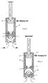
- the metering valve in particular intended for metering flowable, lumpy solid parts, such as jam, yogurt or the like, still consists of a housing 2 containing inflow and outflow channels 9, 10 with a housing in a with respect to the diameter D of Inflow and outflow channels 9, 10 larger diameter, cylindrical cavity 8 of the housing 2 pivotable closing part 1.
- This closing part 1 is designed as the head of a protruding in the housing 2 sealed, with respect to the diameter D1 of the cavity 8 smaller diameter control shaft 3.
- the actual closing surface 6 of the closing part 1 extends parallel to the cylindrical wall 7 of the cavity 8, and the closing part 1 is designed in the form of a cam 5, which is oriented to one side with respect to the pivot axis 4 of the actuating shaft 3.
- the radius R of the closing surface 6 of the cam 5 is dimensioned somewhat smaller than the radius R 'of the cavity 8 outside the region of the cylindrical arrangement plane ZE ' of both openings 9 ' , 10 ' .
- the two inflow and outflow channels 9, 10 are arranged in the housing 2 essentially opposite a pump suction and discharge opening 11.
- the two mutually adjacent openings 9 ' , 10 ' of the inflow and outflow channels 9, 10 spaced apart by an intermediate web 12 are arranged in the cylindrical adjustment plane ZE of the closing surface 6 of the cam 5.
- the closing surface 6 is dimensioned in its arc length L such that the two openings 9 ' , 10 ' are at least closed with a corresponding position of the cam 5 (total closed position according to FIG. 4).
- the maximum possible arc length L extends from one or the other opening edge 11 'of the pump suction and discharge opening 11 to the respective inner opening edge 9''', 10 '''of one or the other opening 9', 10 '(see FIG. 5 ).
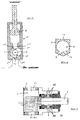
- Drainage channels 9, 10, not as shown in FIGS. 1 to 4 mandatory vertically opposite the suction and discharge opening 11 and must be arranged parallel to each other, which is preferred is, but also, as shown in Fig.6, with appropriate Design of the bottom of the housing can be arranged can.
- the radius R of the closing surface 6 of the cam 5 is dimensioned smaller than the radius R 'of the cavity 8 outside the area of the dosing valve according to the invention, as mentioned above cylindrical arrangement plane ZE 'of the openings 9 ' , 10 'of the two inflow and outflow channels 9, 10, but here in the area outside the arrangement plane ZE', specifically in the middle, the pump suction and discharge opening 11 is arranged.
- both the piston K of the metering pump P and the closing part 1 of the metering valve can be flushed around freely. Due to the given total closability of the metering valve (see FIG.
- an advantageous further development consists in providing on the housing 2 a closable cleaning agent connection 13 leading to the cavity 8. Regardless of whether the detergent is supplied to the top of the pump P through its connection 13 'or vice versa at the bottom of the detergent connection 13 of the metering valve, the pump and metering valve can be rinsed separately and / or sterilized for example when changing the product .
- both the suction and the ejection of the contents of gusset spaces Z or "dead water gussets" advantageously result in free and largely smooth flow-through spaces or flow-through channels in the housing 2, which with regard to, for example, .
- Coarse pieces of fruit are advantageous with regard to the risk of constipation.
- FIG. 7 Only for the sake of completeness is a longitudinal section in FIG. 7 represented by the metering valve, which is also in the present Case consists of two parts, i.e. from the to the drive side completely open housing 2, which on this side by the attachable bearing part LT for the closing part 1 completed becomes.
- the bearing part In the case of sterile operation, the bearing part is LT with connections and channels AK for the passage of a suitable Provide sterile.
Landscapes
- Engineering & Computer Science (AREA)
- Mechanical Engineering (AREA)
- General Engineering & Computer Science (AREA)
- Containers And Packaging Bodies Having A Special Means To Remove Contents (AREA)
- Closures For Containers (AREA)
- Rotary Pumps (AREA)
- Reciprocating Pumps (AREA)
- Devices For Dispensing Beverages (AREA)
Abstract
Description
Die Erfindung betrifft ein Dosierventil an Dosierpumpen gemäß
Oberbegriff des Patentanspruches 1.The invention relates to a metering valve on metering pumps according to
Preamble of
Ein derartiges, insbesondere für die Abdosierung von fließfähigem,
stückige Feststoffteile enthaltendem Dosiergut, wie
Marmelade, Joghurt od.dgl., Dosierventil ist nach der DE-A-195
04 546 C1 bekannt. Dieses bekannte Dosierventil arbeitet
zwar auch wie ein sogenanntes Drehschieberventil (siehe bspw.
US-A-3,228,412), dies aber in der Weise, daß der Nocken, ähnlich
wie ein vor eine Öffnung gehaltener Finger, die Zufuhröffnung
verschließt und dieser zwecks Öffnung geschwenkt
und dabei ein relativ großer Teil des Gehäuseraumes freigestellt
wird, wobei, wie sich gezeigt hat, der in Öffnungsstellung
befindliche Nocken problemlos vom abdosierten Füllgut
ohne Verstopfungsgefahr umströmt werden kann. Die eigentliche
Dosierung erfolgt durch entsprechend getaktete Betätigungsabstimmung
vom Dosierventil und einer über der Öffnung des Zuflußkanals
auf dem Ventilgehäuse angeordnete Dosierpumpe, die
in der DE-A-195 04 546 nicht besonders dargestellt ist. Dieses
Dosierventil arbeitet absolut zufriedenstellend hinsichtlich
der Forderung, bei schwierigem Dosiergut der oben genannten Art
Verstopfungen zu vermeiden und im Gehäuseraum bei Öffnungsstellung
einen großen Durchflußraum zu schaffen.
Nachteilig ist dabei allerdings, daß einer Dosierpumpe zwei
solcher nicht gerade billigen Dosierventile zugeordnet werden
müssen, nämlich eines für den Ansaug- und eines für den Ausstoßvorgang.
Abgesehen vom diesbezüglichen Aufwand, verlangt
die Anordnung zweier solcher Dosierventile zu jeweils einer Dosierpumpe
entsprechenden Raum im Bereich über der Füllstation
bspw. einer sogenannten FFS-Verpackungsmaschine und zudem einen
entsprechenden doppelten Antriebsaufwand für zwei solcher Dosierventile. A metering valve of this type, in particular for metering free-flowing metered solid material containing pieces, such as jam, yoghurt or the like, is known from DE-A-195 04 546 C1. This known metering valve also works like a so-called rotary slide valve (see, for example, US-A-3,228,412), but in such a way that the cam, similar to a finger held in front of an opening, closes the feed opening and pivots it for the purpose of opening and thereby a relatively large part of the housing space is released, whereby, as has been shown, the metered-in filling material can flow around the cam in the open position without any risk of clogging. The actual metering is carried out by correspondingly timed actuation coordination of the metering valve and a metering pump arranged above the opening of the inflow channel on the valve housing, which is not particularly shown in DE-A-195 04 546. This metering valve works absolutely satisfactorily with regard to the requirement to avoid blockages in the case of difficult metered items of the above-mentioned type and to create a large flow space in the housing space when in the open position.
The disadvantage here, however, is that two such metering valves, which are not exactly cheap, must be assigned to a metering pump, namely one for the suction process and one for the exhaust process. Apart from the effort involved, the arrangement of two such metering valves for each metering pump requires space in the area above the filling station, for example a so-called FFS packaging machine, and also a corresponding double drive effort for two such metering valves.
Der Erfindung liegt demgemäß und ausgehend vom Dosierventil der eingangs genannten Art die Aufgabe zugrunde, unter Beibehaltung von dessen Vorteilen einschließlich einfacher Reinigung ein solches Dosierventil dahingehend umzubilden und zu verbessern, daß man für eine Dosierpumpe mit nur einem Dosierventil für den Ansaug- und Ausstoßvorgang auskommt, wobei zudem im Bedarfsfall Ansaug- und Ausströmöffnungen des Dosierventils gleichzeitig verschließbar sein sollen.The invention is accordingly and starting from the metering valve type mentioned the task, while maintaining of its benefits including easy cleaning to redesign and improve such a metering valve, that one for a dosing pump with only one dosing valve for the Suction and exhaust process comes out, and also if necessary Suction and discharge openings of the metering valve at the same time should be lockable.
Diese Aufgabe ist mit einem Dosierventil der eingangs genannten
Art nach der Erfindung durch die im Kennzeichen des Patentanspruches
1 angeführten Merkmale gelöst. Vorteilhafte Weiterbildungen
ergeben sich nach den Unteransprüchen.This task is with a metering valve of the type mentioned
Kind according to the invention by the in the characterizing part of the
Abgesehen davon, daß durch diese erfindungsgemäße Ausbildung des Dosierventiles für eine Dosierpumpe nur ein Ventil erforderlich ist, dessen Schließteil beim Permanentdosierbetrieb nur eine sehr kurze Pendelbewegung zwischen den Öffnungen der Zu- und Abflußkanäle auszuführen hat, kann das Schließteil aufgrund seiner Schließflächenbemessung auch für beide Öffnungen gleichzeitig in Schließstellung gebracht werden, wofür die Minimalbemesssung der Schließfläche ausreicht, wobei die mögliche Maximalbemessung ihre Grenze darin findet, daß beim Ansaugen und Ausstoßen die Durchströmwege zur und von der Ansaug- und Ausstoßöffnung im Gehäuse möglichst optimal durchströmbar sind.Apart from that through this training according to the invention of the dosing valve for a dosing pump only one valve required is, the locking part only in permanent metering operation a very short pendulum movement between the openings of the inlet and Drain channels has to perform, the closing part due its closing surface dimension for both openings at the same time be brought into the closed position, for which the minimum dimension the closing surface is sufficient, the possible Maximum dimensioning finds its limit in that during suction and expelling the flow paths to and from the intake and Ejection opening in the housing can be flowed through as optimally as possible.
Bevorzugt sind die beiden Zu- und Abflußkanäle vertikal und parallel nebeneinander im Gehäuse angeordnet, um möglichst nur schwach gebogene Strömungswege im Ventil von der Saugseite zur Pumpe und von dieser zur Ausstoßöffnung zu erreichen. Schließlich besteht eine vorteilhafte und noch näher zu erläuternde Weiterbildung darin, daß die Flanken des Nockens in Bezug auf die Schwenkachse mit einer konkaven Wölbung versehen sind. The two inflow and outflow channels are preferably vertical and parallel arranged side by side in the housing, if possible only slightly curved flow paths in the valve from the suction side to the Pump and reach from this to the discharge opening. Finally, there is an advantageous one to be explained in more detail Continuing education in that the flanks of the cam are related provide a concave curvature on the swivel axis are.
Wie beim Dosierventil nach der vorerwähnten DE-A-195 04 546 können auch im vorliegenden Fall die dort vorgesehenen scharfen Kanten des Schließteiles zwecks Durchschneiden von bspw. gröberen Fruchtstücken zur Anwendung kommen.As with the metering valve according to the aforementioned DE-A-195 04 546 can also in this case the sharp provided there Edges of the closing part for the purpose of cutting through, for example, coarser ones Pieces of fruit are used.
Das erfindungsgemäße Dosierventil und dessen vorteilhaften Ausführungsformen werden nachfolgend anhand der zeichnerischen Darstellung von Ausführungsbeispielen näher erläutert.The metering valve according to the invention and its advantageous embodiments are subsequently based on the graphic Representation of exemplary embodiments explained in more detail.
Es zeigt
- Fig. 1
- schematisch einen Schnitt durch das Dosierventil in Ansaugstellung;
- Fig. 2
- schematisch einen Schnitt durch das Dosierventil in Ausstoßstellung;
- Fig. 3
- einen entsprechenden Schnitt in Reinigungsstellung des Dosierventiles;
- Fig. 4
- einen Schnitt durch das Dosierventil in totaler Schließstellung;
- Fig. 5
- einen Schnitt durch das Dosierventil mit einer besonderen Ausführungsform des Schließteiles;
- Fig. 6
- im Schnitt eine besondere Ausführungsform des Gehäuses und
- Fig. 7
- einen Längsschnitt durch das Dosierventil ohne aufgesetzter Dosierpumpe.
- Fig. 1
- schematically shows a section through the metering valve in the suction position;
- Fig. 2
- schematically shows a section through the metering valve in the ejection position;
- Fig. 3
- a corresponding section in the cleaning position of the metering valve;
- Fig. 4
- a section through the metering valve in the total closed position;
- Fig. 5
- a section through the metering valve with a special embodiment of the closing part;
- Fig. 6
- on average a special embodiment of the housing and
- Fig. 7
- a longitudinal section through the metering valve without attached metering pump.
Das insbesondere für die Abdosierung von fließfähigem, stückige
Feststoffteile enthaltenden Dosiergut, wie Marmelade, Joghurt
o. dgl. bestimmte Dosierventil besteht nach wie vor aus einem
Zu- und Abflußkanäle 9, 10 enthaltenden Gehäuse 2 mit einem in
einem in bezug auf den Durchmesser D der Zu- und Abflußkanäle
9, 10 durchmessergrößeren, zylindrischen Hohlraum 8 des Gehäuses
2 schwenkbaren Schließteil 1. Dieses Schließteil 1 ist als
Kopf einer in das Gehäuse 2 abgedichtet einragenden, in bezug
auf den Durchmesser D1 des Hohlraumes 8 durchmesserkleineren
Stellwelle 3 ausgebildet. Die eigentliche Schließfläche 6 des
Schließteiles 1 erstreckt sich parallel zur zylindrischen Wand
7 des Hohlraumes 8, und das Schließteil 1 ist in Form eines bezogen
auf die Schwenkachse 4 der Stellwelle 3 von dieser aus
nach einer Seite orientierten Nockens 5 ausgebildet. Der Radius
R der Schließfläche 6 des Nockens 5 ist dabei etwas kleiner als
der Radius R' des Hohlraumes 8 außerhalb des Bereiches der zylindrischen
Anordnungsebene ZE' beider Öffnungen 9',10' bemessen.The metering valve, in particular intended for metering flowable, lumpy solid parts, such as jam, yogurt or the like, still consists of a
Für ein solches Dosierventil ist nun wesentlich, daß die beiden
Zu- und Abflußkanäle 9, 10 im Gehäuse 2 im wesentlichen gegenüber
einer Pumpenansaug- und Ausstoßöffnung 11 angeordnet sind.
Die beiden zueinander benachbarten, durch einen Zwischensteg 12
distanzierten Öffnungen 9', 10' der Zu- und Abflußkanäle 9, 10
sind dabei in der zylindrischen Verstellebene ZE der Schließfläche
6 des Nockens 5 angeordnet. Außerdem ist die Schließfläche
6 in ihrer Bogenlänge L derart bemessen,, daß bei entsprechender
Stellung des Nockens 5 die beiden Öffnungen 9',10' mindestens
verschlossen sind(totale Schließstellung gemäß Fig.4).
Die demgegenüber maximal mögliche Bogenlänge L erstreckt sich
vom einen oder anderen Öffnungsrand 11' der Pumpenansaug- und
Ausstoßöffnung 11 zum jeweils inneren Öffnungsrand 9''',10'''
der einen oder anderen Öffnung 9',10' (siehe hierzu Fig.5).For such a metering valve it is now essential that the two inflow and
"Im wesentlichen gegenüber" ist dabei so zu verstehen, daß die
Abflußkanäle 9, 10, nicht wie in den Fig. 1 bis 4 dargestellt,
zwingend vertikal gegenüber der Ansaug- und Ausstoßöffnung 11
und parallel zueinander angeordnet sein müssen, was jedoch bevorzugt
wird, sondern auch, wie in Fig.6 dargestellt, bei entsprechender
Gestaltung der Gehäuseunterseite angeordnet sein
können."Essentially opposite" is to be understood to mean that the
Mit Rücksicht auf die in den Fig. 1 bis 4 mit angegebenen Funktionsbeschriftungen
und Stellungen der beteiligten Elemente,
einschließlich der hier mit dargestellten Dosierpumpe P, ist
eine Funktionsbeschreibung entbehrlich. Gleiches gilt auch für
die Betätigungs- bzw. Antriebselemente für den Kolben K der Dosierpumpe
P und das Schließteil 1 des Dosierventiles, zumal für
die Bewegungen entsprechende Pfeile angegeben sind.With regard to the function labels given in FIGS. 1 to 4
and positions of the elements involved,
including the metering pump P shown here
a functional description can be dispensed with. The same applies to
the actuation or drive elements for the piston K of the metering pump
P and the
Aus Gründen der erforderlichen Reinigung bei Produktwechsel und
dieserhalb unter Bezug auf Fig. 3 ist auch bei dieser erfindungsgemäßen
Ausbildung des Dosierventils, wie vorerwähnt, der
Radius R der Schließfläche 6 des Nockens 5 kleiner bemessen als
der Radius R' des Hohlraumes 8 außerhalb des Bereiches der zylindrischen
Anordnungsebene ZE' der Öffnungen 9',10' der beiden
Zu- und Abflußkanäle 9, 10 , wobei aber hier im Bereich außerhalb
der Anordnungsebene ZE', und zwar mittig, die Pumpenansaug- und Ausstoßöffnung 11 angeordnet ist. Wie aus Fig.3 ersichtlich,
ist dabei sowohl der Kolben K der Dosierpumpe P als
auch das Schließteil 1 des Dosierventiles frei umspülbar.
Aufgrund der gegebenen, totalen Schließbarkeit des Dosierventiles
(siehe Fig.4) besteht eine vorteilhafte Weiterbildung
darin, am Gehäuse 2 einen zum Hohlraum 8 führenden, verschließbaren
Reinigungsmittelanschluß 13 vorzusehen. Egal ob nun das
Reinigungsmittel oben an der Pumpe P durch deren Anschluß 13'
oder umgekehrt unten am Reinigungsmittelanschluß 13 des Dosierventiles
zugeleitet wird, auf jeden Fall können dadurch Pumpe
und Dosierventil bspw. bei Produktwechsel für sich separat
freigespült und/oder bspw. auch sterilisiert werden. For reasons of the necessary cleaning when changing the product and for this reason with reference to FIG. 3, the radius R of the
Was die vorerwähnte Weiterbildung betrifft, gemäß der die Flanken
5' des Nackens 5 in Bezug auf die Schwenkachse 4 mit einer
konkaven Wölbung 5'' versehen sind, so wird diesbezüglich auf
die Fig.5 verwiesen. Bei einer derartigen Ausbildung ergeben
sich vorteilhaft sowohl beim Ansaugen als auch Ausstoßen des
Füllgutes von Zwickelräumen Z bzw. "Totwasserzwickeln" (siehe
vergleichsweise Fig.1,2) freie und strömungsmäßig weitgehend
glatte Durchströmräume bzw. Durchströmkanäle im Gehäuse 2, was
mit Rücksicht auf bspw. grobe Fruchtstücke hinsichtlich einer
Verstopfungsgefahr vorteilhaft ist.As regards the aforementioned development, according to which the
Nur der Vollständigkeit halber ist in Fig. 7 ein Längsschnitt
durch das Dosierventil dargestellt, das auch im vorliegenden
Fall aus zwei Teilen besteht, d.h. aus dem zur Antriebsseite
hin völlig offenen Gehäuse 2, das nach dieser Seite durch das
ansetzbare Lagerteil LT für das Schließteil 1 abgeschlossen
wird. Für den Fall steriler Betriebsweise ist das Lagerteil LT
mit Anschlüssen und Kanälen AK für die Durchleitung eines geeigneten
Sterilmittels versehen.Only for the sake of completeness is a longitudinal section in FIG. 7
represented by the metering valve, which is also in the present
Case consists of two parts, i.e. from the to the drive side
completely open
Claims (4)
dadurch gekennzeichnet,
daß die beiden Zu- und Abflußkanäle (9, 10) im Gehäuse (2) im wesentlichen gegenüber einer Pumpenansaug- und Ausstoßöffnung (11) und die durch einen Zwischensteg (12) distanzierten Öffnungen (9',10') der Zu- und Abflußkanäle (9, 10) in der zylindrischen Verstellebene (ZE) der Schließfläche (6) des Nockens (5) angeordnet sind, wobei der Radius (R) der Schließfläche (6) des Nockens (5) kleiner ist als der Radius (R') des Hohlraumes (8) außerhalb des Bereiches der zylindrischen Anordnungsebene (ZE') beider Öffnungen (9',10'), und daß die Schließfläche (6) in ihrer Bogenlänge (L) derart bemessen ist, daß bei entsprechender Stellung des Nockens (5) mindestens die beiden Öffnungen (9',10') verschlossen sind oder maximal die Bogenlänge (L) sich vom einen oder anderen Öffnungsrand (11') der Pumpenansaug- und Ausstoßöffnung (11) zum jeweils inneren Öffnungsrand (9''',10''') der einen oder anderen Öffnung (9',10') erstreckt.Dosing valve on dosing pumps, in particular for the dosing of flowable, dense solid-containing dosing material, such as jam, yogurt or the like, consisting of a housing (2) containing inflow and outflow channels (9, 10) with a in one with respect to the Diameter (D) of the inflow and outflow channels (9, 10) larger diameter, cylindrical cavity (8) of the housing (2) pivotable closing part (1), which is designed as the head of an actuating shaft (3) projecting in the housing (2) and its closing surface (6) extends parallel to the cylindrical wall (7) of the cavity (8), the closing part (1) in the form of a cam oriented towards one side with respect to the pivot axis (4) of the adjusting shaft (3) (5) and the radius (R) of the closing surface (6) of the cam (5) is smaller than the radius (R ' ) of the cavity (8) outside the area of the cylindrical arrangement plane (ZE ' ) of both openings (9 ' , 10th ' ),
characterized,
that the two inflow and outflow channels (9, 10) in the housing (2) essentially opposite a pump suction and discharge opening (11) and the openings (9 ' , 10 ' ) of the inflow and outflow channels spaced apart by an intermediate web (12) (9, 10) are arranged in the cylindrical adjustment plane (ZE) of the closing surface (6) of the cam (5), the radius (R) of the closing surface (6) of the cam (5) being smaller than the radius (R ' ) of the cavity (8) outside the area of the cylindrical arrangement plane (ZE ' ) of both openings (9 ' , 10 ' ), and that the closing surface (6) is dimensioned in its arc length (L) in such a way that when the cam (5 ) at least the two openings (9 ', 10') are closed or at most the arc length (L) extends from one or the other opening edge (11 ') of the pump suction and discharge opening (11) to the respective inner opening edge (9''', 10 ''') of one or the other opening (9', 10 ').
dadurch gekennzeichnet,
daß die Zu- und Abflußkanäle (9, 10) vertikal und parallel nebeneinander im Gehäuse (2) angeordnet sind.Dosing valve according to claim 1,
characterized,
that the inlet and outlet channels (9, 10) are arranged vertically and parallel next to each other in the housing (2).
dadurch gekennzeichnet,
daß die Flanken (5') des Nockens (5) in Bezug auf die Schwenkachse (4) mit einer konkaven Wölbung (5'') versehen sind.Dosing valve according to claim 2,
characterized,
that the flanks (5 ' ) of the cam (5) are provided with a concave curvature (5'') with respect to the pivot axis (4).
dadurch gekennzeichnet,
daß am Gehäuse (2) ein zum Hohlraum (8) führender Reinigungsmittelanschluß (13) angeordnet ist.Dosing valve according to one of claims 1 to 3,
characterized,
that a cleaning agent connection (13) leading to the cavity (8) is arranged on the housing (2).
Applications Claiming Priority (2)
| Application Number | Priority Date | Filing Date | Title |
|---|---|---|---|
| DE19822430A DE19822430C1 (en) | 1998-05-19 | 1998-05-19 | Dosing valve on dosing pumps |
| DE19822430 | 1998-05-19 |
Publications (3)
| Publication Number | Publication Date |
|---|---|
| EP0959005A2 true EP0959005A2 (en) | 1999-11-24 |
| EP0959005A3 EP0959005A3 (en) | 2000-10-25 |
| EP0959005B1 EP0959005B1 (en) | 2004-03-17 |
Family
ID=7868282
Family Applications (1)
| Application Number | Title | Priority Date | Filing Date |
|---|---|---|---|
| EP99109419A Expired - Lifetime EP0959005B1 (en) | 1998-05-19 | 1999-05-11 | Metering valve |
Country Status (3)
| Country | Link |
|---|---|
| US (1) | US6179587B1 (en) |
| EP (1) | EP0959005B1 (en) |
| DE (1) | DE19822430C1 (en) |
Cited By (3)
| Publication number | Priority date | Publication date | Assignee | Title |
|---|---|---|---|---|
| WO2000068078A1 (en) * | 1999-05-11 | 2000-11-16 | Peter Owen Davies | Apparatus for metering fluids |
| WO2002031357A3 (en) * | 2000-10-10 | 2002-09-06 | Beckman Coulter Inc | Fluid-moving device with integrated valve |
| WO2016059551A3 (en) * | 2014-10-13 | 2016-06-09 | Alfa S.R.L. | Positive-displacement pump and pumping group for fluid products and method for the use thereof |
Families Citing this family (8)
| Publication number | Priority date | Publication date | Assignee | Title |
|---|---|---|---|---|
| RU2180708C1 (en) * | 2000-08-18 | 2002-03-20 | Открытое акционерное общество "Машиностроительный завод "АРСЕНАЛ" | Pump for thick viscous slurry |
| GB0201103D0 (en) * | 2002-01-18 | 2002-03-06 | Mount Packaging Systems Ltd | Liquid dispensing pump |
| CA2519196A1 (en) * | 2003-03-27 | 2004-10-14 | Swf Companies, Inc. | High-speed continuous action form-fill-seal apparatus |
| KR100996576B1 (en) * | 2003-05-09 | 2010-11-24 | 주식회사 탑 엔지니어링 | Liquid crystal dropping device and liquid crystal dropping method |
| CN101144466B (en) * | 2007-11-15 | 2010-04-21 | 齐玉符 | Differential constant flow pump |
| KR20120082989A (en) * | 2011-01-17 | 2012-07-25 | 삼성전자주식회사 | Washing machine |
| FR3006407B1 (en) * | 2013-06-04 | 2015-07-17 | Capsum | BOOSTER VALVE, FLUID ASSAY DEVICE AND ASSAY METHOD THEREOF |
| CN105020130A (en) * | 2015-08-02 | 2015-11-04 | 黄锦成 | Three-way metering ball valve of metering pump |
Citations (2)
| Publication number | Priority date | Publication date | Assignee | Title |
|---|---|---|---|---|
| US3228412A (en) | 1962-07-16 | 1966-01-11 | Bartelt Engineering Co Inc | Dispensing valve having particular cleaning means |
| DE19504546C1 (en) | 1995-02-11 | 1996-08-01 | Hassia Verpackung Ag | Dosing valve on pump, esp. for fluids with suspended solids, e.g. pieces of fruit in jam or yoghurt |
Family Cites Families (5)
| Publication number | Priority date | Publication date | Assignee | Title |
|---|---|---|---|---|
| US2827207A (en) * | 1954-05-04 | 1958-03-18 | Robert R Sprole | Fluid measuring mechanism for filling machines |
| US3266435A (en) * | 1963-12-09 | 1966-08-16 | Smith Eugene | Pump for semi-fluid material |
| DE6941284U (en) * | 1969-10-23 | 1970-02-19 | Huennebeck Gmbh | PUMP FOR TRANSFERRING LIQUID SUBSTANCES |
| US4457348A (en) * | 1982-07-07 | 1984-07-03 | Mueller Martin J | Food product fill pump |
| FR2671398B1 (en) * | 1991-01-03 | 1995-09-08 | Atelier Etudes Realisa Automat | DEVICE FOR DOSING AND DISPENSING A PASTY MATERIAL. |
-
1998
- 1998-05-19 DE DE19822430A patent/DE19822430C1/en not_active Expired - Fee Related
-
1999
- 1999-05-11 EP EP99109419A patent/EP0959005B1/en not_active Expired - Lifetime
- 1999-05-18 US US09/313,399 patent/US6179587B1/en not_active Expired - Fee Related
Patent Citations (2)
| Publication number | Priority date | Publication date | Assignee | Title |
|---|---|---|---|---|
| US3228412A (en) | 1962-07-16 | 1966-01-11 | Bartelt Engineering Co Inc | Dispensing valve having particular cleaning means |
| DE19504546C1 (en) | 1995-02-11 | 1996-08-01 | Hassia Verpackung Ag | Dosing valve on pump, esp. for fluids with suspended solids, e.g. pieces of fruit in jam or yoghurt |
Cited By (6)
| Publication number | Priority date | Publication date | Assignee | Title |
|---|---|---|---|---|
| WO2000068078A1 (en) * | 1999-05-11 | 2000-11-16 | Peter Owen Davies | Apparatus for metering fluids |
| WO2002031357A3 (en) * | 2000-10-10 | 2002-09-06 | Beckman Coulter Inc | Fluid-moving device with integrated valve |
| US6520755B1 (en) | 2000-10-10 | 2003-02-18 | Beckman Coulter, Inc. | Fluid-moving device with integrated valve |
| WO2016059551A3 (en) * | 2014-10-13 | 2016-06-09 | Alfa S.R.L. | Positive-displacement pump and pumping group for fluid products and method for the use thereof |
| AU2015332105B2 (en) * | 2014-10-13 | 2019-06-20 | Alfa S.R.L. | Positive-displacement pump and pumping group for fluid products and method for the use thereof |
| US11053930B2 (en) | 2014-10-13 | 2021-07-06 | Alfa S. R. L. | Positive-displacement pump and pumping group for fluid products and method for the use thereof |
Also Published As
| Publication number | Publication date |
|---|---|
| DE19822430C1 (en) | 2000-02-10 |
| EP0959005B1 (en) | 2004-03-17 |
| EP0959005A3 (en) | 2000-10-25 |
| US6179587B1 (en) | 2001-01-30 |
Similar Documents
| Publication | Publication Date | Title |
|---|---|---|
| EP3765180B1 (en) | Mixing device having a two-part closure lid | |
| DE10110888A1 (en) | Dosing pump and dispenser for fluid or pasty substances has two storage chambers side-by-side with separate dosing pumps worked by rocker arrangement | |
| DE10359779A1 (en) | Filling element and filling machine with such filling elements | |
| EP0959005B1 (en) | Metering valve | |
| DE3707779A1 (en) | DEVICE FOR PRODUCING ICE CREAM, MILK SHAKE OR FROZEN SAUCE FOOD FROM A FLOWABLE APPROACH | |
| DE29909542U1 (en) | Filling valve for filling flat bag packaging in particular | |
| EP3765183B1 (en) | Device for converting a linear movement in a stationary system into a rotational movement about a pivot axis in a system which rotates about a rotational axis | |
| EP0265597A2 (en) | Apparatus for the dosed filling of containers with liquid or viscous material | |
| DE19537303B4 (en) | Device for homogenizing flowable substances | |
| DE102008022398A1 (en) | Filling element and filling machine with such filling elements | |
| EP0540944B1 (en) | Metering pump for viscous products | |
| DE3204611A1 (en) | FILLING MACHINE | |
| DE2233335A1 (en) | LOCKING MECHANISM ON A DRAIN PIPE IN SAE MACHINES | |
| EP1527678A1 (en) | Mixer | |
| DE3206141A1 (en) | Control valve for a dosing device for dosing liquid media, in particular foods | |
| DE19504546C1 (en) | Dosing valve on pump, esp. for fluids with suspended solids, e.g. pieces of fruit in jam or yoghurt | |
| DE69504044T2 (en) | SELF-CLOSING DISPENSER | |
| DE19960221C2 (en) | Cell wheel lock with improved sealing against leakage air | |
| DE69624074T2 (en) | liquid flow path | |
| DE68917868T2 (en) | Dispensing - Device and Procedure. | |
| DE666373C (en) | Spout with measuring device for bottles etc. | |
| EP2112122A2 (en) | Container | |
| DE2303736C3 (en) | Flow control device for a pneumatic conveyor trough | |
| DE10218164B4 (en) | Dosing and filling system, especially for pasty foods | |
| DE2038010A1 (en) | Sausage meat filler |
Legal Events
| Date | Code | Title | Description |
|---|---|---|---|
| PUAI | Public reference made under article 153(3) epc to a published international application that has entered the european phase |
Free format text: ORIGINAL CODE: 0009012 |
|
| AK | Designated contracting states |
Kind code of ref document: A2 Designated state(s): FR GB IT |
|
| AX | Request for extension of the european patent |
Free format text: AL;LT;LV;MK;RO;SI |
|
| PUAL | Search report despatched |
Free format text: ORIGINAL CODE: 0009013 |
|
| AK | Designated contracting states |
Kind code of ref document: A3 Designated state(s): AT BE CH CY DE DK ES FI FR GB GR IE IT LI LU MC NL PT SE |
|
| AX | Request for extension of the european patent |
Free format text: AL;LT;LV;MK;RO;SI |
|
| RIC1 | Information provided on ipc code assigned before grant |
Free format text: 7B 65B 39/00 A, 7F 04B 7/00 B, 7F 04B 13/00 B |
|
| 17P | Request for examination filed |
Effective date: 20010217 |
|
| AKX | Designation fees paid |
Free format text: FR GB IT |
|
| GRAP | Despatch of communication of intention to grant a patent |
Free format text: ORIGINAL CODE: EPIDOSNIGR1 |
|
| GRAS | Grant fee paid |
Free format text: ORIGINAL CODE: EPIDOSNIGR3 |
|
| GRAA | (expected) grant |
Free format text: ORIGINAL CODE: 0009210 |
|
| AK | Designated contracting states |
Kind code of ref document: B1 Designated state(s): FR GB IT |
|
| PG25 | Lapsed in a contracting state [announced via postgrant information from national office to epo] |
Ref country code: IT Free format text: LAPSE BECAUSE OF FAILURE TO SUBMIT A TRANSLATION OF THE DESCRIPTION OR TO PAY THE FEE WITHIN THE PRE;WARNING: LAPSES OF ITALIAN PATENTS WITH EFFECTIVE DATE BEFORE 2007 MAY HAVE OCCURRED AT ANY TIME BEFORE 2007. THE CORRECT EFFECTIVE DATE MAY BE DIFFERENT FROM THE ONE RECORDED.SCRIBED TIME-LIMIT Effective date: 20040317 |
|
| REG | Reference to a national code |
Ref country code: GB Ref legal event code: FG4D Free format text: NOT ENGLISH |
|
| GBT | Gb: translation of ep patent filed (gb section 77(6)(a)/1977) |
Effective date: 20040317 |
|
| PG25 | Lapsed in a contracting state [announced via postgrant information from national office to epo] |
Ref country code: GB Free format text: LAPSE BECAUSE OF NON-PAYMENT OF DUE FEES Effective date: 20040617 |
|
| ET | Fr: translation filed | ||
| PLBE | No opposition filed within time limit |
Free format text: ORIGINAL CODE: 0009261 |
|
| STAA | Information on the status of an ep patent application or granted ep patent |
Free format text: STATUS: NO OPPOSITION FILED WITHIN TIME LIMIT |
|
| PG25 | Lapsed in a contracting state [announced via postgrant information from national office to epo] |
Ref country code: FR Free format text: LAPSE BECAUSE OF NON-PAYMENT OF DUE FEES Effective date: 20050131 |
|
| GBPC | Gb: european patent ceased through non-payment of renewal fee |
Effective date: 20040617 |
|
| REG | Reference to a national code |
Ref country code: FR Ref legal event code: ST |
|
| 26N | No opposition filed |
Effective date: 20041220 |