EP0958623B1 - Einspurige trockenzellenpatrone oder gehäuse - Google Patents
Einspurige trockenzellenpatrone oder gehäuse Download PDFInfo
- Publication number
- EP0958623B1 EP0958623B1 EP97948651A EP97948651A EP0958623B1 EP 0958623 B1 EP0958623 B1 EP 0958623B1 EP 97948651 A EP97948651 A EP 97948651A EP 97948651 A EP97948651 A EP 97948651A EP 0958623 B1 EP0958623 B1 EP 0958623B1
- Authority
- EP
- European Patent Office
- Prior art keywords
- housing
- dry cell
- wall
- housing according
- appliance
- Prior art date
- Legal status (The legal status is an assumption and is not a legal conclusion. Google has not performed a legal analysis and makes no representation as to the accuracy of the status listed.)
- Expired - Lifetime
Links
- 238000010276 construction Methods 0.000 claims description 11
- 238000003780 insertion Methods 0.000 claims description 7
- 230000037431 insertion Effects 0.000 claims description 7
- 210000004027 cell Anatomy 0.000 description 124
- 238000000034 method Methods 0.000 description 4
- 230000008901 benefit Effects 0.000 description 3
- 238000009434 installation Methods 0.000 description 2
- 230000003993 interaction Effects 0.000 description 2
- 239000000463 material Substances 0.000 description 2
- 238000012986 modification Methods 0.000 description 2
- 230000004048 modification Effects 0.000 description 2
- 102100026827 Protein associated with UVRAG as autophagy enhancer Human genes 0.000 description 1
- 101710102978 Protein associated with UVRAG as autophagy enhancer Proteins 0.000 description 1
- 239000000853 adhesive Substances 0.000 description 1
- 230000001070 adhesive effect Effects 0.000 description 1
- 230000000747 cardiac effect Effects 0.000 description 1
- 210000002421 cell wall Anatomy 0.000 description 1
- 230000008859 change Effects 0.000 description 1
- 230000006735 deficit Effects 0.000 description 1
- 238000010586 diagram Methods 0.000 description 1
- 230000001771 impaired effect Effects 0.000 description 1
- 230000002452 interceptive effect Effects 0.000 description 1
- 239000002184 metal Substances 0.000 description 1
- 230000002028 premature Effects 0.000 description 1
- 230000008569 process Effects 0.000 description 1
- 210000001364 upper extremity Anatomy 0.000 description 1
Images


Classifications
-
- H—ELECTRICITY
- H01—ELECTRIC ELEMENTS
- H01M—PROCESSES OR MEANS, e.g. BATTERIES, FOR THE DIRECT CONVERSION OF CHEMICAL ENERGY INTO ELECTRICAL ENERGY
- H01M50/00—Constructional details or processes of manufacture of the non-active parts of electrochemical cells other than fuel cells, e.g. hybrid cells
- H01M50/20—Mountings; Secondary casings or frames; Racks, modules or packs; Suspension devices; Shock absorbers; Transport or carrying devices; Holders
- H01M50/204—Racks, modules or packs for multiple batteries or multiple cells
- H01M50/207—Racks, modules or packs for multiple batteries or multiple cells characterised by their shape
- H01M50/213—Racks, modules or packs for multiple batteries or multiple cells characterised by their shape adapted for cells having curved cross-section, e.g. round or elliptic
-
- H—ELECTRICITY
- H01—ELECTRIC ELEMENTS
- H01M—PROCESSES OR MEANS, e.g. BATTERIES, FOR THE DIRECT CONVERSION OF CHEMICAL ENERGY INTO ELECTRICAL ENERGY
- H01M50/00—Constructional details or processes of manufacture of the non-active parts of electrochemical cells other than fuel cells, e.g. hybrid cells
- H01M50/50—Current conducting connections for cells or batteries
- H01M50/572—Means for preventing undesired use or discharge
- H01M50/584—Means for preventing undesired use or discharge for preventing incorrect connections inside or outside the batteries
- H01M50/59—Means for preventing undesired use or discharge for preventing incorrect connections inside or outside the batteries characterised by the protection means
- H01M50/597—Protection against reversal of polarity
-
- H—ELECTRICITY
- H01—ELECTRIC ELEMENTS
- H01M—PROCESSES OR MEANS, e.g. BATTERIES, FOR THE DIRECT CONVERSION OF CHEMICAL ENERGY INTO ELECTRICAL ENERGY
- H01M2200/00—Safety devices for primary or secondary batteries
- H01M2200/30—Preventing polarity reversal
-
- Y—GENERAL TAGGING OF NEW TECHNOLOGICAL DEVELOPMENTS; GENERAL TAGGING OF CROSS-SECTIONAL TECHNOLOGIES SPANNING OVER SEVERAL SECTIONS OF THE IPC; TECHNICAL SUBJECTS COVERED BY FORMER USPC CROSS-REFERENCE ART COLLECTIONS [XRACs] AND DIGESTS
- Y02—TECHNOLOGIES OR APPLICATIONS FOR MITIGATION OR ADAPTATION AGAINST CLIMATE CHANGE
- Y02E—REDUCTION OF GREENHOUSE GAS [GHG] EMISSIONS, RELATED TO ENERGY GENERATION, TRANSMISSION OR DISTRIBUTION
- Y02E60/00—Enabling technologies; Technologies with a potential or indirect contribution to GHG emissions mitigation
- Y02E60/10—Energy storage using batteries
Definitions
- the present invention relates to cartridges or housings which receive dry cells in an in-line orientation and are subsequently inserted into appliances, such as flashlights, which utilise those dry cells.
- Generally dry cell powered appliances have cavities which receive dry cells. These cavities have covers associated with them and the covers may generally have a sticker adhered to them which indicates the orientation in which the dry cells should be positioned. Alternatively the cavities or the covers are embossed to indicate the orientation.
- the orientation that dry cells are ultimately installed in is dictated by the person installing the dry cells, and because they generally do not check the correct orientation from the diagram provided, the process will generally rely on that person remembering the correct orientation. The difficulty with this is, that if dry cells are placed in the wrong orientation then there is a chance that some dry cells will be dissipated or may become incapable of providing current. This could occur even while an appliance is switched off. Also the appliance may have polarity sensitive circuits which might be damaged by incorrect polarity.
- US-A-4,595,641 discloses an integral battery compartment in portable electronic equipment, such as a cardiac pacer system analyzer, comprising means for ensuring correct orientation of cells connected in series. It is an object of the present invention to provide a housing or cartridge which ameliorates, at least in part at least one of the disadvantages of the prior art.
- the invention provides a housing having a generally elongate body to hold at least two dry cells together in series connection in an end to end or in-line orientation, and including: a first end having a first end wall which will receive a positive terminal of a dry cell and a second end having a second end wall; two or more dry cell cavities which each have at least one side wall and further having an intermediate wall common to adjacent cavities, the or each intermediate wall cooperating with a contact member which electrically connects the positive terminal of one dry cell with the negative terminal of an adjacent dry cell when dry cells are placed in correct orientation in adjacent cavities; said intermediate walls having or including a portion having a predetermined thickness and an axial passage therethrough, said thickness being less than the length of a raised cylindrical positive terminal of a dry cell, said intermediate walls having a first surface facing in the direction of said second end and a second surface facing in the direction of said first end; the or each said intermediate wall and said contact member being arranged so that a side of said contact member facing said second end is recessed relative to said first surface, so that
- said passage through said second end wall cooperates with the surface of a negative terminal of a dry cell in the cavity at said second end, so that when correctly positioned in said cavity, the surface of said negative terminal is recessed from the outwardly facing surface of said second end wall.
- the thickness of said second end wall and a portion of said intermediate wall or said intermediate wall determines the depth of recessing.
- said intermediate walls are each constructed from two wall parts with a space between each wall part to receive said contact member, so that a surface or a portion of a surface of said contact member is recessed from said first surface by the thickness of said wall part which includes said first surface.
- said contact member is held in each intermediate wall by the joining of each wall part together at one end, to enclose the space between the wall parts.
- said housing has a generally semi-cylindrical body in which said dry cell cavities are formed.
- said holding members are extensions of said body which partially enclose a volume to form and occlude said cavities.
- said body includes an aperture to provide some resilient flexibility to assist said holding members to move, to allow placement and removal of said dry cells.
- said contact members include a bias means associated with the contact member to engage a negative terminal of a dry cell.
- said aperture has the profile similar to the silhouette of a dry cell with a representation of a positive terminal being visible.
- the contact member includes at least one angled barb which engages one of the facing wall parts of said end wall, said barb being angled to prevent removal of the contact member once it has been positioned in the end wall.
- said passage through said end intermediate wall and said first and second end walls is of a generally U-shaped, or semi circular or part semi circular construction.
- said first end wall is semi-circular.
- said intermediate walls have a generally circular periphery.
- said passage through intermediate walls is of a substantially U-shaped construction.
- said intermediate wall is made from a single wall part and has said contact member attached to said second surface, so as to recess said contact member from said first surface.
- the housing includes holding members cooperating with said side walls, said holding members being moveable to allow insertion or removal of a dry cell into or out of said cavities
- the invention also provides an appliance powered by dry cells which are serially connected and mounted in a housing as described in any one of the above paragraphs, wherein the positive terminal of said appliance is constructed so that it has at least one projection associated with it which can engage an external surface of said second end wall of said housing as described in any one of the above paragraphs, so as to prevent said positive terminal of said appliance making contact with the negative terminal of a dry cell in a cavity associated with the second end wall of said housing.
- said at least one projection also engages an external surface of said first end wall so as to prevent said positive terminal of said appliance making contact with the negative terminal of an incorrectly positioned dry cell in a dry cell cavity associated with said first end wall of said housing.
- the invention further provides a housing as described above, with said cavities including a body portion having at least one side wall portion , said housing including a part of said body associated with each cavity having a shaped aperture therethrough which has a profile similar to a silhouette of a dry cell with a part of the aperture representing the positive end of a dry cell, said part of said aperture and said aperture being oriented so as to correspond to and indicate the correct orientation of the dry cell in said cavity, said aperture being of a size which will prevent said dry cell passing through said aperture.
- said housing is generally cylindrical.
- said shaped aperture cooperates with said holding means to assist said holding means to be moveable to allow removal or insertion of said dry cells out of or into said cavity.
- said housing includes a holding means to releaseably hold said dry cells in said cavity.
- said aperture assists in the removal of a dry cell from said cavity.
- the invention also provides an appliance in combination with a housing as described in any one of the above paragraphs, wherein said appliance has a housing receiving cavity to receive said housing, said appliance including a positive and negative terminal for electrical connection to first and second ends of said housing, said housing including intermediate walls having a thickness or depth of a dimension so that the overall length of said housing is greater than the length of the same number of said dry cells, which said housing is meant to receive, when said same number of dry cells are series connected from end to end, said housing receiving cavity being of a dimension such that if said number of dry cells are placed in said housing receiving cavity without said housing, the positive and negative terminal of said appliance are sufficiently spaced that no simultaneous electrical connection can be made between all of said dry cells and said positive and negative terminals.
- Embodiments of the invention for the housing have features which ensure that dry cells inserted in an incorrect orientation in the cavity will have the negative end of the dry cell not in contact with the contact member between adjacent cavities. Thus any impairment of the dry cell to perform as required will not occur.
- the presence of a shaped aperture to indicate the orientation of the dry cell in the cavity provides several advantages namely: a more reliable method of identification in low light situations; a means to reduce the amount of force required to open the holding members; and a means to simultaneously reduce the amount of plastic in the housing or cartridge.
- an appliance having the features discussed above in paragraphs 19 to 21 has a relatively simple means to protect the circuits of the appliance, to prevent the incorrect installation into the appliance of a housing containing dry cells in correct orientation in the housing.
- the appliance and housing in combination prevent the appliance being used without the housing thereby forcing a user to install all dry cells in the correct orientation by having to use the housing, otherwise no operation of the appliance will occur, without interfering with the dry cell arrangement.
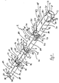
- FIG. 1 Illustrated in Figure 1 is a housing 2 which includes a body portion 4.
- the housing 2 is meant to receive four dry cells in an in-line or end to end orientation, so that when they are correctly installed they are connected in series.
- the body portion 4 illustrated in Fig I has a generally semi-cylindrical shape because this embodiment is required to be inserted into a cylindrical cavity in an appliance.
- the shape of the body 4 can be manufactured to conform to any shape as desired to be received by a matching cavity in an appliance. For example the shape could be square or triangular.
- Body 4 has three intermediate walls 6 and first and second end walls 8 and 10, respectively. The walls 6, 8 and 10 together with the body 4 form dry cell cavities 62, 64, 66 and 68.
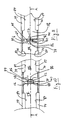
- each of the dry cell cavities 62, 64, 66, 68 has a generally rectangular aperture 70 which is best illustrated in Figures 5, 4 and 2.
- the aperture 70 has a profile which is similar to a silhouette of a dry cell.
- the aperture 70 in keeping with the silhouette of a dry cell, has a three sided portion 72 which represents the raised cylindrical positive terminal of a dry cell. This portion 72 indicates to a user which direction the positive end and positive terminal of a dry cell has to be inserted into a cavity 62, 64, 66, 68.
- One advantage of the aperture 70 is that if there is any light present, even though that light may not be enough to read by, a user peering through the aperture 70, will be able to determine which direction is correct for the proper installation of a dry cell.
- each aperture 70 has a fourth function which will be described later.
- the first end wall 8 is at a first end of the housing 2 and is of a generally semi-annular construction with a semi-circular periphery and a semi circular cut-out portion 12 which is positioned so as to receive and locate a centrally mounted raised cylindrical positive terminal of a cylindrical dry cell when such a dry cell is located in cavity 68.
- the thickness 14 of the first end wall 8 is such that when the circular rim of a dry cell contacts the inner surface 16 of the first end wall 8, the raised cylindrical positive terminal of the dry cell will project past the outwardly facing surface 18 of the wall 8.
- the second end wall 10 is located at a second end of the housing 2 and has a generally circular periphery, but has a generally U-shaped form, whereby the "U" defines a straight sided half round periphery of a passage 20, through the central portions of the second end wall.
- the second end wall 10 if a dry cell is correctly inserted into the cavity 62, will be next adjacent the negative terminal of that dry cell.
- the second end wall 10 has a thickness 22 which will effectively recess any negative terminal of a dry cell (which contacts the inner surface 24), from the outer surface 26 of the second end wall 10. The depth of the recess will be to the depth of the thickness 22 of wall 10.
- the U-shaped passage 20 is of sufficient width to serve the purpose of preventing a dry cell placed in the adjacent cavity 62 from exiting the cavity 62 axially, as well as being of sufficient width so that a biased negative terminal of an appliance, in which the housing 2 will be installed, can make contact with the negative terminal of a dry cell placed in the cavity 62.
- the intermediate wall 6 will now be described with reference to Figs 1, 3, 7, 9 and 14. Because of congestion most of the reference numbers below are only illustrated in regards to the intermediate wall 6, which is closest to first end wall 8.
- the intermediate wall 6 is constructed from two wall parts 28 and 30 which are positioned so as to provide a space 32 between them. Into the space 32 is inserted a contact member 34.
- the wall parts 28 and 30 have a generally circular periphery and are of a generally U-shaped construction with a passage 36 through them.
- the passage 36 is defined by the half rounded straight sided generally U-Shaped inner periphery of the wall parts 28 and 30.
- the contact member 34 is also positioned inside the passage 36.
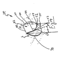
- the contact member 34 has a generally circular and planar first portion 38 which when it is installed between wall parts 28 and 30 remains recessed relative to the first surface 40 of the wall part 28. It remains recessed because the first portion 38 of the contact member 34 is held by the wall parts 28 and 30 in position at the top and bottom and side portions of the contact member 34 and the first portion 38 cannot protrude through.
- the only part of the contact member 34 not sandwiched by the wall parts 28 and 30 are those portions of the contact member 34 which are exposed in the passage 36.
- the portions of contact member 34 exposed in the passage 36 include second portion 42 having a first part 44 which is at an angle to the first portion 38 (before a dry cell is installed).
- the first part 44 is of a generally rectangular and planar construction and is effectively hinged and biased relative to the first portion 38 by a bend line 48. Because the first part 44 is formed at an angle to the first portion 38, the first part 44 will provide some bias against movement towards the first portion 38.
- the second portion 42 also includes a second part 46 which is formed at an angle to the first part 44.
- the second part 46 is joined to the first part 44 at a bend line 50.
- the second part 46 is of a generally planar and semi-circular construction of a diameter which is equal to the width of the rectangular first part 44.
- Extending away from a mid-section of the second part 46 is a tab portion 52.
- the tab portion 52 is of a generally rectangular and planar construction and is best illustrated in Fig 14.
- the tab portion 52 is formed at an angle to the second part 46 and is joined to the circumferential portion of the second part 46 at a bend line 54.
- the tab portion 52 cooperates with second part 46 and first part 44 to make good electrical contact with a negative terminal 56 of a dry cell 58 installed in the housing 2.
- first part 44, second part 46 and tab portion 52 The angular relationship, when first formed, between first part 44, second part 46 and tab portion 52 is as follows (see fig 14): the angle 51 that the first part 44 makes to the first portion 38 can range between 2° to 20°; the angle 53 that the second part 46 makes to the first part 44 can range between 2° to 20°;. the angle 55 that a tab portion 52 makes to the second part 46 is in the range of 20° to 50° as measured and indicated in figure 14.
- the negative terminal 56 makes contact first with part of the tab portion 52.
- first part 44 rotates towards the first portion 38 and then the second part 46 rotates relative to the first part 44 also toward the first portion 38, or both first part 44 and second part 46 rotate simultaneously.
- the purpose of the tab portion 52 is to ensure that a surface contact is made between the tab portion 52 and the negative terminal 56 of the dry cell 58. If tab portion were not present only a line contact might be made between the semi circular periphery of second part 46 and the negative terminal 56.
- the two wall parts 28 and 30 are fused so as to produce a fused surface 60.
- This fused surface 60 extends from the base 4 to the upper extremity of the U-shaped passage 36 to ensure that the contact member will not be removable from the intermediate wall 6 during normal service requirements.
- the fused surface 60 is just one preferable method to hold the contact member 34 between the wall parts 28 and 30.
- Another includes providing the contact member 34 with at least one barb portion (not illustrated), at a region of the contact member 34 which will be adjacent the internal facing surfaces of the wall parts 28 and 30, the barb portion will engage one of the internal surfaces of said wall parts 28 and 30.
- the barb portion can be angled so that movement is prevented in a direction which would allow the contact member 34 to be removed from the intermediate wall 6.
- the holding members 74 can be generally described as curved extensions of the body 4 and are integrally formed therewith. The curve with which they are formed is the same as that as the circumference of the semi cylindrical body 4. As shown in Fig 6, the holding members 74 do not extend along the whole of the length of the cavities 62, 64, 66, 68.
- the holding members 74 achieve their holding purpose by partially occluding the cavities 62 and 68.
- the holding members 74 are able to be bent or moved away from their rest position, in which rest position they occlude the openings of the cavities 62, 64, 66, 68.
- the operation of the holding members 74 and their occlusion of the respective cavity 62, 64, 66, 68 can be best seen in Figures 10, 11 and 4.
- the holding members 74 are preferred, but are not essential in that the dry cells could beheld by a variety of means if it is desired to hold them in the respective cavities prior to insertion into an appliance. Some other means could include the use of straps or even an outer cylindrical tube to slide over the housing 2, thereby leaving only the positive and negative terminals at respective ends of the housing 2 exposed, and ready for insertion into an appliance. Whereas, if it is not desired to hold the dry cells in position in the housing prior to insertion in the appliance, then the appliance can include a cylindrical cavity to receive the housing 2.
- the aperture 70 serves a third purpose in that its presence allows the sides 78 in the central regions of aperture 70 to move in the direction of arrows 80 when each corresponding holding member 74 is moved in the direction of each corresponding arrow 82. Without the aperture 70 being present, a greater force would be required to move the top edges 84 in the directions of arrows 82 to thereby allow a dry cell to be removed.
- the top edges 84 of holding members 74 will move in a direction of arrows 82 when a cylindrical side wall of a dry cell is placed against the top edges 84 and pressure is applied to the dry cell, so as to insert it into a cavity 62, 64, 66, 68.
- the top edges 84 will move because of the interaction of the cylindrical dry cell wall and the top edges 84 and the angle between them.
- the housing 2 provides the advantage that if any dry cells are placed in an incorrect orientation the dry cell which is incorrectly positioned will not make electrical contact at one end. This will now be described in relation to Figures 8 to 11.
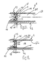
- Fig 9 Illustrated in Fig 9 is a part cross section of two adjacent dry cells 58 and 88 which have been correctly positioned in the housing 2, with a plan view of the arrangement being illustrated in fig 11.
- the raised cylindrical positive terminal 86 of the dry cell 88 partially passes through the U-shaped passage 36 to make electrical contact with the first portion 38 of the contact member 34.
- the terminal 86 needs to pass through passage 36 because first portion 38 is recessed relative to the external surface 40 of the wall part 28.
- another dry cell 58 is placed in the adjacent cavity so that its negative terminal 56 makes contact with the tab portion 52 and second part 46 of the contact member 34, as has been described previously.
- Fig 8 Illustrated in Fig 8 is a part cross section of two adjacent dry cells 58 and 88 which have been incorrectly positioned in the housing 2, with a plan view of the arrangement being illustrated in fig 10.
- the first portion 38 of contact member 34 is recessed and the external surface 40 of wall part 28 keeps the negative terminal 56 of the dry cell 58 from making contact with the recessed first portion 38, thus no electrical connection is made to the positive terminal 86 of dry cell 88.
- a positive terminal end 92 of an appliance (the rest of which is not illustrated) and an end of housing 2 with a correctly positioned dry cell 88.
- the positive terminal 86 of dry cell 88 protrudes past the external surface 18 of first end wall 8, so as to make contact with the positive contact 94 of the appliance.
- the positive terminal 86 and positive contact 94 are pushed together because of bias associated with the negative terminal of the appliance, which pushes against the negative terminal of a dry cell in cavity 62, which in turn pushes the whole housing 2 forward.
- Around the positive contact 94 are ribs 96 and 98 which are shown in cross section in Figure 12 (and 13).
- the ribs 96 and 98 could be replaced by a single rib, such as a U-shaped rib if desired.
- the ribs 96 and 98 are separated from external surface 18 by a gap 100.
- the gap 100 is also substantially equivalent to the distance which the positive terminal 86 protrudes past the external surface 18 of the first end wall 8.
- the gap 100 can be reduced or increased depending upon: the thickness of the first end wall 8, distance from the end of positive contact 94 to the end of the ribs 96 and 98. If desired the positive contact 94 could be spring mounted, in which case the gap 100 might not be present.
- Fig 13 Illustrated in Fig 13 is the positive terminal end 92 of the appliance of Fig 12, and a correctly positioned dry cell 58 in cavity 62, but the housing 2 has been inserted with its negative end pushed toward the positive contact 94.
- the second end wall 10 is adjacent the negative end 56 of the dry cell 58 positioned inside the cavity 62.
- the ribs 96 and 98 engage the external surface 26 of the second end wall 10. Because the surface of the terminal 56 is separated from the surface 26 of second end wall 10 (by the thickness 22 of the second end wall 10) the positive contact 94 does not make electrical contact with the negative terminal 56. By recessing the end of positive contact 94 from the end of the ribs 96 and 98, there will be even less chance that inappropriate contacts will be made.
- the construction of the intermediate wall 6 ensures that any dry cells incorrectly positioned into any one of cavities 62, 64, 66, 68, will not make electrical contact with an adjacent dry cell and thus no premature dissipation of the dry cells will take place. Further, interaction of the housing 2 at the first end wall 8 and second end wall 10 with the positive terminal end of an appliance ensures that even if all batteries or dry cells are correctly positioned inside each of the cavities 62, 64, 66, 68, if the housing 2 is inserted incorrectly into an appliance, then no circuit is formed with the series connected dry cells, thus providing protection for the appliance.
- the number of cavities provided can be varied according to usage. It could vary between 2 to 4, or more, dry cells per housing 2, depending upon the appliance.
- the housing 2 illustrated in the figures is of dimensions to receive AA-sized dry cells.
- the housing 2 and the cavities 62, 64, 66, 68 can be sized to accept any cylindrical dry cells, having terminals at two ends.
- the intermediate wall 6 describes the intermediate wall 6 as having two wall parts 28 & 30, a modified version can be manufactured by using a single wall part 28, with a passage therethrough.
- the contact member 34 of figure 14 by means of the first portion 38, can be riveted by means of a plastic rivet or attached by some other appropriate means, to one side of the wall part 28.
- the intermediate walls 6 can be increased in size, by such modifications as an increase in the thickness or depth of the wall part 30, together with a commensurate change in shape and or length of the second portion 42 of the contact member 34.
- the overall length of the housing 2 will increase. The length is increased so that it is appropriately longer than the length of the same number of dry cells connected end to end, which are meant to fit into the housing 2.
- the appliance will have its positive and negative terminals spaced so as to make electrical contact with the dry cell terminals at the ends of the housing 2. If a person were to place dry cells without using a housing 2, into the appliance cavity which would normally receive the housing 2, no simultaneous electrical contact will be made between each adjacent terminal of the dry cells and the positive and negative terminals of the appliance, because of the provision of spacing of the terminals of the appliance. Thereby, the appliance is protected and the chances will be very low of any of the dry cells prematurely dissipating or being impaired and thus not able to provide current as designed. Thus by providing a specially sized housing 2 with the appliance, the user will need to use the housing 2 thereby ensuring that the all the dry cells are correctly oriented for series connection.
- the placing of dry cells into the appliance with a housing as illustrated may still be of sufficient length to make simultaneous contact, because the appliance may provide a negative contact or terminal which can travel a significant distance and is spring biased. Such travel and biasing may make the necessary contact, with the bias being sufficient to complete the contacts of all the dry cells.
- thicker intermediate walls 6 can be provided to decrease the probability of simultaneous electrical contact of the terminals being made. The above describes how the correct orientation of the dry cells to be inserted in the cavities is assisted by the apertures 70.
Landscapes
- Chemical & Material Sciences (AREA)
- Chemical Kinetics & Catalysis (AREA)
- Electrochemistry (AREA)
- General Chemical & Material Sciences (AREA)
- Battery Mounting, Suspending (AREA)
- Connection Of Batteries Or Terminals (AREA)
Claims (25)
- Gehäuse mit einem allgemein langgestreckten Körper zum Zusammenhalten von mindestens zwei Trockenzellen in Serienverbindung in einer End- zu End- oder Reihenorientierung, und mit: einem ersten Ende mit einer ersten Endwand zur Aufnahme eines positiven Anschlusses einer Trockenzelle und einem zweiten Ende mit einer zweiten Endwand; zwei oder mehr Trockenzellen-Hohlräumen, die jeweils mindestens eine Seitenwand haben und weiterhin eine benachbarten Hohlräumen gemeinsame Zwischenwand haben, wobei die oder jede Zwischenwand mit einem Kontaktglied zusammenwirkt, das den positiven Anschluss einer Trockenzelle mit dem negativen Anschluss einer benachbarten Trockenzelle verbindet, wenn Trockenzellen in richtiger Orientierung in benachbarte Hohlräume gesetzt sind; die Zwischenwände haben oder enthalten einen Teil mit einer vorbestimmten Dicke und einem axialen Durchlass dadurch hindurch, wobei die Dicke kleiner als die Länge eines erhabenen zylindrischen positiven Anschlusses einer Trockenzelle ist und die Zwischenwände eine erste, in Richtung des zweiten Endes weisende Oberfläche und eine zweite, in Richtung des ersten Endes weisende Oberfläche haben; die oder jede Zwischenwand und das Kontaktglied sind so angeordnet, dass eine dem zweiten Ende gegenüberliegende Seite des Kontaktgliedes relativ zu der ersten Oberfläche vertieft ist, so dass ein erhabener zylindrischer positiver Anschluss einer Trockenzelle zumindest teilweise durch den Durchlass hindurchgehen muss, um elektrischen Kontakt mit dem Kontaktglied herzustellen, dadurch gekennzeichnet, dass das Gehäuse in ein Gerät einsetzbar und davon abnehmbar ist und die erste Endwand und die zweite Endwand jeweils einen Durchlass dadurch hindurch haben, um die Herstellung von elektrischem Kontakt durch Anschlüsse eines Gerätes mit Anschlüssen einer Trockenzelle an den ersten und zweiten Enden zu ermöglichen.
- Gehäuse nach Anspruch 1, bei dem der Durchlass durch die zweite Endwand mit der Oberfläche eines negativen Anschlusses einer Trockenzelle in dem Hohlraum an dem zweiten Ende zusammenwirkt, so dass bei richtiger Positionierung in dem Hohlraum die Oberfläche des negativen Anschlusses von der nach außen weisenden Oberfläche der zweiten Endwand her vertieft ist.
- Gehäuse nach Anspruch 1 oder 2, bei dem die Dicke der zweiten Endwand und ein Teil der Zwischenwand oder die Zwischenwand die Tiefe der Vertiefung bestimmt.
- Gehäuse nach einem der Ansprüche 1 bis 3, bei dem die Zwischenwände jeweils aus zwei Wandteilen mit einem Zwischenraum zwischen jedem Wandteil zur Aufnahme des Kontaktgliedes gestaltet sind, so dass eine Oberfläche oder ein Teil einer Oberfläche des Kontaktgliedes um die Dicke des Wandteils, der die erste Oberfläche enthält, von der ersten Oberfläche her vertieft ist.
- Gehäuse nach Anspruch 4, bei dem das Kontaktglied durch das Zusammenfügen jedes Wandteils an einem Ende in jeder Zwischenwand festgehalten wird, um den Zwischenraum zwischen den Wandteilen einzuschließen.
- Gehäuse nach einem der Ansprüche 1 bis 5, bei dem das Gehäuse einen allgemein halbkreisförmigen Körper hat, in dem die Trockenzellen-Hohlräume ausgebildet sind.
- Gehäuse nach einem der Ansprüche 1 bis 6, bei dem die Kontaktglieder eine zu dem Kontaktglied gehörende Vorspannungseinrichtung enthalten, um an einem negativen Anschuss einer Trockenzelle anzugreifen.
- Gehäuse nach Anspruch 4, bei dem das Kontaktglied mindestens einen winkligen Widerhaken enthält, der an einer der gegenüberliegenden Wandteile der Endwand angreift, wobei der Widerhaken winklig ist, um das Entfernen des Kontaktgliedes zu verhindern, sobald es in der Endwand positioniert worden ist.
- Gehäuse nach einem der Ansprüche 1 bis 8, bei dem der Durchlass durch die Zwischenwand und die ersten und zweiten Endwände eine allgemein U-förmige oder halbkreisförmige oder teilhalbkreisförmige Bauweise hat.
- Gehäuse nach einem der Ansprüche 1 bis 9, bei dem die erste Endwand halbkreisförmig ist.
- Gehäuse nach einem der Ansprüche 1 bis 10, bei dem die Zwischenwände einen allgemein kreisförmigen Umfang haben.
- Gehäuse nach einem der Ansprüche 1 bis 11, bei dem der Durchlass durch die Zwischenwände eine im wesentlichen U-förmige Bauweise hat.
- Gehäuse nach Anspruch 1 oder 2, bei dem die Zwischenwand aus einem einzelnen Wandteil besteht und das Kontaktglied an der zweiten Oberfläche befestigt ist, um das Kontaktglied von der ersten Oberfläche her zu vertiefen.
- Gehäuse nach einem der Ansprüche 1 bis 13, mit Haltegliedern, die mit den Seitenwänden zusammenwirken, wobei die Halteglieder beweglich sind, um das Einsetzen oder Entfernen einer Trockenzelle in die oder aus den Hohlräumen zu ermöglichen.
- Gehäuse nach Anspruch 14, bei dem die Halteglieder Verlängerungen des Körpers sind, die ein Volumen teilweise einschließen, um die Hohlräume auszubilden und zu verschließen.
- Gehäuse nach Anspruch 14 oder 15, bei dem der Körper eine Öffnung enthält, um etwas federnde Biegsamkeit zu erzeugen, um eine Bewegung der Halteglieder zu unterstützen, um das Anbringen und Entfernen der Trockenzellen zu ermöglichen.
- Gehäuse nach Anspruch 16, bei dem die Öffnung ein ähnliches Profil wie der Umriss einer Trockenzelle hat, wobei eine Darstellung eines positiven Anschlusses sichtbar ist.
- Gehäuse nach Anspruch 1, wobei die Hohlräume einen Körper-Teil mit mindestens einem Seitenwandteil enthalten, das Gehäuse einen zu jedem Hohlraum gehörenden Teil des Körpers mit einer geformten Öffnung dadurch hindurch enthält, die ein ähnliches Profil wie ein Umriss einer Trockenzelle hat, wobei ein Teil der Öffnung das positive Ende einer Trockenzelle darstellt, wobei der Teil der Öffnung und die Öffnung orientiert sind, um der richtigen Orientierung der Trockenzelle in dem Hohlraum zu entsprechen und diese anzuzeigen, wobei die Öffnung eine Größe hat, die verhindert, dass die Trockenzelle durch die Öffnung hindurchgeht.
- Gehäuse nach Anspruch 18, wobei das Gehäuse allgemein zylindrisch ist.
- Gehäuse nach Anspruch 18 oder 19, wobei das Gehäuse eine Halteeinrichtung zum lösbaren Festhalten der Trockenzellen in dem Hohlraum enthält.
- Gehäuse nach Anspruch 20, bei dem die geformte Öffnung mit der Halteeinrichtung zusammenwirkt, um die Halteeinrichtung in ihrer Beweglichkeit zu unterstützen, um das Entfernen oder Einsetzen der Trockenzellen aus dem oder in den Hohlraum zu ermöglichen.
- Gehäuse nach einem der Ansprüche 18 bis 21, bei dem die Öffnung beim Entfernen einer Trockenzelle aus dem Hohlraum mithilft.
- Gerät, das durch Trockenzellen angetrieben wird, die in einem Gehäuse nach den Ansprüchen 1 bis 17 seriell verbunden und montiert sind, wobei der positive Anschluss des Gerätes so gestaltet ist, dass er mindestens einen dazugehörenden Vorsprung hat, der an einer Außenfläche der zweiten Endwand des Gehäuses nach den Ansprüchen 1 bis 17 angreifen kann, um zu verhindern, dass der positive Anschluss des Gerätes Kontakt mit dem negativen Anschluss einer Trockenzelle in einem zu der zweiten Endwand des Gehäuses gehörenden Hohlraum herstellt.
- Gerät nach Anspruch 23, bei dem der mindestens eine Vorsprung außerdem an einer Außenfläche der ersten Endwand angreift, um zu verhindern, dass der positive Anschluss des Gerätes Kontakt mit dem negativen Anschluss einer unrichtig positionierten Trockenzelle in einem zu der ersten Endwand des Gehäuses gehörenden Trockenzellen-Hohlraum herstellt.
- Gerät in Kombination mit einem Gehäuse nach den Ansprüchen 1 bis 17, wobei das Gerät einen Gehäuseaufnahme-Hohlraum zur Aufnahme des Gehäuses hat, das Gerät einen positiven und einen negativen Anschluss zur elektrischen Verbindung mit ersten und zweiten Enden des Gehäuses enthält, das Gehäuse Zwischenwände enthält, die eine so große Dicke oder Tiefe haben, dass die Gesamtlänge des Gehäuses größer als die Länge der gleichen Anzahl von Trockenzellen ist, zu deren Aufnahme das Gehäuse bestimmt ist, wenn die gleiche Anzahl Trockenzellen in Reihe von Ende zu Ende verbunden sind, und der Gehäuseaufnahme-Hohlraum so groß ist, dass, wenn die Anzahl Trockenzellen ohne das Gehäuse in den Gehäuseaufnahme-Hohlraum gesetzt sind, der positive und negative Anschluss des Gerätes so weit voneinander beabstandet sind, dass keine gleichzeitige elektrische Verbindung zwischen allen Trockenzellen und den positiven und negativen Anschlüssen hergestellt werden kann.
Applications Claiming Priority (5)
| Application Number | Priority Date | Filing Date | Title |
|---|---|---|---|
| AU76519/96A AU723320B2 (en) | 1996-12-24 | 1996-12-24 | In-line dry cell cartridge or housing |
| AU7651996 | 1996-12-24 | ||
| CNB971809828A CN1226793C (zh) | 1996-12-24 | 1997-12-23 | 一线型干电池盒或套筒 |
| PCT/AU1997/000877 WO1998028803A1 (en) | 1996-12-24 | 1997-12-23 | In-line dry cell cartridge or housing |
| US09/338,073 US6238818B1 (en) | 1996-12-24 | 1999-06-23 | In-line dry cell cartridge or housing |
Publications (3)
| Publication Number | Publication Date |
|---|---|
| EP0958623A1 EP0958623A1 (de) | 1999-11-24 |
| EP0958623A4 EP0958623A4 (de) | 2000-03-22 |
| EP0958623B1 true EP0958623B1 (de) | 2003-03-19 |
Family
ID=27156205
Family Applications (1)
| Application Number | Title | Priority Date | Filing Date |
|---|---|---|---|
| EP97948651A Expired - Lifetime EP0958623B1 (de) | 1996-12-24 | 1997-12-23 | Einspurige trockenzellenpatrone oder gehäuse |
Country Status (5)
| Country | Link |
|---|---|
| US (1) | US6238818B1 (de) |
| EP (1) | EP0958623B1 (de) |
| CN (1) | CN1226793C (de) |
| AU (1) | AU723320B2 (de) |
| WO (1) | WO1998028803A1 (de) |
Families Citing this family (39)
| Publication number | Priority date | Publication date | Assignee | Title |
|---|---|---|---|---|
| US6521363B1 (en) * | 2000-04-21 | 2003-02-18 | Shih-Ping Yeh | Elastic sheet structure for the contact of a battery set |
| USD468259S1 (en) | 2001-02-08 | 2003-01-07 | Garrity Industries, Inc. | Inner sleeve for holding batteries for a flashlight |
| US7448497B2 (en) * | 2002-12-30 | 2008-11-11 | Fck, Llc. | Batteries, accessories, marketing bundles and marketing methods |
| US7018737B2 (en) * | 2003-02-10 | 2006-03-28 | Leapfrog Enterprises, Inc. | Battery pack including rechargeable batteries |
| USD487058S1 (en) | 2003-03-28 | 2004-02-24 | Brower M. Roberts | Battery pack |
| US7342770B2 (en) * | 2003-07-09 | 2008-03-11 | Maxwell Technologies, Inc. | Recyclable dry particle based adhesive electrode and methods of making same |
| US20060147712A1 (en) * | 2003-07-09 | 2006-07-06 | Maxwell Technologies, Inc. | Dry particle based adhesive electrode and methods of making same |
| US7791860B2 (en) | 2003-07-09 | 2010-09-07 | Maxwell Technologies, Inc. | Particle based electrodes and methods of making same |
| US20050250011A1 (en) * | 2004-04-02 | 2005-11-10 | Maxwell Technologies, Inc. | Particle packaging systems and methods |
| US7352558B2 (en) * | 2003-07-09 | 2008-04-01 | Maxwell Technologies, Inc. | Dry particle based capacitor and methods of making same |
| US7508651B2 (en) | 2003-07-09 | 2009-03-24 | Maxwell Technologies, Inc. | Dry particle based adhesive and dry film and methods of making same |
| US7920371B2 (en) | 2003-09-12 | 2011-04-05 | Maxwell Technologies, Inc. | Electrical energy storage devices with separator between electrodes and methods for fabricating the devices |
| US7495349B2 (en) * | 2003-10-20 | 2009-02-24 | Maxwell Technologies, Inc. | Self aligning electrode |
| US6952338B1 (en) * | 2003-11-07 | 2005-10-04 | Sony Corporation | Common pole capacitor housing apparatus and method |
| US7384433B2 (en) | 2004-02-19 | 2008-06-10 | Maxwell Technologies, Inc. | Densification of compressible layers during electrode lamination |
| US7090946B2 (en) | 2004-02-19 | 2006-08-15 | Maxwell Technologies, Inc. | Composite electrode and method for fabricating same |
| US7492574B2 (en) | 2005-03-14 | 2009-02-17 | Maxwell Technologies, Inc. | Coupling of cell to housing |
| US7440258B2 (en) | 2005-03-14 | 2008-10-21 | Maxwell Technologies, Inc. | Thermal interconnects for coupling energy storage devices |
| JP2009520330A (ja) * | 2005-12-15 | 2009-05-21 | マックスウェル テクノロジーズ, インク | 電気モジュール |
| US8518573B2 (en) * | 2006-09-29 | 2013-08-27 | Maxwell Technologies, Inc. | Low-inductive impedance, thermally decoupled, radii-modulated electrode core |
| US20080201925A1 (en) | 2007-02-28 | 2008-08-28 | Maxwell Technologies, Inc. | Ultracapacitor electrode with controlled sulfur content |
| US9478785B2 (en) * | 2007-04-27 | 2016-10-25 | Microsoft Technology Licensing, Llc | Polarity protection for multiple batteries |
| US8659246B2 (en) | 2010-02-23 | 2014-02-25 | Homerun Holdings Corporation | High efficiency roller shade |
| US8575872B2 (en) | 2010-02-23 | 2013-11-05 | Homerun Holdings Corporation | High efficiency roller shade and method for setting artificial stops |
| US9249623B2 (en) | 2010-02-23 | 2016-02-02 | Qmotion Incorporated | Low-power architectural covering |
| US9194179B2 (en) | 2010-02-23 | 2015-11-24 | Qmotion Incorporated | Motorized shade with the transmission wire passing through the support shaft |
| CN101882672B (zh) * | 2010-06-22 | 2014-04-30 | 海洋王照明科技股份有限公司 | 一种灯具用电池盒及灯具 |
| US10008872B2 (en) | 2010-09-20 | 2018-06-26 | Batteroo, Inc. | Methods of extending the life of battery |
| US20120121943A1 (en) | 2010-09-20 | 2012-05-17 | Fariborz Frankie Roohparvar | Structure and Method for Extending Battery Life |
| US8968900B2 (en) * | 2011-03-01 | 2015-03-03 | Qmotion Incorporated | Flexible sleeve battery holder apparatus and method |
| CN103137926A (zh) * | 2013-03-13 | 2013-06-05 | 宁波超霸能源有限公司 | 一种6v锂电池 |
| EP3119218B1 (de) * | 2014-03-19 | 2019-11-06 | Philip Morris Products S.a.s. | Monolithische ebene mit elektrischen kontakten und herstellungsverfahren dafür |
| US9954205B2 (en) | 2016-04-12 | 2018-04-24 | Energizer Brands, Llc | Slotted battery cavity for multiple cell sizes |
| USD955033S1 (en) | 2019-03-29 | 2022-06-14 | Technomate Manufactory Limited | Lens apparatus for use with flashlights |
| US10914434B2 (en) * | 2019-03-29 | 2021-02-09 | Technomate Manufactory Limited | Flashlight apparatus and battery cartridge for the flashlight apparatus |
| USD959729S1 (en) | 2019-03-29 | 2022-08-02 | Technomate Manufactory Limited | Lens for flashlights |
| USD957722S1 (en) | 2019-03-29 | 2022-07-12 | Technomate Manufactory Limited | Lens for flashlights |
| USD972755S1 (en) | 2020-09-15 | 2022-12-13 | Technomate Manufactory Limited | Flashlight |
| USD970073S1 (en) | 2020-09-15 | 2022-11-15 | Technomate Manufactory Limited | Flashlight |
Family Cites Families (11)
| Publication number | Priority date | Publication date | Assignee | Title |
|---|---|---|---|---|
| US4265984A (en) * | 1980-02-11 | 1981-05-05 | Duracell International Inc. | Battery housing |
| US4530034A (en) | 1982-11-26 | 1985-07-16 | Olympus Optical Company Ltd. | Battery containment apparatus for electronic flash |
| FR2562722B1 (fr) | 1984-04-06 | 1987-04-24 | Black & Decker Inc | Procede et dispositif pour la fabrication d'un ensemble accumulateur electrique comprenant une pluralite d'elements accumulateurs rechargeables |
| US4595641A (en) * | 1985-05-21 | 1986-06-17 | Cordis Corporation | Battery compartment having battery polarity protection |
| JPS6240155A (ja) | 1985-08-13 | 1987-02-21 | Nippon Kogaku Kk <Nikon> | 電池収納装置 |
| JP3041000B2 (ja) * | 1989-04-04 | 2000-05-15 | 株式会社ニッコー | 無線操縦走行玩具の電池収納部 |
| US5229220A (en) * | 1991-12-12 | 1993-07-20 | Motorola, Inc. | Reverse polarity protection assembly |
| JPH07105923A (ja) * | 1993-10-01 | 1995-04-21 | Matsushita Electric Ind Co Ltd | 電池収納装置 |
| JPH07321890A (ja) * | 1994-05-26 | 1995-12-08 | Nec Kansai Ltd | 電池収納構体 |
| US5631098A (en) * | 1994-09-06 | 1997-05-20 | Nikon Corporation | Battery holder |
| US5607322A (en) * | 1995-11-13 | 1997-03-04 | Century Products Company | One-way battery receptacle |
-
1996
- 1996-12-24 AU AU76519/96A patent/AU723320B2/en not_active Ceased
-
1997
- 1997-12-23 WO PCT/AU1997/000877 patent/WO1998028803A1/en not_active Ceased
- 1997-12-23 CN CNB971809828A patent/CN1226793C/zh not_active Expired - Fee Related
- 1997-12-23 EP EP97948651A patent/EP0958623B1/de not_active Expired - Lifetime
-
1999
- 1999-06-23 US US09/338,073 patent/US6238818B1/en not_active Expired - Fee Related
Also Published As
| Publication number | Publication date |
|---|---|
| EP0958623A4 (de) | 2000-03-22 |
| EP0958623A1 (de) | 1999-11-24 |
| US6238818B1 (en) | 2001-05-29 |
| AU723320B2 (en) | 2000-08-24 |
| CN1242109A (zh) | 2000-01-19 |
| WO1998028803A1 (en) | 1998-07-02 |
| AU7651996A (en) | 1998-06-25 |
| CN1226793C (zh) | 2005-11-09 |
Similar Documents
| Publication | Publication Date | Title |
|---|---|---|
| EP0958623B1 (de) | Einspurige trockenzellenpatrone oder gehäuse | |
| US4213078A (en) | Battery holder and connector for a radio receiver or the like | |
| US5537022A (en) | Enclosed battery holder | |
| EP0572327B2 (de) | Batteriepatrone mit Aussparungen zur Kontrolle des richtigen Aufsetzens der Patrone auf ein Batterieladegerät | |
| KR100415243B1 (ko) | 배터리장치및배터리장치용장착장치 | |
| KR101547852B1 (ko) | 부정확한 배터리 극성에 대한 보호 | |
| JP5805705B2 (ja) | 複数の電池の極性保護 | |
| EP0778627A1 (de) | Batteriesatz | |
| US4083011A (en) | Battery holder and connector for a radio receiver or the like | |
| CN101222031A (zh) | 电池装置及电子设备 | |
| KR100807412B1 (ko) | 서로 다른 타입의 전원을 사용하는데 적합한, 휴대 장치용전원 장치 | |
| AU723206B2 (en) | In-line dry cell cartridge or housing | |
| JPH0718347U (ja) | 電池保持構造 | |
| CA2272571A1 (en) | In-line dry cell cartridge or housing | |
| MXPA99005060A (en) | In-line dry cell cartridge or housing | |
| JP2002063879A (ja) | 電池アダプタケース | |
| JP2005085543A (ja) | 薄型バッテリーパック | |
| JP2003018753A (ja) | 充電装置及び二次電池 | |
| JPH0877992A (ja) | 電池の逆通電防止機構 | |
| CN117879101B (zh) | 可用作充电宝的电池充电器 | |
| JPS596606Y2 (ja) | 小型ヒユ−ズ | |
| CN222602086U (zh) | 医疗设备充电装置 | |
| JP2563834Y2 (ja) | 電池ケース | |
| JPH065118U (ja) | 二次電池およびこの二次電池を充電するための充電装置 | |
| JP2659687B2 (ja) | 充電器 |
Legal Events
| Date | Code | Title | Description |
|---|---|---|---|
| PUAI | Public reference made under article 153(3) epc to a published international application that has entered the european phase |
Free format text: ORIGINAL CODE: 0009012 |
|
| 17P | Request for examination filed |
Effective date: 19990628 |
|
| AK | Designated contracting states |
Kind code of ref document: A1 Designated state(s): AT BE CH DE DK ES FI FR GB GR IE IT LI LU MC NL PT SE |
|
| A4 | Supplementary search report drawn up and despatched |
Effective date: 20000204 |
|
| AK | Designated contracting states |
Kind code of ref document: A4 Designated state(s): AT BE CH DE DK ES FI FR GB GR IE IT LI LU MC NL PT SE |
|
| 17Q | First examination report despatched |
Effective date: 20011221 |
|
| GRAG | Despatch of communication of intention to grant |
Free format text: ORIGINAL CODE: EPIDOS AGRA |
|
| GRAG | Despatch of communication of intention to grant |
Free format text: ORIGINAL CODE: EPIDOS AGRA |
|
| GRAH | Despatch of communication of intention to grant a patent |
Free format text: ORIGINAL CODE: EPIDOS IGRA |
|
| GRAH | Despatch of communication of intention to grant a patent |
Free format text: ORIGINAL CODE: EPIDOS IGRA |
|
| GRAA | (expected) grant |
Free format text: ORIGINAL CODE: 0009210 |
|
| AK | Designated contracting states |
Designated state(s): AT BE CH DE DK ES FI FR GB GR IE IT LI LU MC NL PT SE |
|
| PG25 | Lapsed in a contracting state [announced via postgrant information from national office to epo] |
Ref country code: NL Free format text: LAPSE BECAUSE OF FAILURE TO SUBMIT A TRANSLATION OF THE DESCRIPTION OR TO PAY THE FEE WITHIN THE PRESCRIBED TIME-LIMIT Effective date: 20030319 Ref country code: LI Free format text: LAPSE BECAUSE OF FAILURE TO SUBMIT A TRANSLATION OF THE DESCRIPTION OR TO PAY THE FEE WITHIN THE PRESCRIBED TIME-LIMIT Effective date: 20030319 Ref country code: IT Free format text: LAPSE BECAUSE OF FAILURE TO SUBMIT A TRANSLATION OF THE DESCRIPTION OR TO PAY THE FEE WITHIN THE PRESCRIBED TIME-LIMIT;WARNING: LAPSES OF ITALIAN PATENTS WITH EFFECTIVE DATE BEFORE 2007 MAY HAVE OCCURRED AT ANY TIME BEFORE 2007. THE CORRECT EFFECTIVE DATE MAY BE DIFFERENT FROM THE ONE RECORDED. Effective date: 20030319 Ref country code: GR Free format text: LAPSE BECAUSE OF FAILURE TO SUBMIT A TRANSLATION OF THE DESCRIPTION OR TO PAY THE FEE WITHIN THE PRESCRIBED TIME-LIMIT Effective date: 20030319 Ref country code: FI Free format text: LAPSE BECAUSE OF FAILURE TO SUBMIT A TRANSLATION OF THE DESCRIPTION OR TO PAY THE FEE WITHIN THE PRESCRIBED TIME-LIMIT Effective date: 20030319 Ref country code: CH Free format text: LAPSE BECAUSE OF FAILURE TO SUBMIT A TRANSLATION OF THE DESCRIPTION OR TO PAY THE FEE WITHIN THE PRESCRIBED TIME-LIMIT Effective date: 20030319 Ref country code: BE Free format text: LAPSE BECAUSE OF FAILURE TO SUBMIT A TRANSLATION OF THE DESCRIPTION OR TO PAY THE FEE WITHIN THE PRESCRIBED TIME-LIMIT Effective date: 20030319 Ref country code: AT Free format text: LAPSE BECAUSE OF FAILURE TO SUBMIT A TRANSLATION OF THE DESCRIPTION OR TO PAY THE FEE WITHIN THE PRESCRIBED TIME-LIMIT Effective date: 20030319 |
|
| REG | Reference to a national code |
Ref country code: GB Ref legal event code: FG4D |
|
| REG | Reference to a national code |
Ref country code: CH Ref legal event code: EP |
|
| REG | Reference to a national code |
Ref country code: IE Ref legal event code: FG4D |
|
| REF | Corresponds to: |
Ref document number: 69720060 Country of ref document: DE Date of ref document: 20030424 Kind code of ref document: P |
|
| PG25 | Lapsed in a contracting state [announced via postgrant information from national office to epo] |
Ref country code: SE Free format text: LAPSE BECAUSE OF FAILURE TO SUBMIT A TRANSLATION OF THE DESCRIPTION OR TO PAY THE FEE WITHIN THE PRESCRIBED TIME-LIMIT Effective date: 20030619 Ref country code: DK Free format text: LAPSE BECAUSE OF FAILURE TO SUBMIT A TRANSLATION OF THE DESCRIPTION OR TO PAY THE FEE WITHIN THE PRESCRIBED TIME-LIMIT Effective date: 20030619 |
|
| PG25 | Lapsed in a contracting state [announced via postgrant information from national office to epo] |
Ref country code: PT Free format text: LAPSE BECAUSE OF FAILURE TO SUBMIT A TRANSLATION OF THE DESCRIPTION OR TO PAY THE FEE WITHIN THE PRESCRIBED TIME-LIMIT Effective date: 20030620 |
|
| NLV1 | Nl: lapsed or annulled due to failure to fulfill the requirements of art. 29p and 29m of the patents act | ||
| PG25 | Lapsed in a contracting state [announced via postgrant information from national office to epo] |
Ref country code: ES Free format text: LAPSE BECAUSE OF FAILURE TO SUBMIT A TRANSLATION OF THE DESCRIPTION OR TO PAY THE FEE WITHIN THE PRESCRIBED TIME-LIMIT Effective date: 20030930 |
|
| REG | Reference to a national code |
Ref country code: CH Ref legal event code: PL |
|
| ET | Fr: translation filed | ||
| PG25 | Lapsed in a contracting state [announced via postgrant information from national office to epo] |
Ref country code: LU Free format text: LAPSE BECAUSE OF NON-PAYMENT OF DUE FEES Effective date: 20031223 Ref country code: IE Free format text: LAPSE BECAUSE OF NON-PAYMENT OF DUE FEES Effective date: 20031223 |
|
| PG25 | Lapsed in a contracting state [announced via postgrant information from national office to epo] |
Ref country code: MC Free format text: LAPSE BECAUSE OF NON-PAYMENT OF DUE FEES Effective date: 20031231 |
|
| PLBE | No opposition filed within time limit |
Free format text: ORIGINAL CODE: 0009261 |
|
| STAA | Information on the status of an ep patent application or granted ep patent |
Free format text: STATUS: NO OPPOSITION FILED WITHIN TIME LIMIT |
|
| 26N | No opposition filed |
Effective date: 20031222 |
|
| REG | Reference to a national code |
Ref country code: IE Ref legal event code: MM4A |
|
| REG | Reference to a national code |
Ref country code: HK Ref legal event code: WD Ref document number: 1023851 Country of ref document: HK |
|
| PGFP | Annual fee paid to national office [announced via postgrant information from national office to epo] |
Ref country code: DE Payment date: 20070131 Year of fee payment: 10 |
|
| PGFP | Annual fee paid to national office [announced via postgrant information from national office to epo] |
Ref country code: GB Payment date: 20071227 Year of fee payment: 11 |
|
| PGFP | Annual fee paid to national office [announced via postgrant information from national office to epo] |
Ref country code: FR Payment date: 20071217 Year of fee payment: 11 |
|
| PG25 | Lapsed in a contracting state [announced via postgrant information from national office to epo] |
Ref country code: DE Free format text: LAPSE BECAUSE OF NON-PAYMENT OF DUE FEES Effective date: 20080701 |
|
| GBPC | Gb: european patent ceased through non-payment of renewal fee |
Effective date: 20081223 |
|
| REG | Reference to a national code |
Ref country code: FR Ref legal event code: ST Effective date: 20090831 |
|
| PG25 | Lapsed in a contracting state [announced via postgrant information from national office to epo] |
Ref country code: GB Free format text: LAPSE BECAUSE OF NON-PAYMENT OF DUE FEES Effective date: 20081223 |
|
| PG25 | Lapsed in a contracting state [announced via postgrant information from national office to epo] |
Ref country code: FR Free format text: LAPSE BECAUSE OF NON-PAYMENT OF DUE FEES Effective date: 20081231 |