EP0957533B1 - Antennenkombination - Google Patents
Antennenkombination Download PDFInfo
- Publication number
- EP0957533B1 EP0957533B1 EP97946817A EP97946817A EP0957533B1 EP 0957533 B1 EP0957533 B1 EP 0957533B1 EP 97946817 A EP97946817 A EP 97946817A EP 97946817 A EP97946817 A EP 97946817A EP 0957533 B1 EP0957533 B1 EP 0957533B1
- Authority
- EP
- European Patent Office
- Prior art keywords
- coaxial line
- antenna
- helical
- connecting terminal
- balun
- Prior art date
- Legal status (The legal status is an assumption and is not a legal conclusion. Google has not performed a legal analysis and makes no representation as to the accuracy of the status listed.)
- Expired - Lifetime
Links
Images


Classifications
-
- H—ELECTRICITY
- H01—ELECTRIC ELEMENTS
- H01Q—ANTENNAS, i.e. RADIO AERIALS
- H01Q21/00—Antenna arrays or systems
- H01Q21/30—Combinations of separate antenna units operating in different wavebands and connected to a common feeder system
-
- H—ELECTRICITY
- H01—ELECTRIC ELEMENTS
- H01Q—ANTENNAS, i.e. RADIO AERIALS
- H01Q1/00—Details of, or arrangements associated with, antennas
- H01Q1/12—Supports; Mounting means
- H01Q1/22—Supports; Mounting means by structural association with other equipment or articles
- H01Q1/24—Supports; Mounting means by structural association with other equipment or articles with receiving set
- H01Q1/241—Supports; Mounting means by structural association with other equipment or articles with receiving set used in mobile communications, e.g. GSM
- H01Q1/242—Supports; Mounting means by structural association with other equipment or articles with receiving set used in mobile communications, e.g. GSM specially adapted for hand-held use
- H01Q1/243—Supports; Mounting means by structural association with other equipment or articles with receiving set used in mobile communications, e.g. GSM specially adapted for hand-held use with built-in antennas
- H01Q1/244—Supports; Mounting means by structural association with other equipment or articles with receiving set used in mobile communications, e.g. GSM specially adapted for hand-held use with built-in antennas extendable from a housing along a given path
-
- H—ELECTRICITY
- H01—ELECTRIC ELEMENTS
- H01Q—ANTENNAS, i.e. RADIO AERIALS
- H01Q11/00—Electrically-long antennas having dimensions more than twice the shortest operating wavelength and consisting of conductive active radiating elements
- H01Q11/02—Non-resonant antennas, e.g. travelling-wave antenna
- H01Q11/08—Helical antennas
-
- H—ELECTRICITY
- H01—ELECTRIC ELEMENTS
- H01Q—ANTENNAS, i.e. RADIO AERIALS
- H01Q21/00—Antenna arrays or systems
- H01Q21/29—Combinations of different interacting antenna units for giving a desired directional characteristic
-
- H—ELECTRICITY
- H01—ELECTRIC ELEMENTS
- H01Q—ANTENNAS, i.e. RADIO AERIALS
- H01Q5/00—Arrangements for simultaneous operation of antennas on two or more different wavebands, e.g. dual-band or multi-band arrangements
- H01Q5/30—Arrangements for providing operation on different wavebands
- H01Q5/307—Individual or coupled radiating elements, each element being fed in an unspecified way
- H01Q5/342—Individual or coupled radiating elements, each element being fed in an unspecified way for different propagation modes
- H01Q5/35—Individual or coupled radiating elements, each element being fed in an unspecified way for different propagation modes using two or more simultaneously fed points
-
- H—ELECTRICITY
- H01—ELECTRIC ELEMENTS
- H01Q—ANTENNAS, i.e. RADIO AERIALS
- H01Q5/00—Arrangements for simultaneous operation of antennas on two or more different wavebands, e.g. dual-band or multi-band arrangements
- H01Q5/50—Feeding or matching arrangements for broad-band or multi-band operation
-
- H—ELECTRICITY
- H01—ELECTRIC ELEMENTS
- H01Q—ANTENNAS, i.e. RADIO AERIALS
- H01Q9/00—Electrically-short antennas having dimensions not more than twice the operating wavelength and consisting of conductive active radiating elements
- H01Q9/04—Resonant antennas
- H01Q9/30—Resonant antennas with feed to end of elongated active element, e.g. unipole
Definitions
- the present invention relates to a composite antenna apparatus for transmitting and receiving different frequencies and which is capable of providing a plurality of mobile communication services on differing frequency bands with a single portable terminal.
- Diagram 1 is a perspective diagram showing the components, in simplified form, of a kind of composite antenna apparatus known as a mobile-use 2-cycle shared double whip antenna as an example of a conventional mobile terminal antenna similar to that disclosed at the 1994 Electronic Communications Conference Autumn Session Exhibit B-73.
- reference numeral 1 represents the body of the portable terminal
- 2 is a first antenna joined to the body 1
- 3 is a second antenna joined in a similar fashion.
- the first antenna 2 has a length h 1 , about half the wavelength of the low frequency f 1 and the second antenna 3 has a length h 2 about half the wavelength of the high frequency f 2 .
- signals at a low frequency f 1 and signals at a high frequency f 2 are fed to the first antenna 2 and the second antenna 3 respectively.
- Diagrams 2 and 3 are explanatory views showing, respectively, the vertical plane of the emission pattern, calculated according to the law of moments, of the effect of the first antenna 2 short circuiting when the second antenna is fed and of the effect of the second antenna 3 short circuiting when the first antenna 2 is fed.
- diagram 2 shows that there is little effect due to the first antenna 2 short circuiting when the second antenna 3 is fed, as can be seen from diagram 3, when the second antenna 3 short circuits after the first antenna 2 is fed, the emission pattern changes greatly from the normal dipole antenna emission pattern due to the influence of the second antenna 3.
- the second antenna 3 may influence the other antenna (the first antenna 2) while the first antenna 2 is being fed with the result the that the emission pattern is changed greatly from a normal dipole antenna emission pattern, the problem arises that gain in the horizontal plane is reduced and so the antenna is unsuitable for a portable terminal used by a person communicating in a random environment in all horizontal directions.
- the purpose of the present invention is to solve the above mentioned problems by the provision of a composite antenna apparatus having antennas corresponding respectively to two different mobile communication services on the same axis.
- the respective antennas have equivalent gain in the horizontal plane as well as a reduced occupied volume.
- US 4,008,479 discusses a dual-frequency circularly polarized spiral antenna.
- the antenna is adapted to produce substantially omnidirectional horizontal coverage and substantially hemispherical vertical coverage at two or more operating frequencies.
- the antenna comprises cylindrically interleaved sets of spiral conductors of different lengths connected to a central coaxial transmission line feed system. This enables the antenna to operate at different frequencies and achieve good horizontal and vertical coverage.
- the composite antenna apparatus of the invention according to the scope of claim 1 provides for, at one end of a coaxial line, a balun, connected to an inner conductor and connected to the balun, one end of a helical element formed by a pair of line conductors.
- the other end of the helical element is aligned symmetrically, facing the balun, by turning it around the coaxial line using the coaxial line as a center and connected to the outer conductor at the other end of the coaxial line where the inner conductor connecting terminal joined to the inner conductor and the outer conductor connecting terminal joined to the outer conductor are located, a monopole antenna created by the outer conductor of said coaxial line and a two-wire wound helical antenna fed by said coaxial line and constructed by a pair of helical elements and a single coaxial line.
- the composite antenna apparatus formed by the helical antenna fed by the coaxial line and the monopole antenna created by the outer conductor of the coaxial line running through its center are constructed on the same axis, thus allowing equivalent gain in the horizontal plane and a reduction in the occupied volume.
- a composite antenna apparatus having equivalent gain in the horizontal plane and a reduction in the occupied volume can easily be constructed.
- the composite antenna apparatus of the invention includes, on the same axis, a monopole antenna created by the outer conductor of the coaxial line and a four-wire wound helical antenna fed by the coaxial line.
- the helical antenna is formed by providing a balun and a phase delay element on one end of a single coaxial line, one end of a first helical element is connected directly to the balun and an end of a second helical element is connected to the balun through the phase delay element. In this way, it is possible to improve the symmetry of the emission pattern and provide more equivalent gain in the horizontal plane.
- the composite antenna apparatus of the invention includes, on the same axis, a monopole antenna created by the outer conductor of the coaxial line and a plurality of helical antennas formed by grouping a plurality of coaxial lines so that the outer conductors are in mutual contact, placing a balun at the end of each coaxial line, connecting one end of the helical element to each balun and connecting the other end of the helical element to the outer conductor at the other end of the coaxial line.
- antennas corresponding respectively to a plurality of different kinds of services as well as providing equivalent gain in the horizontal plane and reduced occupied volume.
- the composite antenna apparatus of the invention includes, on a single axis, a monopole antenna created by the outer conductor of the coaxial line and two four-wire wound helical antennas formed by providing a first phase delay element and a first balun at one end of a first coaxial line and a second phase delay element and a second balun at one end of a second coaxial line, one end of the two pairs of helical elements forming the first helical antenna is connected to the first balun either directly or through the first phase delay element and one end of the two pairs of helical elements forming the second helical antenna is connected to the second balun either directly or through the second phase delay element.
- the composite antenna apparatus of the invention according to the scope of claim 5 provides an outer conductor connecting terminal connected to the outer conductor and an inner conductor connecting terminal connected to the inner conductor of the coaxial line placing at one end of the coaxial line mutually insulated slide-action contactors rotatable around the center of the axis of rotation orthogonal to the axis of the coaxial line.
- the composite antenna apparatus when not in use, may be piled and compacted within the wireless body, thus improving its portability.
- the composite antenna apparatus of the invention provides an antenna composed of helical and monopole antennas being both extendable and storable, their upper ends being electrically insulated from the coaxial line and sub-antennas being arranged in series.
- one of the wireless circuits is connected to the connecting terminal of the sub-antenna element.
- the wireless circuit connected to the connecting terminal of the sub-antenna element when in the stored position is connected to the outer conductor connecting terminal and the other wireless circuit is connected between the outer and inner conductor connecting terminals.
- gain is ensured by feeding the sub-antenna element.
- the composite antenna apparatus of the invention uses a helical conductor made by winding a wire conductor into a helical shape as a sub-antenna element.
- the sub-antenna can act as a helical monopole antenna thus ensuring gain when in the stored position.
- the composite antenna apparatus of the invention uses a bent conductor formed from a zigzag shaped wire conductor as a sub-antenna element.
- Diagram 4 is a perspective view showing the simplified structure of the composite antenna apparatus according to embodiment 1 of the invention and shows schematically the composite antenna apparatus used with a portable terminal as the combination, on the same axis, of a monopole antenna created by the outer conductor of the coaxial line and the helical antenna fed by said coaxial line.
- 11 is the coaxial line
- 12 is the inner conductor of said coaxial line
- similarly 13 is its outer conductor
- 14 is the inner conductor connecting terminal connected to the inner conductor 12 at one end of the coaxial line
- 15 is the outer conductor connecting terminal connected to the outer conductor 13 at the same end as the inner conductor connecting terminal 14 of the coaxial line 11.
- 16 is the balun which is placed at the end opposite the outer conductor connecting terminal 14 and the inner conductor connecting terminal 15 on the coaxial line 11 and is connected to the inner conductor 12 on said coaxial line 11.
- 17 is a helical element formed from the pair of wire conductors. One end of the helical element 17 is connected to the balun 16, the other end is symmetrically aligned facing the balun 16 by turning it around the coaxial line using the coaxial line as a center and is connected to the outer conductor 13 of the coaxial line 11 at the end to which the outer conductor connecting terminal 15 and the inner conducting connecting terminal of said coaxial line 11 are attached.
- the helical element 17 is formed by a helical antenna fed by the coaxial line 11 to which the second wireless circuit 19 is connected through the outer conductor connecting terminal 15 and the inner conductor connecting terminal 14. Modal variation between the pair of helical elements 17 and the coaxial line 11 in the helical antenna are carried out by the balun 16 placed between the helical element 17 and the inner conductor 12 of the coaxial line 11. Since the helical antenna generates a conical beam in the direction of the axis of the coaxial line 11, equivalent gain is achieved in the same horizontal plane.
- the outer conductor 13 of the coaxial line 11 to which the first wireless circuit 18 is connected through the outer conductor connecting terminal 15 functions as a monopole antenna element thus creating a non-directional antenna in the horizontal plane.
- the antenna structure displays line symmetry with respect to the coaxial line due to the fact that the helical element 17 in the helical antenna symmetrically winds around the coaxial line 11 and a monopole antenna is created by the outer conductor 13 of the coaxial line 11 acting as an antenna element.
- the axes with respect to the emission pattern correspond and thus create respectively non-directional antennas in the horizontal plane.
- a composite antenna apparatus comprised, on the same axis, by a helical antenna created by a pair of helical elements 17 fed by the coaxial line 11 and by a monopole antenna consisting of the outer conductor 13 running through the center of the helical antenna acting as an antenna element, equivalent gain is achieved in the horizontal plane and occupied volume is decreased.
- a composite antenna apparatus for use with a portable terminal comprised of a two-wire wound helical antenna using a pair of helical elements and a monopole antenna created by the outer conductor of the coaxial line was explained. It is possible, however, to combine, on the same axis, four-wire wound helical antenna using two pairs of helical elements and a monopole antenna created by the outer conductor of the coaxial line.
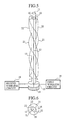
- Diagram 5 is a perspective view showing the schematic structure of a composite antenna apparatus according to the second embodiment of the invention.
- Diagram 6 is a schematic plan view of the connection of the central conductor of the coaxial line with the helical element.
- 11 is the coaxial line
- 12 is its inner conductor
- 13 is its outer conductor
- 14 is the inner conductor connecting terminal
- 15 is the outer conductor connecting terminal
- 16 is the balun
- 18 is the first wireless circuit
- 19 is the second wireless circuit.
- 20 is a phase delay element placed at the end opposite to that of the outer conductor connecting terminal 15 and the inner conductor connecting terminal 14 of the coaxial line 11 and is connected to the balun 16 which is in turn connected to the inner conductor of the said coaxial line 11.
- 21 is the first helical element formed from a pair of wire conductors and, in a similar manner to the helical element 17 in the first embodiment, is directly connected at one end to the balun 16.
- 22 is the second helical element formed from a pair of wire conductors and is connected at one end to the balun 16 through the phase delay element 20.
- first helical element 21 and the second helical element 22 are aligned symmetrically facing the balun 16 and the phase delay element 20 by turning them around the coaxial line 11 using the line as a center and are connected to the outer conductor 13 of the coaxial line 11 at the end to which the inner conductor connecting terminal 14 and the outer conductor connecting terminal 15 of said coaxial line 11 are attached.
- the second wireless circuit 19 is fed, only via the balun 16, by the coaxial line 11 connected between the outer conductor connecting terminal 15 and the inner conductor connecting terminal 14.
- the second wireless circuit 19 is fed, via the balun 16 and the phase delay element 20, by the coaxial line 11 connected between the inner conductor connecting terminal 14 and the outer conductor connecting terminal 15.
- Modal variation between the coaxial line 11 and the first and second helical elements 21, 22 in the helical antenna are carried out by the balun 16.
- the second helical element 22 receives a fixed phase delay from the phase delay element 20 and is fed at the delayed phase by the first helical element 21. Therefore the present helical antenna generates a more symmetrical conical beam with respect to the coaxial line 11 when compared to the two wire wound helical antenna in the first embodiment.
- the outer conductor 13 of the coaxial line 11 to which the first wireless circuit 18 is connected through the outer conductor connecting terminal 15 functions as a monopole antenna element in the same way as in the first embodiment and thus creates a non-directional antenna in the horizontal plane.
- the first and second helical elements 21, 22 of the helical antenna turn symmetrically around the coaxial line 11 and a monopole antenna is created by the outer conductor 13 of the coaxial line 11 functioning as an antenna element. Therefore the structure of the antenna displays line symmetry with respect to the coaxial line and the axes correspond as regards the emission pattern and therefore creates a non-directional antenna in the horizontal plane.
- 23 is the first of the two coaxial lines mentioned above and is coilingly disposed in electrical connection with the outer connector 13.
- 24 is the second of the aforementioned pair of coaxial lines.
- 25 a first inner conductor connecting terminal connected to the inner conductor 12 at one end of the first coaxial line
- 26 is a second inner conductor connecting terminal connected to the inner conductor 12 at one end of the second coaxial line
- 27 is an outer conductor connecting terminal which is connected to the outer conductor 13 at one end of the first coaxial line 23 and the second coaxial line 24.
- 28 is a first balun connected to the inner conductor 12 of said first coaxial line 23 at the end opposite to the first outer conductor connecting terminal 27 and the inner conductor connecting terminal 25 of the first coaxial line 23.
- 29 is a first phase delay element connected to the inner conductor 12 of the first coaxial line 23 through the first balun 28.
- 30 is a second balun connected to the inner conductor 12 of said second coaxial line 24 at the end opposite to the second outer conductor connecting terminal 27 and the inner conductor connecting terminal 26 of the second coaxial line 24.
- 31 is a second phase delay element connected to the inner conductor 12 of the second coaxial line 24 through the second balun 30.
- the 34 is a third wireless circuit connected to the inner conductor 12 of the second coaxial line 24 through the second inner conductor connecting terminal 26 and to the outer conductor 13 of the first and second coaxial lines 23, 24 through the outer conductor connecting terminal 27.
- the first wireless circuit 18 is connected to the outer conductor 13 of the first and second coaxial lines 23,24 through the outer conductor connecting terminal 27.
- the second wireless circuit 19 is connected respectively to the inner conductor 12 of the first coaxial line 23 through the first outer conductor connecting terminal 25 and to the outer conductor 13 of the first and second coaxial lines 23,24 through the outer conductor connecting terminal 27.
- the second wireless circuit 19 and the third wireless circuit 34 communicate on different frequency bands and, as shown in the diagram, the frequency band of the second wireless circuit is slightly higher than that of the third wireless circuit 34.
- a four-wire wound first helical antenna created by the helical element 32 and fed by the first coaxial line and a four-wire wound second helical antenna fed by the second coaxial line 24 by the helical element 33 are formed as is a monopole antenna formed by using the outer conductor of the coiled first and second coaxial lines 23,24 as an antenna element.
- a monopole antenna element which functions as a non-directional antenna in the horizontal plane in a way similar to the first and second embodiments.
- the conductor length or helical pitch of the monopole antenna can be independently created without changing the shape of the helical elements 32,33, no change is observed in the shape of the emission pattern generated by the first and second helical antennas.
- a composite antenna apparatus is formed from the combination, on a single axis, of a first four-wire wound helical antenna fed by the first coaxial line 23, created by the helical element 32 and a second four-wire wound helical antenna fed by the second coaxial line 24, created by the helical element 33, together with a monopole antenna formed by the outer conductors 13 running through the center of the first and second coaxial lines and acting as an antenna element. Therefore it is possible to construct, on the same axis, an antenna corresponding respectively to three different kinds of services. As a result, it is possible to achieve more equivalent gain in the horizontal plane and also reduce occupied volume.
- helical antennas are not limited to the four-wire wound type, two-wire wound helical antennas may also be used.
- the antenna When fed by the second wireless circuit 19 through the coaxial line 11, the antenna operates as a helical antenna generating a conical beam, when fed by the first wireless circuit 18, the outer conductor 13 of the coaxial line 11 which feeds the helical antenna acts as a monopole antenna.
- the composite antenna apparatus may be fixed in the stacked position in the wireless body 35.
- the composite antenna apparatus is rotated and fixed in the unstacked position out of the wireless body 35 as shown in diagram 8, equivalent gain in the horizontal plane may be obtained.
- the portability of the portable terminal may be improved by rotating and fixing the composite antenna in the stacked position in the wireless body.
- portability of the terminal may also be improved by storing the composite antenna inside the wireless body
- Diagrams 10 and 11 are schematic block diagrams showing the composite antenna according to embodiment 5 of the present invention.
- Diagrams 10 and 11 show respectively schematic representations of the composite antenna apparatus as extended from the wireless body and as stored in the wireless body.
- the relevant components of diagrams 10 and 11 have equivalent reference numerals to those in diagrams 8 and 9.
- 39 is the antenna storage unit connected to the first and second wireless circuits 18,19 built into the wireless body and which stores the composite antenna apparatus comprised of a helical antenna fed by a coaxial line 11 and a monopole antenna based on the outer conductor 13 of the coaxial line 11.
- 40 is a sub-antenna element arranged in series at the top part of the composite antenna apparatus stored in the antenna storage unit 39 so as not to be electrically connected to the coaxial line 11.
- 41 is the connecting terminal of the sub-antenna element 40.
- a helical conductor wound helically on the wire conductor connected to the connecting terminal 41 is used as a sub-antenna 40.
- the operating principle of the composite antenna apparatus is the same as that of embodiments one to three.
- the antenna When fed by the second wireless circuit 19 through the coaxial line 11, the antenna operates as a helical antenna generating a conical beam.
- the outer conductor 13 of the coaxial line 11 which feds the helical antenna acts as a monopole antenna element.
- the composite antenna apparatus When the portable terminal is not in use, as shown in diagram 11, the composite antenna apparatus may be stored in the antenna storage unit 39 of the wireless body 35. When in use, as shown in diagram 10, the composite antenna apparatus may be extended from the antenna storage unit 39 of the wireless body 35. As shown in diagram 10, when the composite antenna apparatus in use is extended from the antenna storage unit 39, the first wireless circuit 18 is connected through the first spring connection 42 to the outer conductor connecting terminal 15 disposed at the lower end of the coaxial line 11. The second wireless circuit 19 is connected between the outer conductor connecting terminal 15 and the inner conductor connecting terminal 14 placed at the lower end of the coaxial line 11 through the second spring connection 43. A non-directional antenna in the horizontal plane is created because this helical antenna fed through the coaxial line 11 generates a conical beam and the outer conductor 13 of the coaxial line 11 acts as a monopole antenna element.
- the invention according to embodiment 5 provides spring shaped connections 42, 43 as switching means.
- the composite antenna formed by the combination of a helical antenna fed by the coaxial line 11 and the monopole antenna created by the outer conductor 13 of the coaxial line 11 acting as an antenna element is movable in the axial direction and can be stored in the antenna storage unit 39 provided in the wireless body. Therefore when the composite antenna is in the stored position, the portability of the portable unit is improved and gain can be ensured by feeding the sub-antenna element created by the helical conductor and operating it as a helical monopole antenna.
- the helical conductor may be used as a sub-antenna element.
- the sub-antenna element is however not limited to such embodiments.
- Diagrams 12 and 13 are schematic block diagrams showing a composite antenna according to embodiment 6 of the present invention, which uses a bent conductor as a sub-antenna element. Diagrams 12 and 13 schematically show the composite antenna respectively as extended from and stored in the wireless body. The relevant components have the same reference numerals as in diagrams 10 and 11.
- 44 is a sub-antenna element comprised by the conductor formed from a zigzag shaped wire conductor and is disposed in series at the top of the composite antenna apparatus stored in the antenna storage unit 39 so as not to be in electrical contact with the coaxial line 11.
- the principle of operation of the composite antenna apparatus constituted in such a manner is basically the same as embodiment 5 above.
- the antenna When extended from the antenna storage unit 39, the antenna operates by a helical antenna fed by the coaxial line 11 and monopole antenna created by the outer conductor 13 of the coaxial line 11. Even when stored in the antenna storage unit 39, gain is ensured by the sub-antenna element 44 created by the folded conductor being fed by the first wireless circuit 18.
- the portability of the portable terminal is improved and gain is ensured when the antenna is in the stored position.
Landscapes
- Engineering & Computer Science (AREA)
- Computer Networks & Wireless Communication (AREA)
- Support Of Aerials (AREA)
- Variable-Direction Aerials And Aerial Arrays (AREA)
- Details Of Aerials (AREA)
Claims (8)
- Zusammengesetzte Antennenvorrichtung mit einer Koaxialleitung (11, 23, 24), einem Symmetrierglied, das mit einem inneren Leiter (12) an einem Ende der Koaxialleitung (11, 23, 24) verbunden ist, einem wendelförmigen Element (17, 21, 22, 32, 33), das aus einem Paar von Drahtleitern gebildet ist, wobei ein Ende des wendelförmigen Elements (17, 21, 22, 32, 33) mit dem Symmetrierglied (16, 28, 30) verbunden ist, das andere Ende des wendelförmigen Elements (17, 21, 22, 32, 33) ausgerichtet ist - dem Symmetrierglied (16, 28, 30) zugewandt - durch Wickeln von diesem symmetrisch um die Koaxialleitung (11, 23, 24) unter Verwendung der Koaxialleitung (11, 23, 24) als eine Mitte, und mit einem äußeren Leiter (13) an dem anderen Ende der Koaxialleitung (11, 23, 24) verbunden ist, einem inneren Leiterverbindungsanschluss (14, 25, 26), der mit dem inneren Leiter (12) an dem anderen Ende der Koaxialleitung (11, 23, 24) verbunden ist, und einem äußeren Leiterverbindungsanschluss (15, 27), der mit dem äußeren Leiter (13) an dem anderen Ende der Koaxialleitung (11, 23, 24) verbunden ist, dadurch gekennzeichnet, dass eine erste Funkschaltung (18) mit dem äußeren Leiterverbindungsanschluss (15, 27) verbunden ist und eine zweite Funkschaltung (19) zwischen den äußeren Leiterverbindungsanschluss (15, 27) und den inneren Leiterverbindungsanschluss (14, 25, 26), der an dem anderen Ende der Koaxialleitung (11, 23, 24) vorgesehen ist, geschaltet ist.
- Zusammengesetzte Antennenvorrichtung nach Anspruch 1, bei der ein Phasenverzögerungselement (20, 29, 31) an dem Ende einer Koaxialleitung (11, 23, 24), die mit einem Symmetrierglied (16, 28, 30) versehen ist, vorgesehen ist, ein Ende eines zweiten wendelförmigen Elements (22), das aus einem Paar von Drahtleitern gebildet ist, mit dem Symmetrierglied (16, 28, 30) über das Phasenverzögerungselement (20, 29, 31) verbunden ist, das andere Ende des zweiten wendelförmigen Elements (22) ausgerichtet ist - dem Symmetrierglied (16, 28, 30) und dem Phasenverzögerungselement (20, 29, 31) zugewandt - durch Wickeln der Enden symmetrisch um die Koaxialleitung (11, 23, 24) unter Verwendung der Koaxialleitung (11, 23, 24) als einer Mitte, und mit dem äußeren Leiter (13) an dem anderen Ende der Koaxialleitung (11, 23, 24) verbunden ist.
- Zusammengesetzte Antennenvorrichtung nach Anspruch 1, bei der ein Ende von mehreren wendelförmigen Elementen (32, 33), die aus Paaren von Drahtleitern gebildet sind, jeweils mit einem von mehreren Symmetriergliedern (28, 30) verbunden ist, die jeweils an einem Ende von mehreren gebündelten Koaxialleitungen (23, 24) vorgesehen sind, in denen die äußeren Leiter (13) sich gegenseitig berühren, das andere Ende jedes wendelförmigen Elements (32, 33) ausgerichtet ist, den Symmetriergliedern (28, 30) zugewandt, in dem es symmetrisch um die Koaxialleitungen (23, 24) gewickelt ist, wobei die Koaxialleitungen (23, 24) als eine Mitte verwendet werden, und mit den äußeren Leitern (13) an dem anderen Ende der Koaxialleitungen (23, 24) verbunden ist, wobei die zusammengesetzte Antenne mehrere innere Leiterverbindungsanschlüsse (25, 26), die mit den jeweiligen inneren Leitern (12) verbunden sind, und mehrere äußere Leiterverbindungsanschlüsse (27), die mit den jeweiligen äußeren Leitern (13) an dem anderen Ende jeder Koaxialleitung (23, 24) verbunden sind, vorsieht.
- Zusammengesetzte Antennenvorrichtung nach Anspruch 3, welche ein erstes Phasenverzögerungselement (29), an dessen Ende ein erstes Symmetrierglied (28) einer ersten Koaxialleitung (23) angebracht ist, und ein zweites Phasenverzögerungselement (31), an dessen Ende ein zweites Symmetrierglied (30) einer zweiten Koaxialleitung (24) angebracht ist, vorsieht, wobei ein Ende eines Paares der beiden Paare von wendelförmigen Elementen (32), das eine erste wendelförmige Antenne bildet, mit dem ersten Symmetrierglied (28) über das erste Phasenverzögerungselement (29) verbunden ist, das andere Ende direkt mit dem ersten Symmetrierglied (28) verbunden ist, ein Ende eines Paares der beiden Paare von wendelförmigen Elementen (33), das eine zweite wendelförmige Antenne bildet, mit dem zweiten Symmetrierglied (30) über das zweite Phasenverzögerungselement (32) verbunden ist, das andere Ende direkt mit dem zweiten Symmetrierglied (30) verbunden ist, das andere Ende jedes wendelförmigen Elements (32, 33) symmetrisch ausgerichtet ist, dem Symmetrierglied (28, 30) und dem Phasenelement (29, 31) zugewandt, indem das Ende symmetrisch um jede Koaxialleitung (23, 24) gewickelt ist, wobei die Leitung als eine Mitte verwendet wird, und mit dem äußeren Leiter (13) an dem anderen Ende jeder Koaxialleitung (23, 24) verbunden ist, die erste Funkschaltung (18) mit dem äußeren Leiterverbindungsanschluss verbunden ist, der mit dem äußeren Leiter an dem anderen Ende der ersten (23) und zweiten (24) Koaxialleitung verbunden ist, die zweite Funkschaltung (19) zwischen den äußeren Leiterverbindungsanschluss (27) und den ersten inneren Leiterverbindungsanschluss (25) geschaltet ist, der mit dem inneren Leiter (12) an dem anderen Ende der ersten Koaxialleitung (23) verbunden ist, die dritte Funkschaltung (34) zwischen den ersten Leiterverbindungsanschluss (27) und den zweiten inneren Leiterverbindungsanschluss (26) geschaltet ist, der mit dem inneren Leiter (12) an dem anderen Ende der zweiten Koaxialleitung (24) verbunden ist.
- Zusammengesetzte Antennenvorrichtung nach einem der Ansprüche 1 bis 4, bei der mehrerer gegenseitig isolierte gleitbare Leiter (37, 38), die um eine Drehachse senkrecht zu der Richtungsachse der Koaxialleitung (11) drehbar sind, an dem dem Symmetrierglied zugewandten Ende der Koaxialleitung (11) angeordnet sind, wobei jeder gleitbare Leiter (37, 38) entweder mit dem äußeren Leiter oder dem inneren Leiter der Koaxialleitung (11) verbunden ist, und wobei gleitbare Leiter, die mit den inneren Leitern der Koaxialleitungen verbunden sind, als ein innerer Leiterverbindungsanschluss wirken, und gleitbare Leiter, die mit den äußeren Leitern verbunden sind, als ein äußerer Leiterverbindungsanschluss wirken.
- Zusammengesetzte Antennenvorrichtung nach einem der Ansprüche 1 bis 4, bei der ein Symetrilgleid am oberen Ende einer Koaxialleitung (11) vorgesehen ist, herausstehend oder aufnehmbar in der Funkschaltung (19), ein Ende eines wendelförmigen Elements mit dem Symmetrierglied verbunden ist, das andere Ende ausgerichtet ist, dem Symmetrierglied zugewandt, indem das Ende symmetrisch um die Koaxialleitung (11) gewickelt ist, und mit dem äußeren Leiter an dem unteren Teil der Koaxialleitung verbunden ist, ein Subantennenelement (40, 44) mit einem Verbindungsanschluss elektrisch isoliert von der Koaxialleitung (11) in Reihe an dem oberen Teil der Koaxialleitung (11) angeordnet ist, wenn die Koaxialleitung in der aufgenommenen Position ist, eine einzelne Funkschaltung (18), mit dem Verbindungsanschluss des Subantennenelements verbunden ist, wenn sie in der vorstehenden Position ist, eine Funkschaltung (18) die mit dem Verbindungsanschluss des Subantenennelements verbunden ist, wenn die Koaxialleitung aufgenommen ist, mit dem äußeren Leiterverbindungsanschluss (15), der an dem unteren Teil der Koaxialleitung (11) vorgesehen ist, verbunden ist, eine andere Funkschaltung (19) zwischen den inneren Leiterverbindungsanschluss (14), der an dem unteren Ende der Koaxialleitung (11) vorgesehen ist, und den äußeren Leiterverbindungsanschluss (15) geschaltet ist, wobei die Funkschaltungen Schaltmittel sind.
- Zusammengesetzte Antennenvorrichtung nach Anspruch 6, bei der das Subantennenelement einen wendelförmigen Leiter aufweist, der durch wendelförmiges Wickeln eines mit einem Verbindungsanschluss verbundenen Drahtleiters gebildet ist.
- Zusammengesetzte Antennenvorrichtung nach Anspruch 6, bei der das Subantennenelement einen gebogenen Leiter aufweist, der durch Wickeln eines mit einem Verbindungsanschluss verbundenen Drahtleiters in einem Zickzackmuster gebildet ist.
Applications Claiming Priority (1)
| Application Number | Priority Date | Filing Date | Title |
|---|---|---|---|
| PCT/JP1997/004427 WO1999028989A1 (fr) | 1997-12-03 | 1997-12-03 | Dispositif antenne combine |
Publications (3)
| Publication Number | Publication Date |
|---|---|
| EP0957533A1 EP0957533A1 (de) | 1999-11-17 |
| EP0957533A4 EP0957533A4 (de) | 2001-12-19 |
| EP0957533B1 true EP0957533B1 (de) | 2004-05-06 |
Family
ID=14181587
Family Applications (1)
| Application Number | Title | Priority Date | Filing Date |
|---|---|---|---|
| EP97946817A Expired - Lifetime EP0957533B1 (de) | 1997-12-03 | 1997-12-03 | Antennenkombination |
Country Status (4)
| Country | Link |
|---|---|
| US (1) | US6222505B1 (de) |
| EP (1) | EP0957533B1 (de) |
| JP (1) | JP3439772B2 (de) |
| WO (1) | WO1999028989A1 (de) |
Cited By (1)
| Publication number | Priority date | Publication date | Assignee | Title |
|---|---|---|---|---|
| WO2007049193A1 (en) | 2005-10-26 | 2007-05-03 | Nxp B.V. | Uhf/vhf planar antenna device, notably for portable electronic equipment |
Families Citing this family (24)
| Publication number | Priority date | Publication date | Assignee | Title |
|---|---|---|---|---|
| NO993414L (no) * | 1998-07-22 | 2000-01-23 | Vistar Telecommunications Inc | Integrert antenne |
| JP2000138523A (ja) * | 1998-10-30 | 2000-05-16 | Nec Corp | ヘリカルアンテナ |
| US6360343B1 (en) * | 1999-02-26 | 2002-03-19 | Advantest Corp. | Delta time event based test system |
| EP1087462A4 (de) * | 1999-04-06 | 2004-12-22 | Mitsubishi Electric Corp | Verfahren zur herstellung von zellularem funkgerät und dessen gehäuse |
| JP3332023B2 (ja) * | 1999-11-17 | 2002-10-07 | 日本電気株式会社 | 移動体衛星通信端末及びその使用方法 |
| US6329954B1 (en) * | 2000-04-14 | 2001-12-11 | Receptec L.L.C. | Dual-antenna system for single-frequency band |
| US6535683B1 (en) | 2000-10-06 | 2003-03-18 | Adc Telecommunications, Inc. | Cable exit trough with cover |
| WO2003105273A2 (en) | 2002-06-10 | 2003-12-18 | Hrl Laboratories, Llc | Low profile, dual polarized/pattern antenna |
| US6806838B2 (en) * | 2002-08-14 | 2004-10-19 | Delphi-D Antenna Systems | Combination satellite and terrestrial antenna |
| US7392029B2 (en) * | 2002-12-04 | 2008-06-24 | Nxp B.V. | Method and apparatus for true diversity reception with single antenna |
| TW592411U (en) * | 2003-04-28 | 2004-06-11 | Quanta Comp Inc | Portable wireless device |
| US7262735B2 (en) * | 2004-11-29 | 2007-08-28 | Lexmark International, Inc. | Snap-in antenna assembly for wireless radio circuit card |
| US7633998B2 (en) | 2004-12-21 | 2009-12-15 | Delphi Technologies, Inc. | Wireless home repeater for satellite radio products |
| WO2007029741A1 (ja) * | 2005-09-09 | 2007-03-15 | Matsushita Electric Industrial Co., Ltd. | 無線機用アンテナ装置及び携帯無線機 |
| GB2430556B (en) * | 2005-09-22 | 2009-04-08 | Sarantel Ltd | A mobile communication device and an antenna assembly for the device |
| US7817101B2 (en) * | 2006-10-24 | 2010-10-19 | Com Dev International Ltd. | Dual polarized multifilar antenna |
| CA2681137A1 (en) * | 2008-09-11 | 2010-03-11 | Toru Sugama | Transmission medium |
| US8106846B2 (en) * | 2009-05-01 | 2012-01-31 | Applied Wireless Identifications Group, Inc. | Compact circular polarized antenna |
| US8618998B2 (en) | 2009-07-21 | 2013-12-31 | Applied Wireless Identifications Group, Inc. | Compact circular polarized antenna with cavity for additional devices |
| JP5696847B2 (ja) * | 2011-04-19 | 2015-04-08 | 株式会社緑星社 | ラジオブイ用アンテナ上竿及びその製造方法 |
| WO2012144017A1 (ja) * | 2011-04-19 | 2012-10-26 | Tsk株式会社 | 伝送媒体 |
| US10038235B2 (en) * | 2013-03-05 | 2018-07-31 | Maxtena, Inc. | Multi-mode, multi-band antenna |
| US10020586B1 (en) * | 2017-07-07 | 2018-07-10 | The Florida International University Board Of Trustees | Segmented helical antenna with reconfigurable polarization |
| WO2020202531A1 (ja) * | 2019-04-04 | 2020-10-08 | オリンパス株式会社 | 受信システム |
Family Cites Families (22)
| Publication number | Priority date | Publication date | Assignee | Title |
|---|---|---|---|---|
| US4008479A (en) * | 1975-11-03 | 1977-02-15 | Chu Associates, Inc. | Dual-frequency circularly polarized spiral antenna for satellite navigation |
| US4011567A (en) * | 1976-01-28 | 1977-03-08 | Rca Corporation | Circularly polarized, broadside firing, multihelical antenna |
| SE443691B (sv) * | 1984-07-20 | 1986-03-03 | Ericsson Telefon Ab L M | Sendar-mottagarsystem i en satellit |
| JPS6330006A (ja) * | 1986-07-23 | 1988-02-08 | Sony Corp | ヘリカルアンテナ |
| US5255001A (en) | 1989-08-29 | 1993-10-19 | Nec Corporation | Antenna system for portable radio apparatus |
| JP3169378B2 (ja) * | 1990-09-27 | 2001-05-21 | 日本電信電話株式会社 | アンテナ装置 |
| US5138331A (en) * | 1990-10-17 | 1992-08-11 | The United States Of America As Represented By The Secretary Of The Navy | Broadband quadrifilar phased array helix |
| US5346300A (en) | 1991-07-05 | 1994-09-13 | Sharp Kabushiki Kaisha | Back fire helical antenna |
| JP2520557B2 (ja) | 1993-02-26 | 1996-07-31 | 日本電気株式会社 | 無線機用アンテナ |
| US5403197A (en) * | 1993-08-30 | 1995-04-04 | Rockwell International Corporation | Antenna extender apparatus |
| JP3089933B2 (ja) * | 1993-11-18 | 2000-09-18 | 三菱電機株式会社 | アンテナ装置 |
| CA2139198C (en) * | 1993-12-28 | 1998-08-18 | Norihiko Ohmuro | Broad conical-mode helical antenna |
| JP2677203B2 (ja) * | 1994-08-25 | 1997-11-17 | 日本電気株式会社 | ヘリカルアンテナ |
| JPH08204420A (ja) * | 1995-01-27 | 1996-08-09 | Toshiba Corp | 携帯形無線装置 |
| FI99219C (fi) * | 1995-06-06 | 1997-10-27 | Nokia Mobile Phones Ltd | Kahdella taajuusalueella toimiva antenni |
| SE506329C2 (sv) * | 1995-06-20 | 1997-12-01 | Saab Ericsson Space Ab | Antennelement, koniskt helixformat, för polarisationsrenhet inom brett frekvensområde |
| JP3510391B2 (ja) * | 1995-06-27 | 2004-03-29 | Smk株式会社 | アンテナ装置 |
| JP2944471B2 (ja) * | 1995-07-12 | 1999-09-06 | 日本電気株式会社 | ヘリカルアンテナ |
| US5600341A (en) | 1995-08-21 | 1997-02-04 | Motorola, Inc. | Dual function antenna structure and a portable radio having same |
| GB9603914D0 (en) * | 1996-02-23 | 1996-04-24 | Symmetricom Inc | An antenna |
| NZ330555A (en) * | 1996-04-16 | 2000-12-22 | Kyocera Corp | Portable radio communication device comprising a radiating element of a circularly polarized antenna |
| JPH09284831A (ja) * | 1996-04-16 | 1997-10-31 | Kyocera Corp | 携帯無線機 |
-
1997
- 1997-12-03 EP EP97946817A patent/EP0957533B1/de not_active Expired - Lifetime
- 1997-12-03 WO PCT/JP1997/004427 patent/WO1999028989A1/ja active IP Right Grant
- 1997-12-03 US US09/308,333 patent/US6222505B1/en not_active Expired - Fee Related
- 1997-12-03 JP JP52364999A patent/JP3439772B2/ja not_active Expired - Fee Related
Cited By (1)
| Publication number | Priority date | Publication date | Assignee | Title |
|---|---|---|---|---|
| WO2007049193A1 (en) | 2005-10-26 | 2007-05-03 | Nxp B.V. | Uhf/vhf planar antenna device, notably for portable electronic equipment |
Also Published As
| Publication number | Publication date |
|---|---|
| WO1999028989A1 (fr) | 1999-06-10 |
| US6222505B1 (en) | 2001-04-24 |
| EP0957533A4 (de) | 2001-12-19 |
| JP3439772B2 (ja) | 2003-08-25 |
| EP0957533A1 (de) | 1999-11-17 |
Similar Documents
| Publication | Publication Date | Title |
|---|---|---|
| EP0957533B1 (de) | Antennenkombination | |
| US5986616A (en) | Antenna system for circularly polarized radio waves including antenna means and interface network | |
| US5450093A (en) | Center-fed multifilar helix antenna | |
| US4008479A (en) | Dual-frequency circularly polarized spiral antenna for satellite navigation | |
| US6133891A (en) | Quadrifilar helix antenna | |
| EP0941557B1 (de) | Mit dielektrischem medium belastete antenne | |
| US6483463B2 (en) | Diversity antenna system including two planar inverted F antennas | |
| US6229499B1 (en) | Folded helix antenna design | |
| US5600341A (en) | Dual function antenna structure and a portable radio having same | |
| CN1121081C (zh) | 便携式无线电通信装置 | |
| JP2002319816A (ja) | アンテナ装置 | |
| CN112823447B (zh) | 一种天线及无线设备 | |
| US6344834B1 (en) | Low angle, high angle quadrifilar helix antenna | |
| KR20090096467A (ko) | 안테나 장치 | |
| GB2076226A (en) | Antenna | |
| JP2001267841A (ja) | アンテナ装置および携帯無線機 | |
| TW200404385A (en) | Helix antenna | |
| US6154184A (en) | Antenna apparatus for portable phones | |
| JP4971212B2 (ja) | ヘリカルホイップアンテナ | |
| JP2006229646A (ja) | 水平偏波用アンテナ装置 | |
| JPH10290115A (ja) | 共用アンテナおよびこれを用いた携帯無線機 | |
| JP3389375B2 (ja) | 共用アンテナ | |
| JP3266466B2 (ja) | ヘリカルアンテナ | |
| JP3441282B2 (ja) | 共用アンテナ | |
| JP2606573B2 (ja) | ヘリカルアンテナ |
Legal Events
| Date | Code | Title | Description |
|---|---|---|---|
| PUAI | Public reference made under article 153(3) epc to a published international application that has entered the european phase |
Free format text: ORIGINAL CODE: 0009012 |
|
| 17P | Request for examination filed |
Effective date: 19990618 |
|
| AK | Designated contracting states |
Kind code of ref document: A1 Designated state(s): FI FR GB SE |
|
| RIC1 | Information provided on ipc code assigned before grant |
Free format text: 7H 01Q 5/00 A, 7H 01Q 11/08 B, 7H 01Q 1/24 B, 7H 01Q 9/30 B, 7H 01Q 21/30 B, 7H 01Q 1/36 B |
|
| RIC1 | Information provided on ipc code assigned before grant |
Free format text: 7H 01Q 5/00 A, 7H 01Q 11/08 B, 7H 01Q 1/24 B, 7H 01Q 9/30 B, 7H 01Q 21/30 B, 7H 01Q 1/36 B, 7H 01Q 1/08 B |
|
| A4 | Supplementary search report drawn up and despatched |
Effective date: 20011102 |
|
| AK | Designated contracting states |
Kind code of ref document: A4 Designated state(s): FI FR GB SE |
|
| 17Q | First examination report despatched |
Effective date: 20021115 |
|
| GRAP | Despatch of communication of intention to grant a patent |
Free format text: ORIGINAL CODE: EPIDOSNIGR1 |
|
| GRAS | Grant fee paid |
Free format text: ORIGINAL CODE: EPIDOSNIGR3 |
|
| GRAA | (expected) grant |
Free format text: ORIGINAL CODE: 0009210 |
|
| AK | Designated contracting states |
Kind code of ref document: B1 Designated state(s): FI FR GB SE |
|
| REG | Reference to a national code |
Ref country code: GB Ref legal event code: FG4D |
|
| REG | Reference to a national code |
Ref country code: SE Ref legal event code: TRGR |
|
| ET | Fr: translation filed | ||
| PLBE | No opposition filed within time limit |
Free format text: ORIGINAL CODE: 0009261 |
|
| STAA | Information on the status of an ep patent application or granted ep patent |
Free format text: STATUS: NO OPPOSITION FILED WITHIN TIME LIMIT |
|
| 26N | No opposition filed |
Effective date: 20050208 |
|
| PGFP | Annual fee paid to national office [announced via postgrant information from national office to epo] |
Ref country code: FI Payment date: 20071213 Year of fee payment: 11 |
|
| PGFP | Annual fee paid to national office [announced via postgrant information from national office to epo] |
Ref country code: SE Payment date: 20071205 Year of fee payment: 11 |
|
| PGFP | Annual fee paid to national office [announced via postgrant information from national office to epo] |
Ref country code: GB Payment date: 20071128 Year of fee payment: 11 Ref country code: FR Payment date: 20071210 Year of fee payment: 11 |
|
| PG25 | Lapsed in a contracting state [announced via postgrant information from national office to epo] |
Ref country code: FI Free format text: LAPSE BECAUSE OF NON-PAYMENT OF DUE FEES Effective date: 20081203 |
|
| EUG | Se: european patent has lapsed | ||
| GBPC | Gb: european patent ceased through non-payment of renewal fee |
Effective date: 20081203 |
|
| REG | Reference to a national code |
Ref country code: FR Ref legal event code: ST Effective date: 20090831 |
|
| PG25 | Lapsed in a contracting state [announced via postgrant information from national office to epo] |
Ref country code: GB Free format text: LAPSE BECAUSE OF NON-PAYMENT OF DUE FEES Effective date: 20081203 |
|
| PG25 | Lapsed in a contracting state [announced via postgrant information from national office to epo] |
Ref country code: FR Free format text: LAPSE BECAUSE OF NON-PAYMENT OF DUE FEES Effective date: 20081231 |
|
| PG25 | Lapsed in a contracting state [announced via postgrant information from national office to epo] |
Ref country code: SE Free format text: LAPSE BECAUSE OF NON-PAYMENT OF DUE FEES Effective date: 20081204 |