EP0955250B1 - Behälter mit aufrastbarer Kennzeichnungsplakette sowie Herstellungsverfahren - Google Patents
Behälter mit aufrastbarer Kennzeichnungsplakette sowie Herstellungsverfahren Download PDFInfo
- Publication number
- EP0955250B1 EP0955250B1 EP99109108A EP99109108A EP0955250B1 EP 0955250 B1 EP0955250 B1 EP 0955250B1 EP 99109108 A EP99109108 A EP 99109108A EP 99109108 A EP99109108 A EP 99109108A EP 0955250 B1 EP0955250 B1 EP 0955250B1
- Authority
- EP
- European Patent Office
- Prior art keywords
- container
- shaped portion
- neutral
- lid
- shaped
- Prior art date
- Legal status (The legal status is an assumption and is not a legal conclusion. Google has not performed a legal analysis and makes no representation as to the accuracy of the status listed.)
- Expired - Lifetime
Links
- 238000000034 method Methods 0.000 title claims abstract description 21
- 230000007935 neutral effect Effects 0.000 claims abstract description 43
- 238000004519 manufacturing process Methods 0.000 claims abstract description 9
- 239000002699 waste material Substances 0.000 claims description 20
- 238000000465 moulding Methods 0.000 description 16
- 230000003287 optical effect Effects 0.000 description 9
- 239000010813 municipal solid waste Substances 0.000 description 6
- 239000003086 colorant Substances 0.000 description 4
- 238000013459 approach Methods 0.000 description 2
- 230000000694 effects Effects 0.000 description 2
- 238000004049 embossing Methods 0.000 description 2
- 238000001746 injection moulding Methods 0.000 description 2
- 238000002372 labelling Methods 0.000 description 2
- 238000003825 pressing Methods 0.000 description 2
- 238000009825 accumulation Methods 0.000 description 1
- 230000015572 biosynthetic process Effects 0.000 description 1
- 238000004140 cleaning Methods 0.000 description 1
- 238000004040 coloring Methods 0.000 description 1
- 230000001066 destructive effect Effects 0.000 description 1
- 238000005553 drilling Methods 0.000 description 1
- 238000003780 insertion Methods 0.000 description 1
- 230000037431 insertion Effects 0.000 description 1
- 230000002427 irreversible effect Effects 0.000 description 1
- 238000012423 maintenance Methods 0.000 description 1
- 238000003801 milling Methods 0.000 description 1
- 230000002093 peripheral effect Effects 0.000 description 1
- 238000007781 pre-processing Methods 0.000 description 1
- 239000000243 solution Substances 0.000 description 1
Images

Classifications
-
- B—PERFORMING OPERATIONS; TRANSPORTING
- B65—CONVEYING; PACKING; STORING; HANDLING THIN OR FILAMENTARY MATERIAL
- B65F—GATHERING OR REMOVAL OF DOMESTIC OR LIKE REFUSE
- B65F1/00—Refuse receptacles; Accessories therefor
- B65F1/14—Other constructional features; Accessories
- B65F1/1484—Other constructional features; Accessories relating to the adaptation of receptacles to carry identification means
Definitions
- the invention relates to containers, in particular refuse containers, which are optical should be distinguishable with respect to at least one parameter, and the Use of such garbage containers in a disposal area.
- waste containers and with regard to the procedure specifically speaking of waste disposal, although instead each Disposal and supply of different goods analog and with the same Containers can be handled. Instead of a disposal area then it is only a supply area, and instead of the source Required locations.
- Analog supply applications are particularly in the parts supply the individual needs of production within the producing Industry as well as the supply of parts at the demand points within one Service company, for example in a hospital or in a Cleaning operation.
- the color effect is usually achieved in that the corresponding item, which is usually made of Plastic is produced by injection molding, from a plastic corresponding color, i.e. dyed through, is produced. This is the only way maintenance of the wear-intensive handling of the waste containers Color effect guaranteed even over long periods.
- Fastening types are also possible that impair the function of the container according to the optical distinguishing feature cause, for example, on the previously smooth inner surface of the container then fasteners, such as screw connections, for the stand out optical differentiator.
- a container according to the preamble of claim 7 is from DE-U1-81 25 177 known.
- This container is in the form of a garbage can grooves in the trash can are inserted and inserted into a transparent molding locked in its end position, with the molded part so far into the grooves is inserted until one is provided on the rear edge in the direction of insertion Grid engages in grid troughs.
- the optically neutral Container is already functional, that is For example, the lid closes the body, the optically neutral Containers in large numbers and thus inexpensively manufactured and to be kept in stock.
- the optical distinguishability is only through the Attaching a molded part on the outside, and thus for the user recognizable, achieved. This is done inexpensively because no preprocessing of the neutral container is necessary and because of the attachment process too no change, in particular no damage to the container, can later be reclassified by removing the molded part and Attach another molded part.
- the removed molded part can also can be reattached to another neutral container, since this is also the case Molding no changes or damage from the one or repeated application occur.
- optically neutral Containers are already a basic label, e.g. B. the manufacturer, exhibit. However, regarding the color or the imprint of the molded part it is still neutral.
- the collection points within a disposal area can also be used optically distinguishable containers are equipped by either first at the disposal company or even at the collection points, the neutral containers with the distinctive molding.
- a particularly useful one The type of fastening is the form-fitting arrangement of the molded parts on the container by locking, as there are no parts involved Damage leads, and still keeps the molded part captive on the container.
- the attachment to the lid is particularly advantageous, with certain Minimum sizes of the molded part in relation to the visible area of the container or the cover surface to be achieved around the distinctive molding to be sufficiently large.
- the user approaches the container from the front, and the container in is generally lower than the user's eye level, the Attachment in the area of the upper front edge of the container, in particular on the top of the lid in the area of its front edge.
- the molded part is viewed in cross section - at Side view - C-shaped, with the offset of the front edge of the Molding the free-ending front edge of the z.
- the molded part thus spans most of the top and front of the Lid protruding, freely ending handle strip, and is in its locked in the rear area, through which there are openings, in which corresponding locking hooks engage on the rear edge of the molded part.
- the molded part preferably goes dull without cranking a corresponding paragraph of the subsequent outer contour of the top of the lid or its grip strip, so that the molded part also on the Side edges do not protrude above the surface of the lid and therefore not can be accessed using a tool.
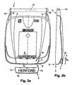
- Fig. 2a shows in plan a container 1, the primary in this view visible cover 3 has rearward protruding struts 16, by their free Ends through the axis 15 for pivoting the lid 3 relative to the underlying container 1 runs.
- Both the container 1 and the lid 3 are usually in the Injection molding process made of plastic.
- the top of the cover 3 carries permanent, in the manufacture with already introduced markings such as the Company name of the manufacturer, the date of manufacture, the designation of the Plastic, from which this lid 3 or the entire container is made etc. These primary details do not have to be changed later, and are also regardless of the future owner or operator of the container and the type of waste etc. to be placed later in the container
- the molded part 4 is a top view trapezoidal plate or plaque made of plastic on the top of the Cover 3 in its front area in a form-fitting manner Recording area 17 can be snapped on.
- the molded part 4 is 4 in different colors available, and especially from a plastic sprayed different colors, and thus colored through.
- the plaque-shaped molded part 4 can have a printed lettering, preferably embossed, which the owner, operator and / or the disposal area, such as the corresponding municipality, features.
- FIG. 2b shows the cover 3 and the molded part 4 of FIG. 2a in a side view in a sectional view.
- the existing container 1 below the lid 3 not shown for reasons of clarity.
- the cover is hood-shaped designed so that the downward-facing peripheral edge on a corresponding collar of the body 2 of the container can sit tight.
- a handle strip 9, which is approximately L-shaped, serves as the handle for opening the cover 3 is designed and with its short leg in the top of the Main part of the cover 3 passes, with the long leg of the L-shape approximately has a free end pointing horizontally towards the front.
- this horizontal leg of the handle bar 9 can be gripped and thus the lid 3 can be folded up.
- the molded part 4 is in the Cross section designed approximately C-shaped and dimensioned so that it over the horizontal leg of the handle 9 and inserted there by means of a positive Can be locked in place.
- the most important thing is that the Connection on the free front edge exposed to high loads between the handle 9 on the one hand and the molded part 4 on the other a very represents a reliable connection.
- this front edge 7b of the molded part 4 is itself C-shaped cranked, namely over the entire width of the plane of symmetry transverse, strip-shaped molded part 4.
- C-shaped Edge 7b becomes the molded part 4 from the front approximately horizontally over the front free Edge of the handle bar 9 pushed.
- the positive connection of the rear Edge 7a of the molded part 4 takes place in that with respect to the main plane of the molded part 4 downward, pointing towards the body 2 of the container 1 Leg that corresponds to the intermediate angle of the L-shaped handle bar 9th is cranked, has inwardly facing latching hooks 5 ', preferably three such locking hooks 5 'distributed over the width of this rear edge 7a.
- the free end edge is sufficient of the cranked leg of the molded part 4, which is also on the The entire width of the molded part 4 extends to the top of the Main part of the lid 3 so that here is not a sufficient distance to Attach a screwdriver etc. as a lifting tool. Becomes if this is attempted, only one of the three locking hooks can be used 5 'can be raised while the other two are still locked in place the rule to cancel this locking hook 5 leads, since only the simultaneous Lifting all locking hooks 5 'for a non-destructive removal of the Molding 4 is used.
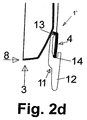
- FIG. 2d which in cross section consists of a C-shaped pressure part, whereby a tip 13 is present at the free end of one, longer leg, the presses against the inner surface of the locking hook 5 'when the bottom of the groove of the C-shaped Special tool attached to the free front edge of the handle bar 9 and rotated around the point of contact between the two parts as pivot point 14 becomes.
- This rotation is facilitated by the C-shaped body of the Special tool from the rear protrudes a lever 12 to a sufficient To allow pressure force with the tip 13 against the locking hook 5 '.
- the special tool is designed in such a way that it can be viewed across all existing snap hooks 5 'extends, and thus all existing snap hooks 5' can be pushed out of their catch at the same time.
- the molded part 4 can be approximately horizontally forward the handle bar 9 are removed.
- the molded part 4 can also be removed from container 1 possible without damaging the molded part. Because of Attaching or removing the molded part 4 also on the container, in this case on Cover 3, no irreversible changes or damage made a neutral container 1 can be changing molded parts 4 are equipped, and one and the same molded part 4 can be used in succession on different neutral containers 1 to be brought.
- the molded part 4 has no latching hooks on the lateral edges 7c, 7d but the C-shaped cross-sectional contour of the molded part 4 runs on it Free edges.
- this side edges 7c, 7d of the Molding 4 in the top of the handle 9 to a paragraph 10 the at least corresponds to the thickness of the molded part 4, so that the molded part 4 in the assembled Condition not upwards over the immediately adjacent contour protrudes from the lid.
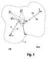
- Fig. 1 shows a basic representation of the procedure for equipping a Disposal area with the optically distinguishable containers 1 '.
- the location of the disposal company E is within the disposal area G, while the manufacturers for the molded part Hft or the neutral container Hnb, which are mostly identical to each other, usually outside the Disposal area G are located.
- the disposal company is usually at its location for both the molded parts as well also maintain corresponding bearings Lft, Lnb for the neutral containers in order to maintain the Fitting points A1, ... at short notice with the desired variant of an optical distinguishable container 1 '.
- a quick response is less necessary for the initial equipment of a disposal area than rather, if there is an additional requirement at a specific collection point A1, ..., or if due to damage to one of the containers 1 ', replacement is required is, or if at one or more of the collection points because of changed Garbage a rededication of one of the optically distinguishable containers 1 'in a different version is necessary, i.e. the equipment with another Molding 4, 4 ', ...
- contact points A1 - A3 shows that from the corresponding bearings Lft and Lnb the desired molded parts 4 and the necessary number of neutral containers 1 removed and not yet combined state are brought to the individual collection points A3, A1, A2, which can be done in a joint tour (A3, A1, A2).
- First the respective point of occurrence is the on site on a neutral container 1 corresponding molding 4 or 4 'or 4 "attached.
- the example of the point of origin Ax is the alternative procedure for this specified, namely at the point of view E of the disposal company, who usually deals with the Store Lft and Lnb for the molded parts and the neutral container is identical a neutral container 1 to fix the desired molding 4 and the thus optically distinguishable container 1 'from the disposal company E to the point of occurrence Ax spend.
- the bearings for molded parts Lft and for neutral containers Lnb are made by relevant manufacturers, i.e. from outside the disposal area, supplied and kept filled.
- the example of the accruing point A5 is the rededication of an existing one there distinguishable container 1 ':
- the desired new molded part 4' is from the warehouse for molded parts Lft to the collection point A5
- Container 1 'dismantled existing molded part 4 the new molded part 4' assembled and the old molding 4 no longer required back from the accumulation point 5 Lft in the warehouse for molded parts.
- the example of the point of origin A4 is the replacement of a damaged container 1 'shown, in which only the neutral container 1 is damaged. To this end will be a new neutral container 1a from the corresponding warehouse for neutral Container Lnb brought to the appropriate collection point A4. There is the Disassembly of the molded part z. B. 4 from the damaged neutral container 1b and the subsequent assembly of this molded part on the new neutral container 1a, and the return transport of the damaged neutral container 1b to the warehouse Lnb, where this is either repaired or scrapped.
Landscapes
- Engineering & Computer Science (AREA)
- Mechanical Engineering (AREA)
- Refuse Receptacles (AREA)
- Details Of Rigid Or Semi-Rigid Containers (AREA)
- Rigid Containers With Two Or More Constituent Elements (AREA)
- General Details Of Gearings (AREA)
- Table Devices Or Equipment (AREA)
- Auxiliary Devices For And Details Of Packaging Control (AREA)
- Making Paper Articles (AREA)
- Details Of Indoor Wiring (AREA)
- Apparatus Associated With Microorganisms And Enzymes (AREA)
- Containers Having Bodies Formed In One Piece (AREA)
Description
- unterschiedliche Farben für unterschiedliche Müllarten, wobei in der entsprechenden Farbe entweder der gesamte Behälter, also Korpus und Deckel, oder nur der Deckel, oder nur Teile des Behälters, ausgebildet sind. Dabei ist es bekannt, einen Teil des Korpus bzw. des Deckels durch Aufkleben einer Farbfolie zu kennzeichnen;
- Angabe des Eigentümers durch Einprägen eines Namensstempels mittels nachträglicher Heißprägung oder ursprünglichem Mitprägen beim Herstellen z. B. des Deckels.
- Beim Durchfärben ganzer Bauteile des Behälters bereits bei der Herstellung müssen relativ große Bauteile unterschiedlicher Farbe, z. B. unterschiedlich gefärbte Deckel, in ausreichender Anzahl bevorratet werden. Zusätzlich ergibt dies bei der Herstellung der Deckel geringere Chargengrößen und damit höhere Stückkosten.
- Beim optischen Kennzeichnen mittels Heißprägung oder Bedruckung können diese Kennzeichnungen später nicht mehr rückgängig gemacht werden, so daß eine Umwidmung des entsprechenden Behälters nicht mehr möglich ist. Gleiches gilt für aufgeklebte bzw. eingeklebte Unterscheidungsmerkmale.
- Weiterhin muß berücksichtigt werden, daß die entsprechende Kennzeichnung schnell, kostengünstig und unproblematisch und insbesondere ortsunabhängig durchzuführen sein soll, um den Kennzeichnungsaufwand niedrig zu halten.
- Fig. 1:
- eine räumliche Prinzipdarstellung des Entsorgungsgebietes,
- Fig. 2a:
- eine Aufsicht auf einen erfindungsgemäßen Müllbehälter,
- Fig. 2b:
- eine teilgeschnittene Seitenansicht des Deckels 3 der Fig. 2a, geschnitten anhand der Mittellinie der Fig. 2a, jeweils mit separatem Formteil 4,
- Fig. 2c:
- eine vergrößerte Detaildarstellung aus Fig. 2b, und
- Fig. 2d:
- eine Darstellung analog Fig. 2b, mit am Deckel 3 befestigtem Formteil 4.
- 1, 1'
- Behälter
- 2
- Korpus
- 3
- Deckel
- 4
- Formteil
- 5
- Rasthaken
- 6
- Rastnase
- 7a, 7b
- Kante
- 8
- Vorderkante
- 9
- Griffleiste
- 10
- Absatz
- 11
- Spezialwerkzeug
- 12
- Hebel
- 13
- Spitze
- 14
- Drehpunkt
- 15
- Achse
- 16
- Streben
- 17
- Aufnahmebereich
- G
- Entsorgungsgebiet
- E
- Entsorger
- A1, ...
- Anfallstelle
- -
- Demontage Formteil
- +
- Montage Formteil
- L
- Lager
- FT
- Formteil
- B
- neutrale Behälter
Claims (15)
- Verfahren zur Herstellung eines optisch nach wenigstens einem Parameter unterscheidbaren Behälters (1'), insbesondere Müllbehälters, mittelsHerstellung eines optisch neutralen, funktionsfähigen Behälters (1),lösbares Anbringen wenigstens eines optisch unterscheidbaren, im Querschnitt C-förmigen Formteiles (4) an der Außenseite des Behälters (1), wobei gekröpfte, gegenüberliegende Kanten (7a, 7b) des Formteiles (4) als Rasthaken (5, 5') dienen,ohne Vorbearbeitung des neutralen Behälters (1) für das Anbringen undohne Veränderung des neutralen Behälters (1) durch den Anbringungsvorgang.
- Verfahren zum Umwidmen eines optisch nach wenigstens einem Parameter unterscheidbaren Behälters (1'), insbesondere Müllbehälters, welcher aus einem neutralen, funktionsfähigen Behälter (1) und einem daran lösbar befestigten, optisch unterscheidbaren, im Querschnitt C-förmigen, ersten Formteil (4) besteht, dessen gekröpfte, gegenüberliegende Kanten (7a, 7b) als Rasthaken (5, 5') dienen, durchEntfernen des ersten Formteiles (4) vom neutralen Behälter (1) ohne Veränderung des neutralen Behälters (1) durch einen Entfemungsvorgang,lösbares Anbringen eines zweiten Formteiles (4') an der gleichen Stelle des neutralen Behälters (1), wobei das zweite Formteil (4') ein von dem ersten Formteil (4) optisch unterscheidbares, im Querschnitt C-förmiges Formteil (4') ist, dessen gekröpfte, gegenüberliegende Kanten als Rasthaken dienen,ohne Vorbearbeitung des neutralen Behälters (1) zwischen dem Entfernen des ersten Formteiles (4) und dem Anbringen des zweiten Formteiles (4').
- Verfahren zur Ausstattung der Anfallstellen (A1 - Ax) eines Entsorgungsgebietes (G) mit optisch nach wenigstens einem Parameter unterscheidbaren Müllbehältern (1') durch einen Entsorger (E) mittelsgetrennter Anlieferung und Bevorratung von neutralen Behältern (1) und Formteilen (4, 4', 4") in das Lager (L) des Entsorgers (E), welches insbesondere im Entsorgungsgebiet (G) liegt, undAnordnung des gewünschten Formteiles (4, 4') an den neutralen Behältern (1) beim Entsorger, so daß ein nach dem Verfahren gemäß Anspruch 1 hergestellter Behälter entsteht,Verbringen der optisch unterscheidbaren Behälter (1') vom Entsorger (E) zu der bzw. den Anlaufstellen (A1, A2, ...).
- Verfahren zur Ausstattung der Anfallstellen (A1 - Ax) eines Entsorgungsgebietes (G) mit optisch nach wenigstens einem Parameter unterscheidbaren Müllbehältern (1') durch einen Entsorger (E) mittelsgetrennter Anlieferung und Bevorratung von neutralen Behältern (1) und Formteilen (4, 4', 4") in das Lager (L) des Entsorgers (E), welches insbesondere im Entsorgungsgebiet (G) liegt,getrenntes Verbringen der neutralen Behälter (1) sowie der Formteile (4, 4', ...) vom Entsorger zu den Anfallstellen (A1, A2, ...), undAusstattung des neutralen Behälters (1) mit dem benötigten Formteil (4) bzw. (4', ...) an der jeweiligen Anfallstelle (A1, A2, ...), so daß ein nach dem Verfahren gemäß Anspruch 1 hergestellter Behälter entsteht.
- Verfahren nach einem der vorhergehenden Ansprüche, dadurch gekennzeichnet, daß das Anbringen des Formteiles (4) mittels eines Spezialwerkzeuges erfolgt, und insbesondere das beschädigungsfreie Lösen des Formteiles (4) nur mittels eines Spezialwerkzeuges möglich ist.
- Verfahren nach einem der vorhergehenden Ansprüche, dadurch gekennzeichnet, daß durch das Anbringen das Formteil (4) nicht irreversibel verändert wird, und insbesondere das Anbringen mittels Formschluß durch Verrastung erfolgt.
- Formhaltiger Behälter, insbesondere Müllbehälter, mit einem topfförmigen Korpus (2) und einem den Korpus (2) verschließenden, öffenbaren Deckel (3), wobei auf der Außenseite des Behälters (1) ein Formteil (4) lösbar formschlüssig durch Verrastung befestigt ist und insbesondere der Deckel (3) am Korpus (2) unverlierbar angeordnet ist,
dadurch gekennzeichnet, daß
das Formteil (4) im Querschnitt C-förmig ausgebildet ist und die gekröpften, gegenüberliegenden Kanten (7a, 7b) des Formteiles (4) als Rasthaken (5, 5') dienen. - Behälter nach Anspruch 7, dadurch gekennzeichnet, daß das Formteil (4) einen Anteil von wenigstens 3%, insbesondere wenigstens 5% derjenigen Seitenfläche bzw. Deckelfläche des Behälters (1) bzw. Deckels (3), auf welchem das Formteil befestigt ist, überspannt und insbesondere das Formteil (4) auf der Oberseite des Deckels (3) angeordnet ist.
- Behälter nach einem der Ansprüche 7 oder 8, dadurch gekennzeichnet, daß das Formteil (4) im Bereich der Vorderkante (8) des Deckels (3), insbesondere der Griffleiste (9) des Deckels (3), angeordnet ist und der Deckel (3) insbesondere an seiner Hinterkante am Korpus (2) angelenkt ist.
- Behälter nach einem der Ansprüche 7 bis 9, dadurch gekennzeichnet, daß die Rasthaken (5, 5') des Formteiles (4) eine große Längserstreckung entlang der Kanten des Formteiles aufweisen und insbesondere je zwei gegenüberliegende Kanten (7a, 7b) über ihre gesamte Länge wie zwei Rasthaken (5, 5') ausgebildet sind.
- Behälter nach einem der Ansprüche 7 bis 10, dadurch gekennzeichnet, daß zweimal je zwei gegenüberliegende Kanten (7a, 7b) über ihre gesamte Länge wie zwei Rasthaken (5, 5') ausgebildet sind.
- Behälter nach einem der Ansprüche 7 bis 11, dadurch gekennzeichnet, daß wenigstens die nicht als Rasthaken (5) ausgebildeten Kanten (7c, 7d) des Formteiles (4) in einem Absatz (10) des Behälters (1) positioniert sind.
- Behälter nach Anspruch 12, dadurch gekennzeichnet, daß die nicht als Rasthaken (5) ausgebildeten Kanten (7c, 7d) des Formteiles (4) nicht über die Außenkontur des Absatzes (10) vorspringen.
- Behälter nach einem der Ansprüche 7 bis 13, dadurch gekennzeichnet, daß die Außenkontur des Formteiles (4) bündig in die angrenzende Außenkontur des Behälters (1), insbesondere dessen Deckel (3), übergeht.
- Behälter nach einem der Ansprüche 7 bis 14, dadurch gekennzeichnet, daß das Formteil (4) mit seiner über die gesamte Breite ausgebildeten C-förmigen vorderen Kante (7b) die frei endende Vorderkante (8') der Griffleiste (9) umgreift.
Applications Claiming Priority (2)
| Application Number | Priority Date | Filing Date | Title |
|---|---|---|---|
| DE19820487A DE19820487C2 (de) | 1998-05-07 | 1998-05-07 | Aufrastbare Kennzeichnungsplakette |
| DE19820487 | 1998-05-07 |
Publications (2)
| Publication Number | Publication Date |
|---|---|
| EP0955250A1 EP0955250A1 (de) | 1999-11-10 |
| EP0955250B1 true EP0955250B1 (de) | 2003-03-19 |
Family
ID=7867010
Family Applications (1)
| Application Number | Title | Priority Date | Filing Date |
|---|---|---|---|
| EP99109108A Expired - Lifetime EP0955250B1 (de) | 1998-05-07 | 1999-05-07 | Behälter mit aufrastbarer Kennzeichnungsplakette sowie Herstellungsverfahren |
Country Status (6)
| Country | Link |
|---|---|
| EP (1) | EP0955250B1 (de) |
| AT (1) | ATE234778T1 (de) |
| DE (2) | DE19820487C2 (de) |
| DK (1) | DK0955250T3 (de) |
| ES (1) | ES2192812T3 (de) |
| PT (1) | PT955250E (de) |
Cited By (1)
| Publication number | Priority date | Publication date | Assignee | Title |
|---|---|---|---|---|
| DE202014102080U1 (de) | 2014-05-05 | 2014-10-23 | Fritz Schäfer GmbH | Mülltonnen mit austauschbarem Deckeleinsatz |
Families Citing this family (2)
| Publication number | Priority date | Publication date | Assignee | Title |
|---|---|---|---|---|
| PL4282783T3 (pl) * | 2022-05-25 | 2026-01-26 | Ese World B.V. | Elementy wskaźnikowe do pojemników do zbiórki odpadów |
| CN118289358B (zh) * | 2024-03-26 | 2024-09-03 | 江苏荣生电子有限公司 | 一种电极箔废弃物收集装置 |
Family Cites Families (5)
| Publication number | Priority date | Publication date | Assignee | Title |
|---|---|---|---|---|
| DE8501525U1 (de) * | 1985-05-02 | Gawepa Gartenbauverlag für Werbung und Verpackung GmbH, 4950 Minden | Auszeichnungsschild für Waren | |
| DE8125177U1 (de) * | 1981-08-28 | 1982-04-15 | Bitsch, Barthel, 6145 Lindenfels | Muelltonne |
| DE4226253A1 (de) * | 1992-08-08 | 1994-02-10 | Loebbert Franz Josef | Abdeckung für Abfalltonnen/Abfallcontainer |
| DE9317805U1 (de) * | 1993-11-22 | 1995-03-23 | Kloiber, Martina, 83714 Miesbach | Vorrichtung zur Kennzeichnung und/oder Beschriftung von Gegenständen |
| DE29515775U1 (de) * | 1995-10-05 | 1995-12-07 | Engelbrecht, Frank, 58579 Schalksmühle | Vorrichtung zur Anordnung von Gebührenmarken an Müllbehältern |
-
1998
- 1998-05-07 DE DE19820487A patent/DE19820487C2/de not_active Expired - Fee Related
-
1999
- 1999-05-07 DK DK99109108T patent/DK0955250T3/da active
- 1999-05-07 EP EP99109108A patent/EP0955250B1/de not_active Expired - Lifetime
- 1999-05-07 AT AT99109108T patent/ATE234778T1/de active
- 1999-05-07 DE DE59904587T patent/DE59904587D1/de not_active Expired - Lifetime
- 1999-05-07 ES ES99109108T patent/ES2192812T3/es not_active Expired - Lifetime
- 1999-05-07 PT PT99109108T patent/PT955250E/pt unknown
Cited By (1)
| Publication number | Priority date | Publication date | Assignee | Title |
|---|---|---|---|---|
| DE202014102080U1 (de) | 2014-05-05 | 2014-10-23 | Fritz Schäfer GmbH | Mülltonnen mit austauschbarem Deckeleinsatz |
Also Published As
| Publication number | Publication date |
|---|---|
| DK0955250T3 (da) | 2003-06-23 |
| PT955250E (pt) | 2003-08-29 |
| ATE234778T1 (de) | 2003-04-15 |
| EP0955250A1 (de) | 1999-11-10 |
| ES2192812T3 (es) | 2003-10-16 |
| DE19820487A1 (de) | 1999-11-18 |
| DE59904587D1 (de) | 2003-04-24 |
| DE19820487C2 (de) | 2001-11-08 |
Similar Documents
| Publication | Publication Date | Title |
|---|---|---|
| EP0252319A1 (de) | Messer mit einem im wesentlichen hohlen Griffkörper | |
| EP0907469A1 (de) | Aufbewahrungsvorrichtung für schraubendreherbits oder dergleichen und zugehörigem futter | |
| DE3026930A1 (de) | Keilanordnung und zugeordnete mittel fuer befestigungsvorrichtungen, traeger und meissel und derenkombinationen fuer den bergbau, strassenbau und erdbewegungsmaschinen | |
| EP0039803A1 (de) | Handetikettiergerät | |
| EP0499973A1 (de) | Zangendosenöffner | |
| DE69811522T2 (de) | Dentifikationsvorrichtung für behälter | |
| DE69716562T2 (de) | Bürste und Verfahren zu deren Herstellung | |
| DE19820487C2 (de) | Aufrastbare Kennzeichnungsplakette | |
| DE69405534T2 (de) | Universalhalter für die Seitenführung eines Rolladens | |
| DE19616741B4 (de) | Verbesserungen der Werbemöglichkeiten an Rolltreppen | |
| EP0180146B1 (de) | Stanze | |
| EP0280877A1 (de) | Handetikettiergerät | |
| DE1934449B2 (de) | Austauschbares, selbstschmierendes Schwenkgleitlager, insbesondere für unter Staub- und Schmutzbedingungen einsetzbare Arbeitsgeräte, wie Erdbewegungsmaschinen | |
| DE4106773B4 (de) | Brennelementbündel für einen Kernreaktor | |
| DE2303009A1 (de) | Druckvorrichtung | |
| DE69507061T2 (de) | Dose mit Deckel und Verschlussring | |
| DE3515610C1 (de) | Andrueckrolle fuer ein Etikettiergeraet | |
| DE2020644A1 (de) | Siegelpresse | |
| DE2636767A1 (de) | Einschlaggehaeuse fuer moebelscharniere | |
| DE19615280A1 (de) | Verfahren zum Spritzgießen eines Formkörpers aus Kunststoff | |
| DE9213605U1 (de) | Druckmaschinenzylinder-Waschvorrichtung | |
| EP0292753A1 (de) | Feuersicheres Kennzeichnungsschild | |
| DE20017211U1 (de) | Behälter aus Kunststoff mit einem Deckel | |
| DE9311953U1 (de) | Vorrichtung zum Anbringen von Verbindungs- oder Befestigungselementen an einem Trägermaterial, insbesondere aus faserverstärktem Kunststoff | |
| DE9301147U1 (de) | Vorrichtung zur Versorgung eines Farbverbrauchers mit unterschiedlichen Farben |
Legal Events
| Date | Code | Title | Description |
|---|---|---|---|
| PUAI | Public reference made under article 153(3) epc to a published international application that has entered the european phase |
Free format text: ORIGINAL CODE: 0009012 |
|
| AK | Designated contracting states |
Kind code of ref document: A1 Designated state(s): AT DE DK ES FR GB GR IT NL PT SE |
|
| AX | Request for extension of the european patent |
Free format text: AL;LT;LV;MK;RO;SI |
|
| 17P | Request for examination filed |
Effective date: 20000218 |
|
| AKX | Designation fees paid |
Free format text: AT DE DK ES FR GB GR IT NL PT SE |
|
| 17Q | First examination report despatched |
Effective date: 20010418 |
|
| RTI1 | Title (correction) |
Free format text: CONTAINER WITH A SNAP-ON MARKING PLATE AND PROCESS FOR MAKING THE SAME |
|
| GRAH | Despatch of communication of intention to grant a patent |
Free format text: ORIGINAL CODE: EPIDOS IGRA |
|
| GRAH | Despatch of communication of intention to grant a patent |
Free format text: ORIGINAL CODE: EPIDOS IGRA |
|
| GRAA | (expected) grant |
Free format text: ORIGINAL CODE: 0009210 |
|
| AK | Designated contracting states |
Designated state(s): AT DE DK ES FR GB GR IT NL PT SE |
|
| REG | Reference to a national code |
Ref country code: GB Ref legal event code: FG4D Free format text: NOT ENGLISH |
|
| REF | Corresponds to: |
Ref document number: 59904587 Country of ref document: DE Date of ref document: 20030424 Kind code of ref document: P |
|
| REG | Reference to a national code |
Ref country code: DK Ref legal event code: T3 |
|
| GBT | Gb: translation of ep patent filed (gb section 77(6)(a)/1977) | ||
| REG | Reference to a national code |
Ref country code: SE Ref legal event code: TRGR |
|
| REG | Reference to a national code |
Ref country code: GR Ref legal event code: EP Ref document number: 20030402210 Country of ref document: GR |
|
| ET | Fr: translation filed | ||
| REG | Reference to a national code |
Ref country code: ES Ref legal event code: FG2A Ref document number: 2192812 Country of ref document: ES Kind code of ref document: T3 |
|
| PLBE | No opposition filed within time limit |
Free format text: ORIGINAL CODE: 0009261 |
|
| STAA | Information on the status of an ep patent application or granted ep patent |
Free format text: STATUS: NO OPPOSITION FILED WITHIN TIME LIMIT |
|
| 26N | No opposition filed |
Effective date: 20031222 |
|
| PGFP | Annual fee paid to national office [announced via postgrant information from national office to epo] |
Ref country code: DK Payment date: 20150529 Year of fee payment: 17 Ref country code: ES Payment date: 20150626 Year of fee payment: 17 Ref country code: PT Payment date: 20150611 Year of fee payment: 17 |
|
| PGFP | Annual fee paid to national office [announced via postgrant information from national office to epo] |
Ref country code: GR Payment date: 20150529 Year of fee payment: 17 Ref country code: IT Payment date: 20150529 Year of fee payment: 17 Ref country code: AT Payment date: 20150601 Year of fee payment: 17 |
|
| REG | Reference to a national code |
Ref country code: FR Ref legal event code: PLFP Year of fee payment: 18 |
|
| PGFP | Annual fee paid to national office [announced via postgrant information from national office to epo] |
Ref country code: NL Payment date: 20160530 Year of fee payment: 18 |
|
| PGFP | Annual fee paid to national office [announced via postgrant information from national office to epo] |
Ref country code: DE Payment date: 20160530 Year of fee payment: 18 Ref country code: GB Payment date: 20160531 Year of fee payment: 18 |
|
| PGFP | Annual fee paid to national office [announced via postgrant information from national office to epo] |
Ref country code: SE Payment date: 20160530 Year of fee payment: 18 Ref country code: FR Payment date: 20160525 Year of fee payment: 18 |
|
| REG | Reference to a national code |
Ref country code: DK Ref legal event code: EBP Effective date: 20160531 |
|
| REG | Reference to a national code |
Ref country code: AT Ref legal event code: MM01 Ref document number: 234778 Country of ref document: AT Kind code of ref document: T Effective date: 20160507 |
|
| REG | Reference to a national code |
Ref country code: GR Ref legal event code: ML Ref document number: 20030402210 Country of ref document: GR Effective date: 20161207 |
|
| PG25 | Lapsed in a contracting state [announced via postgrant information from national office to epo] |
Ref country code: GR Free format text: LAPSE BECAUSE OF NON-PAYMENT OF DUE FEES Effective date: 20161207 Ref country code: PT Free format text: LAPSE BECAUSE OF NON-PAYMENT OF DUE FEES Effective date: 20161107 Ref country code: IT Free format text: LAPSE BECAUSE OF NON-PAYMENT OF DUE FEES Effective date: 20160507 Ref country code: AT Free format text: LAPSE BECAUSE OF NON-PAYMENT OF DUE FEES Effective date: 20160507 |
|
| PG25 | Lapsed in a contracting state [announced via postgrant information from national office to epo] |
Ref country code: DK Free format text: LAPSE BECAUSE OF NON-PAYMENT OF DUE FEES Effective date: 20160531 |
|
| REG | Reference to a national code |
Ref country code: DE Ref legal event code: R119 Ref document number: 59904587 Country of ref document: DE |
|
| REG | Reference to a national code |
Ref country code: SE Ref legal event code: EUG |
|
| REG | Reference to a national code |
Ref country code: NL Ref legal event code: MM Effective date: 20170601 |
|
| GBPC | Gb: european patent ceased through non-payment of renewal fee |
Effective date: 20170507 |
|
| PG25 | Lapsed in a contracting state [announced via postgrant information from national office to epo] |
Ref country code: SE Free format text: LAPSE BECAUSE OF NON-PAYMENT OF DUE FEES Effective date: 20170508 |
|
| REG | Reference to a national code |
Ref country code: FR Ref legal event code: ST Effective date: 20180131 |
|
| PG25 | Lapsed in a contracting state [announced via postgrant information from national office to epo] |
Ref country code: NL Free format text: LAPSE BECAUSE OF NON-PAYMENT OF DUE FEES Effective date: 20170601 |
|
| PG25 | Lapsed in a contracting state [announced via postgrant information from national office to epo] |
Ref country code: DE Free format text: LAPSE BECAUSE OF NON-PAYMENT OF DUE FEES Effective date: 20171201 Ref country code: GB Free format text: LAPSE BECAUSE OF NON-PAYMENT OF DUE FEES Effective date: 20170507 |
|
| PG25 | Lapsed in a contracting state [announced via postgrant information from national office to epo] |
Ref country code: FR Free format text: LAPSE BECAUSE OF NON-PAYMENT OF DUE FEES Effective date: 20170531 Ref country code: ES Free format text: LAPSE BECAUSE OF NON-PAYMENT OF DUE FEES Effective date: 20160508 |
|
| REG | Reference to a national code |
Ref country code: ES Ref legal event code: FD2A Effective date: 20181128 |