EP0955175A2 - Den Unregelmässigkeiten der Druckwagengeschindigkeit angepasstes Drucken - Google Patents
Den Unregelmässigkeiten der Druckwagengeschindigkeit angepasstes Drucken Download PDFInfo
- Publication number
- EP0955175A2 EP0955175A2 EP99303425A EP99303425A EP0955175A2 EP 0955175 A2 EP0955175 A2 EP 0955175A2 EP 99303425 A EP99303425 A EP 99303425A EP 99303425 A EP99303425 A EP 99303425A EP 0955175 A2 EP0955175 A2 EP 0955175A2
- Authority
- EP
- European Patent Office
- Prior art keywords
- print data
- scan
- speed
- printing
- Prior art date
- Legal status (The legal status is an assumption and is not a legal conclusion. Google has not performed a legal analysis and makes no representation as to the accuracy of the status listed.)
- Granted
Links
- 238000000034 method Methods 0.000 claims description 44
- 230000015556 catabolic process Effects 0.000 claims description 18
- 238000006731 degradation reaction Methods 0.000 claims description 18
- 230000033001 locomotion Effects 0.000 claims description 10
- 230000002411 adverse Effects 0.000 description 6
- 230000003247 decreasing effect Effects 0.000 description 5
- 230000007175 bidirectional communication Effects 0.000 description 4
- 238000010586 diagram Methods 0.000 description 4
- 238000012545 processing Methods 0.000 description 4
- 230000000694 effects Effects 0.000 description 3
- 230000009977 dual effect Effects 0.000 description 2
- 230000015572 biosynthetic process Effects 0.000 description 1
- 230000006854 communication Effects 0.000 description 1
- 238000004891 communication Methods 0.000 description 1
- 230000005055 memory storage Effects 0.000 description 1
- 238000012986 modification Methods 0.000 description 1
- 230000004048 modification Effects 0.000 description 1
- 238000012360 testing method Methods 0.000 description 1
Images


Classifications
-
- B—PERFORMING OPERATIONS; TRANSPORTING
- B41—PRINTING; LINING MACHINES; TYPEWRITERS; STAMPS
- B41J—TYPEWRITERS; SELECTIVE PRINTING MECHANISMS, i.e. MECHANISMS PRINTING OTHERWISE THAN FROM A FORME; CORRECTION OF TYPOGRAPHICAL ERRORS
- B41J19/00—Character- or line-spacing mechanisms
- B41J19/18—Character-spacing or back-spacing mechanisms; Carriage return or release devices therefor
- B41J19/20—Positive-feed character-spacing mechanisms
- B41J19/202—Drive control means for carriage movement
Definitions
- the present invention relates to a printer which prints using a print head mounted on a movable carriage, such as an ink jet printer, which prints through uni-directional or reciprocal back and forth motions of its print head carriage. More particularly, the invention relates to such a printer in which carriage speed non-uniformities are accommodated by determining print direction and print speed based on printed data content, paper size and the like.
- Printers such as ink jet printers have become an extremely popular format for achieving high quality computer print out at low cost. These printers form a printed image through movement of a movable carriage, on which a print head is mounted, in reciprocal uni-directional or left and right printing passes at high scanning speeds across the width of a recording medium, while the recording medium is slowly fed in the lengthwise direction.
- the printed image is formed by ejecting small ink droplets from the print head in predetermined patterns on to the recording medium.
- FIG. 1 is a graphical representation of carriage speed 12 as the carriage commences movement from a standstill position at 14 to a target scanning speed 15 across the width of a recording medium.
- speed in carriage 11 exhibits ringing and overshoot indicated generally at 16.
- print head A commences print out at the position indicated by "a"
- print head B will not reach position "a” until the carriage has continued movement to the position indicated in phantom lines. At that position, ringing, overshoot and other carriage non-uniformities have decreased greatly. Accordingly, print quality from print head B will be affected by carriage speed non-uniformities only to the extent of that indicated at ⁇ B. Since ⁇ A and ⁇ B are different, it will be appreciated that print quality will be affected differently for print head A and print head B. Thus, in a case where print out by print head A is desired to be superimposed over print out by print head B, accuracy of the superimposition will be degraded, since at the same print position, print head A will be printing at a slightly different speed than print head B.
- FIG. 2 Another problem caused by carriage speed non-uniformities is illustrated in Figure 2, and involves coordination of forward and reverse printing.
- a recording medium 20 on which it is desired print a first band of print data in area 21 in a forward direction, followed by a second band of print data in a reverse direction in band 22.
- 24 indicates overshoot and ringing in carriage speed in the forward direction of printing
- 25 indicates carriage speed overshoot and ringing while printing in the reverse direction.
- carriage speed matches only in the central region 26 in each of bands 21 and 22.
- An aspect of the invention provides for a judgment of printing direction and/or printing speed based on content of print data, recording medium width, and the like.
- the subsequent scan included print data only in a central area of the recording medium, then print quality would not be adversely affected by non-uniformities in carriage speed. Accordingly, reverse printing of the subsequent scan would be effected. Thereafter, printing for a next subsequent scan could be effected in either of the forward or reverse directions, regardless of the content of the print data, since the now-previous scan occupies only a central area of the recording medium indicating that carriage non-uniformities would not adversely affect print quality of the next subsequent scan.
- print out were being effected on a narrow-width recording medium, occupying only a central area of carriage scanning, then printing could be effected in either a forward or reverse direction without adversely affecting print quality due to carriage speed non-uniformities.
- the invention slows the overall carriage printing speed for individual ones of printing scans, so as to lower the adverse effect of carriage speed non-uniformities. Specifically, at slowed carriage scanning speeds, the size of ringing and overshoot non-uniformities are reduced significantly. Accordingly, even though one or two printing scans on a recording medium might have been performed slowly, overall printing efficiency is increased since other scans can be printed in forward and reverse directions, without adversely affecting print quality due to carriage speed non-uniformities. Accordingly, overall printing efficiency is increased.
- Figures 1 and 2 are views for explaining ramp-up non-uniformities in carriage printing speed.
- Figure 3 is a perspective view of computing equipment and a printer used in connection with the present invention.
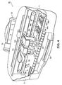
- Figure 4 is cut-away front perspective view of the printer of Figure 3 showing multiple print heads.
- FIG. 5 is a detailed block diagram showing the hardware configuration of computing equipment interfaced to the printer of Figure 3.
- Figures 6 and 7 are views for explaining printing control according to a first embodiment of the invention.
- Figures 8 and 9 are views for explaining printing control according to a second embodiment of the invention.
- FIG. 3 is a view showing the outward appearance of computing equipment 80 and a printer 50 used in connection with the practice of the present invention.
- Computing equipment 40 includes host processor 41 which comprises a personal computer (hereinafter "PC"), preferably an IBM PC-compatible computer having a windowing environment such as Microsoft Windows 95.
- host processor 41 which comprises a personal computer (hereinafter "PC"), preferably an IBM PC-compatible computer having a windowing environment such as Microsoft Windows 95.
- display 43 including display screen 42, keyboard 46 for entering text data and user commands, and pointing device 47.
- Pointing device 47 preferably comprises a mouse for pointing and for manipulating objects displayed on display screen 42.
- Computing equipment 40 includes a computer-readable memory medium such as computer disk 45 and/or floppy disk drive 44.
- Floppy disk drive 44 provides a means whereby computing equipment 40 can access information, such as data, application programs, etc. stored on removable memory media.
- a similar CD-ROM interface (not shown) may be provided for computing equipment 40 through which computing equipment 40 can access information stored on removable CD-ROM media.
- Printer 50 is preferably a color ink jet printer which forms images by ejecting droplets of ink onto a recording medium such as paper or transparencies or the like.
- a recording medium such as paper or transparencies or the like.
- One suitable printer is described in Application No. 08/972,139, "Ejection Tray For A Printer", the contents of which are incorporated herein by reference as if set forth in full.
- the invention is usable with other printers, however, so long as the printer prints using a print head mounted on a movable carriage.
- FIG. 4 is a cut-away front perspective view of printer 50.
- printer 50 includes housing 51 covered by an unshown removable cover, supply tray 52 for an automatic sheet feeder, feed width adjuster 54, ejection port 55, and slidably stowable ejection tray 56.
- An unshown manual feed slot accepts wide-format or thick recording media.
- Not shown in Figure 4 are indicator lights, power buttons, resume (on/offline) buttons, power supply and cord, and a parallel port connector for connection of printer 50 to computing equipment 40, preferably via a bi-directional communication interface.
- printer 50 includes rollers 60 for feeding media from either the automatic feeder or the manual feeder through printer 50 to media ejection port 55.
- Removable dual print heads 61a and 61b are mounted in respective receiving stations 62a and 62b which in turn are mounted at a fixed horizontal offset on carriage 63.
- Covers 64a and 64b latch print heads 61a and 61b in position at receiving stations 62a and 62b.
- Carriage 63 is mounted for reciprocal left and right scanning movements on carriage guide rod 69, and carriage 63 is reciprocally driven across guide rod 69 by belt 67 and an unshown carriage drive motor.
- Carriage 63 can be driven from an extreme leftward position indicated generally at 86, which is outside of a carriage reciprocation area during normal (standard or wide width) print operations, to an extreme rightward position indicated generally at 87, which is also outside of carriage reciprocation operation area during normal printing.
- Position 87 is also referred to as a "home" position, and includes a pair of ink ejection stations 84a and 84b, a pair of wiping blades 83a and 83b for wiping the face of the print heads to remove ink residue, and a pair of ink capping stations 88a and 88b, each for respective ones of print heads 61a and 61b.
- Hingedly mounted on carriage 63 is alignment sensor cover 75 which, during normal print operation, covers alignment sensor 82 (shown in phantom lines) which is used to align print head 61a to print head 61b. Movement of carriage 63 between the extreme left position 86 (for engagement with upstanding tab 70) and extreme right position 87 cause cover 75 to be hinged open and closed.
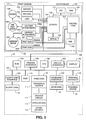
- FIG. 5 is a block diagram showing the internal structures of-computing equipment 40 and printer 50.
- computing equipment 40 includes a central processing unit (“CPU") 100 such as a programmable microprocessor interfaced to computer bus 101. Also coupled to computer bus 101 are display interface 102 for interfacing to display 43, printer interface 104 for interfacing to printer 50 through a bi-directional communication line 106, floppy disk interface 124 for interfacing to floppy disk drive 44, keyboard interface 109 for interfacing to keyboard 46, and pointing device interface 110 for interfacing to pointing device 47.
- a random access memory (“RAM”) 116 interfaces to computer bus 101 to provide CPU 100 with access to memory storage.
- RAM random access memory
- CPU 100 when executing stored program instruction sequences, loads those instruction sequences from disk 45 (or other memory media such as computer readable media accessed via an unshown network interface) into RAM 116 and executes those stored program instruction sequences out of RAM 116. It should also be recognized that standard disk-swapping techniques available under windowing operating systems allow segments of memory to be swapped on and off disk 45 to RAM 116.
- Read only memory (“ROM”) 103 in computing equipment 40 stores invariant instruction sequences, such as start-up instruction sequences or basic input/output operating system (“BOIS”) sequences for operation of keyboard 46.
- invariant instruction sequences such as start-up instruction sequences or basic input/output operating system (“BOIS") sequences for operation of keyboard 46.
- BOIS basic input/output operating system
- Disk 45 is one example of a computer readable medium that stores program instruction sequences executable by CPU 100 so as to constitute operating system 111, application programs 112, printer driver 114 and other application programs, files, and device drivers such as driver 119.
- Application programs are programs by which computing equipment 40 generates files, manipulates and stores those files on disk 45, presents data on those files to a user via display screen 42, and prints data via printer 50.
- Disk 45 also stores an operating system 111 which, as noted above, is preferably a windowing operating system.
- Device drivers are also stored on disk 45. At least one of the device drivers comprises a printer driver 114 which provides a software interface to printer 50. Data exchanged between computing equipment 40 and printer 50 is effected by the printer driver, as described in more detail below. In particular, alignment according to the invention is controlled by program instruction sequences coded by printer driver 114.
- printer 50 includes print controller 120 and print engine 131.
- Print controller 120 contains computerized and electronic devices used to control print engine 131, and print engine 131 includes physical devices such as carriage and line feed motors together with a print carriage and print heads depicted in Figure 4 for obtaining print output.
- print controller 120 includes CPU 121 such as an 8-bit or 16-bit microprocessor, ROM 122, control logic 124 and I/O ports 127 connected to bus 126. Also connected to control logic 124 is RAM 129. Connected to I/O ports 127 is EEPROM 132 for storing printer parameters, such as the width of conflict zones, which can be obtained by computing equipment 40 over bi-directional link 106 for use during subsequent printing operations.
- Print engine 131 includes line feed motor 136 controlled by line feed motor driver 136a, and carriage motor 137 controlled by carriage motor driver 137a.
- Dual print heads 61a and 61b are removable print heads carried on carriage 63 ( Figure 4) and include ink ejection nozzles for forming a printed image on a recording medium, as well as sensors to provide feedback as to the presence and characteristics of the removable print heads.
- Control logic 124 provides control signals for nozzles in print heads 61a and 61b and further provides control logic for line feed motor driver 136a and carriage motor driver 137a, via I/O port 127.
- I/O port 127 receives sensor output from print heads 61a and 61b, sensor output from sensors 134 and switches 133, and in addition provides control signals for buzzer 128 and LEDs 135.
- I/O ports 127 channel control signals from control logic 124 to line feed motor driver 136a and carriage motor driver 137a.
- ROM 122 stores font data, program instruction sequences to control printer 50, and other invariant data for printer operation.
- RAM 129 stores print data in a print buffer defined by the program instruction sequences in ROM 122, for printout by print heads 61a and 61b.
- EEPROM 132 provides non-volatile reprogrammable memory for printer information such as print head configuration, print head alignment parameters, parameters that identify the printer, the printer driver, the print heads, status of ink in the ink cartridges, width of conflict zones, and the like, all of which may be provided to print driver 114 in computing equipment 40 so as to inform computing equipment 40 of operational parameters of printer 50, and so as to allow print driver 114 to change print data sent to printer 50 over bi-directional communication line 106 so as to accommodate various configurations of printer 50.
- printer information such as print head configuration, print head alignment parameters, parameters that identify the printer, the printer driver, the print heads, status of ink in the ink cartridges, width of conflict zones, and the like, all of which may be provided to print driver 114 in computing equipment 40 so as to inform computing equipment 40 of operational parameters of printer 50, and so as to allow print driver 114 to change print data sent to printer 50 over bi-directional communication line 106 so as to accommodate various configurations of printer 50.
- Figure 6 is a flow diagram illustrating computer-executable stored program instruction sequences constituting improved printing to accommodate carriage speed non-uniformities, according to one embodiment of the invention.
- the process steps shown in the left-hand side of Figure 6 are preferably stored in printer driver 114 on disk 45, and are executed by CPU 100 so as to make determinations of whether reversed printing would degrade print quality based on carriage speed non-uniformities.
- the process steps in the right-hand side of Figure 6 are preferably stored in ROM 122 for execution by CPU 121 so as to receive print data for forward or reversed printing, move carriage 63 based on commands from computing equipment 40, and print in directions commanded by computing equipment 40.
- solid lines refer to flow sequences within each of CPUs 100 and 121, whereas dashed lines refer to communication over bi-directional communication link 106.
- the stored program instruction sequences illustrated in Figure 6 comprise printing for a current scan of print data based on printing direction and lateral extent of print data for a prior scan, in which a determination is made as to whether the lateral extent of print data for a current scan would cause print quality degradation due to carriage speed non-uniformities. If, based on the lateral extent of print data for the current and prior scan, a determination is made that print quality would- be degraded by reverse printing, then print out of the current scan is effected in the same direction as that of the prior scan.
- step S601 computing equipment 40 determines the lateral extent of printed data on the recording medium for a prior scan
- step S602 computing equipment 40 determines the lateral extent of printed data for a current scan.
- step S604 a determination is made as to whether or not print out of the current scan, if made in a direction opposite to that of print out for the prior scan, would cause print quality degradation due to carriage speed non-uniformities.
- a full explanation of how conflicts might occur is given with respect to Figure 7; generally speaking, however, conflicts would occur if printed data for both the current scan and the prior scan would appear at the same time in either one of conflict zones at extreme lateral edges of the recording medium.
- step S604 determines that a conflict would occur, meaning that print data would be degraded if print out of the current scan were printed in a direction opposite to that of the prior scan
- step S605 computing equipment 40 commands printer 50 to return carriage 63 to the opposite side of the printer chassis, in preparation for print out in the same direction as that of the prior scan.
- step S621 computing equipment 40 sends print data to printer 50 for the current scan.
- step S606 the print data for the current scan is sent to printer 50 in the same order as that of the prior scan.
- step S622 After the print data has been sent and stored in printer 50 (step S622), computing equipment 40 sends a command (step S607) to printer 50 so as to effect print out of the current scan in the same direction as that of the prior scan (step S623). Thereafter, flow returns to step S601, for processing of a next subsequent scan of print data.
- step S604 determines that no conflict would be caused by reverse printing, meaning that print out of a current scan in a direction opposite to that of the prior scan would not unduly degrade print data due to carriage speed non-uniformities, then flow branches to step S609.
- step S609 computing equipment 40 sends print data for the current scan to printer 50, the print data being sent in an order opposite to that of the prior scan.
- step S625 After storage of the print data by printer 50 (step S625), computing equipment sends a command to print the current scan (step S610).
- Printer 50 responds in step S626 by printing the current scan of print data in a direction opposite to that of the prior scan. Flow then returns to step S601 for processing of a next subsequent scan.
- Figure 7 is a view for explaining situations in which step S604 would determine that there would, or would not, be a conflict for reverse printing due to carriage speed non-uniformities.
- Figure 7 depicts a recording medium 30 on which are shown plural scans 33 through 39 both in the forward direction and the reverse directions, respectively indicated by the letters "F" and "R". Shown in phantom lines and superimposed on each of scans 33 though 39 are ringing and overshoot patterns depicting carriage speed non-uniformities.
- Figure 7 also shows conflict zones 31 and 32, each arranged at extreme lateral right and left-hand sides within the printing zone of recording medium 30.
- conflict zones are sized from the edge of recording medium 30 (or from the edge of a print zone thereof), extending for a distance inwardly corresponding to the distance b-a (see Figure 1) from where print degradations due to speed non-uniformities are noticeable to where they are no longer noticeable and do not degrade print quality.
- Scan 33 proceeds in a forward direction, since it is the first scan on recording medium 30 and there is no need to make any determinations as to whether a conflict in scanning direction would occur.
- step S604 determines that there would be a conflict if print out were effected in a reverse direction.
- the conflict would occur at both conflict zones 31 and 32, since if scanning were effected in a reverse direction then print out for scan 33 and for scan 34 would not match in both of the conflict zones. Accordingly, print out for scan 34 is effected in the same direction as that for scan 33, corresponding to steps S605 through S607.
- step S604 determines that no conflict would be caused. No conflict would be caused since the lateral extent of print data for scan 35 does not extend into either of conflict zones 31 or 32 where print data for prior scan 34 is present. Accordingly, print out for scan 35 is effected in a reverse direction, corresponding to steps S609 and S610.
- step S604 determines that no conflict would be caused. No conflict would be caused since there is no overlap of print data between current scan 36 and prior scan 35 in either of conflict zones 31 or 32. Accordingly, print out for scan 36 is effected in the opposite direction to that of prior scan 35, in correspondence to steps S609 and S610.
- step S604 determines that a conflict would occur if print out were effected in an opposite direction. Accordingly, print data for scan 38 is effected in the same direction as that of prior scan 37, corresponding to steps S605 through S607.
- print out of scan 39 is effected in the same direction as that of prior scan 38.
- a second embodiment of the invention modifies that of the Figure 6 embodiment by inserting a test to determine whether a slower carriage speed would avoid a conflict if opposite direction printing were allowed.
- this second embodiment is based on the observation that for slower carriage speeds, carriage speed non-uniformities are decreased dramatically, particularly non-uniformities due to ringing and speed overshoot.
- the width of critical zones such as critical zones 31 and 32 depicted in Figure 7, can be decreased.
- step S801 computing equipment 40 determines the lateral extent of printed data on the recording medium for a prior scan
- step S802 computing equipment 40 determines the lateral extent of printed data for a current scan.
- step S804 a determination is made as to whether or not printout of the current scan, if printed at standard printing speed and if made in a direction opposite to that of printout for a prior scan, would cause print quality degradation due to carriage speed non-uniformities.
- Conflicts in step S804 are determined as shown above in connection with Figure 7, and occur if printed data for both the current scan and the prior scan would appear at the same time in either one of conflict zones 31 and 32 at lateral edges of the recording medium.
- step S804 determines that no conflict would be caused by reverse printing at the standard printing speed, meaning that printout of a current scan in a direction opposite to that of the prior scan and at a high speed would not unduly degrade print data due to carriage speed non-uniformities, then flow branches to step S809 in which carriage speed for carriage 63 is set at full speed.
- Printer 50 responds by setting the carriage speed as appropriate (step S824). Thereafter, in step S811, computing equipment 40 sends print data for the current scan to printer 50, the print data being sent in an order opposite to that of the prior scan. After storage of the print data by printer 50 (step S825), computing equipment 40 sends a command to print the current scan (step S812).
- Printer 50 responds in step S826 by printing the current scan of print data at full carriage speed in a direction opposite to that of the prior scan. Flow then returns to step S801 for processing of the next subsequent scan.
- step S804 determines that a conflict would be caused by reverse printing at full carriage speed
- step S805 determines whether the conflict would remain if the carriage speed were reduced.
- carriage speeds less than a full printing speed such as half printing speed
- carriage non-uniformities due to ringing, overshoot and the like are significantly decreased.
- the width of conflict zones 31 and 32 are reduced as shown at 31' and 32'.
- the width of the conflict zones 31' and 32' are reduced relative to the width of conflict zones 31 and 32 for full printing speeds.
- scan 39' can be printed at a slow carriage speed but in the forward direction rather than the reverse direction, thereby saving time needed to return the carriage to the opposite side and otherwise increasing overall printing efficiency.
- step S805 determines that the conflict would be removed if the carriage speed were slowed
- step S810 in which the carriage speed is set to a slow carriage speed, with printer 50 responding appropriately (step S824). Thereafter, flow proceeds to step S811 and S812, and to S825 and S826, for opposite direction printing.
- step S805 determines that the conflict would not be removed even if the carriage speed were slowed, then flow advances to steps S806 through S808 in which carriage 63 is returned to the opposite side of the printer chassis, print data is sent in the same order as that of the prior scan, and a print command is sent, all so as to cause printer 50 to print in the same direction as that of a prior scan (steps S821 through S823).
- the conflict zones might actually lie outside the lateral extent of the recording medium in a case where the recording medium is narrow and located centrally in the carriage reciprocation path.
- a third embodiment of the invention allows opposite direction printing in all instances where the recording medium is narrow and centrally located, since it is predetermined that step S604 would result in a "no-conflict" determination.
- the present invention can be embodied as software, it can downloaded over a network such as the internet.
- the present invention encompasses a signal carrying computer implementable instructions for controlling a processor.
Landscapes
- Character Spaces And Line Spaces In Printers (AREA)
- Ink Jet (AREA)
- Dot-Matrix Printers And Others (AREA)
Applications Claiming Priority (2)
| Application Number | Priority Date | Filing Date | Title |
|---|---|---|---|
| US71110 | 1998-05-04 | ||
| US09/071,110 US6373593B1 (en) | 1998-05-04 | 1998-05-04 | Printer which accommodates carriage speed non-uniformities |
Publications (3)
| Publication Number | Publication Date |
|---|---|
| EP0955175A2 true EP0955175A2 (de) | 1999-11-10 |
| EP0955175A3 EP0955175A3 (de) | 1999-12-22 |
| EP0955175B1 EP0955175B1 (de) | 2005-12-21 |
Family
ID=22099316
Family Applications (1)
| Application Number | Title | Priority Date | Filing Date |
|---|---|---|---|
| EP99303425A Expired - Lifetime EP0955175B1 (de) | 1998-05-04 | 1999-04-30 | Verfahren zum und Vorrichtung für Steuern von bidirektionalem Drucken |
Country Status (4)
| Country | Link |
|---|---|
| US (2) | US6373593B1 (de) |
| EP (1) | EP0955175B1 (de) |
| JP (1) | JP3495950B2 (de) |
| DE (1) | DE69928987T2 (de) |
Families Citing this family (8)
| Publication number | Priority date | Publication date | Assignee | Title |
|---|---|---|---|---|
| JP2003039778A (ja) * | 2001-07-27 | 2003-02-13 | Seiko Epson Corp | 周辺機器及びプリンタ |
| JP4375188B2 (ja) * | 2004-09-30 | 2009-12-02 | ブラザー工業株式会社 | 画像形成装置 |
| US8619315B2 (en) * | 2008-03-28 | 2013-12-31 | Ncr Corporation | Two-sided print data handling |
| US8027070B2 (en) * | 2009-02-03 | 2011-09-27 | Sharp Laboratories Of America, Inc. | Methods and systems for hue adjustment |
| US8358441B2 (en) * | 2009-04-01 | 2013-01-22 | Sharp Laboratories Of America, Inc. | Methods and systems for sampling and modeling of colorant-limited, multi-colorant color spaces |
| JP5982849B2 (ja) * | 2012-02-13 | 2016-08-31 | ブラザー工業株式会社 | 画像記録装置 |
| JP7247716B2 (ja) * | 2019-04-01 | 2023-03-29 | ブラザー工業株式会社 | 液体吐出装置 |
| US11014385B2 (en) | 2018-04-16 | 2021-05-25 | Brother Kogyo Kabushiki Kaisha | Liquid discharge apparatus |
Family Cites Families (7)
| Publication number | Priority date | Publication date | Assignee | Title |
|---|---|---|---|---|
| US3764994A (en) | 1971-10-18 | 1973-10-09 | Ibm | Serial printer with bi-directional drive control |
| US4761085A (en) | 1987-04-01 | 1988-08-02 | International Business Machines Corporation | Printer with enhanced bidirectional logic seeking for increased through-put |
| US5334920A (en) | 1990-06-11 | 1994-08-02 | Canon Kabushiki Kaisha | Recording apparatus |
| JP3305182B2 (ja) | 1995-02-02 | 2002-07-22 | セイコーエプソン株式会社 | シリアル記録装置 |
| US5527121A (en) * | 1995-02-15 | 1996-06-18 | Hewlett-Packard Company | Printhead carriage control method and apparatus for achieving increased printer throughput |
| US5997130A (en) * | 1997-05-12 | 1999-12-07 | Lexmark International, Inc. | Asymmetrical acceleration ramp area and method for print cartridge carrier of ink jet printer |
| US6050674A (en) * | 1997-07-28 | 2000-04-18 | Canon Kabushiki Kaisha | Multi-head printer with wide printing mode |
-
1998
- 1998-05-04 US US09/071,110 patent/US6373593B1/en not_active Expired - Fee Related
- 1998-05-04 US US09/071,110 patent/US20020048029A1/en active Granted
-
1999
- 1999-04-30 DE DE69928987T patent/DE69928987T2/de not_active Expired - Lifetime
- 1999-04-30 EP EP99303425A patent/EP0955175B1/de not_active Expired - Lifetime
- 1999-05-06 JP JP12637199A patent/JP3495950B2/ja not_active Expired - Fee Related
Also Published As
| Publication number | Publication date |
|---|---|
| US20020048029A1 (en) | 2002-04-25 |
| DE69928987D1 (de) | 2006-01-26 |
| EP0955175B1 (de) | 2005-12-21 |
| EP0955175A3 (de) | 1999-12-22 |
| JP3495950B2 (ja) | 2004-02-09 |
| US6373593B1 (en) | 2002-04-16 |
| JPH11342651A (ja) | 1999-12-14 |
| DE69928987T2 (de) | 2006-07-06 |
Similar Documents
| Publication | Publication Date | Title |
|---|---|---|
| EP0960740B1 (de) | Aufzeichnungsträgerschneidgergät | |
| US7914112B2 (en) | Printing apparatus with switchover section that switches over patterns of velocity data | |
| EP0955175B1 (de) | Verfahren zum und Vorrichtung für Steuern von bidirektionalem Drucken | |
| US6592198B2 (en) | Recording apparatus with control of a recording medium conveying mechanism | |
| US20020105559A1 (en) | Ink jet printing apparauts and method with suppressed bleeding of inks | |
| JPH04189564A (ja) | 出力方法 | |
| US6497468B1 (en) | Printing apparatus, and method for controlling the power of the printing apparatus | |
| JPH07237346A (ja) | インクジェット記録方法およびインクジェット記録装置 | |
| US20060031862A1 (en) | Recording apparatus and recording method | |
| EP0534723B1 (de) | Druckvorrichtung und Verfahren zum Speichern von verschiedenen Druckparameterdaten | |
| US6419409B1 (en) | Serial printer detecting set condition for image formation and method of controlling the same | |
| JP2006102987A (ja) | 印刷システム、印刷データ生成用プログラム及び記憶媒体 | |
| JP4337398B2 (ja) | 印刷装置、印刷方法および印刷システム | |
| JP4136484B2 (ja) | モータの制御装置及び制御方法 | |
| US12257826B2 (en) | Printing apparatus | |
| JP7505969B2 (ja) | プリンタのログ情報管理装置および印刷システム | |
| JP2007130934A (ja) | インクジェット記録装置 | |
| JP2871981B2 (ja) | 印刷装置及びその制御方法 | |
| JP2002337328A (ja) | インクジェットプリンタ | |
| US6341909B1 (en) | Recording apparatus and recording-medium supply apparatus | |
| KR100247394B1 (ko) | 잉크젯프린터의밴딩현상방지방법 | |
| JP2005242893A (ja) | モータの制御装置及び制御方法 | |
| JP2001146055A (ja) | プリンタ装置 | |
| JP2006212867A (ja) | インクジェット記録装置 | |
| JP2006168108A (ja) | 記録装置 |
Legal Events
| Date | Code | Title | Description |
|---|---|---|---|
| PUAI | Public reference made under article 153(3) epc to a published international application that has entered the european phase |
Free format text: ORIGINAL CODE: 0009012 |
|
| PUAL | Search report despatched |
Free format text: ORIGINAL CODE: 0009013 |
|
| AK | Designated contracting states |
Kind code of ref document: A2 Designated state(s): DE ES FR GB IT NL |
|
| AX | Request for extension of the european patent |
Free format text: AL;LT;LV;MK;RO;SI |
|
| AK | Designated contracting states |
Kind code of ref document: A3 Designated state(s): AT BE CH CY DE DK ES FI FR GB GR IE IT LI LU MC NL PT SE |
|
| AX | Request for extension of the european patent |
Free format text: AL;LT;LV;MK;RO;SI |
|
| 17P | Request for examination filed |
Effective date: 20000508 |
|
| AKX | Designation fees paid |
Free format text: DE ES FR GB IT NL |
|
| 17Q | First examination report despatched |
Effective date: 20031118 |
|
| RTI1 | Title (correction) |
Free format text: A METHOD OF AND CONTROL APPARATUS FOR CONTROLLING FORWARD AND REVERSE PRINTING |
|
| GRAP | Despatch of communication of intention to grant a patent |
Free format text: ORIGINAL CODE: EPIDOSNIGR1 |
|
| GRAS | Grant fee paid |
Free format text: ORIGINAL CODE: EPIDOSNIGR3 |
|
| GRAA | (expected) grant |
Free format text: ORIGINAL CODE: 0009210 |
|
| AK | Designated contracting states |
Kind code of ref document: B1 Designated state(s): DE ES FR GB IT NL |
|
| PG25 | Lapsed in a contracting state [announced via postgrant information from national office to epo] |
Ref country code: NL Free format text: LAPSE BECAUSE OF FAILURE TO SUBMIT A TRANSLATION OF THE DESCRIPTION OR TO PAY THE FEE WITHIN THE PRESCRIBED TIME-LIMIT Effective date: 20051221 |
|
| REG | Reference to a national code |
Ref country code: GB Ref legal event code: FG4D |
|
| REF | Corresponds to: |
Ref document number: 69928987 Country of ref document: DE Date of ref document: 20060126 Kind code of ref document: P |
|
| PG25 | Lapsed in a contracting state [announced via postgrant information from national office to epo] |
Ref country code: ES Free format text: LAPSE BECAUSE OF FAILURE TO SUBMIT A TRANSLATION OF THE DESCRIPTION OR TO PAY THE FEE WITHIN THE PRESCRIBED TIME-LIMIT Effective date: 20060401 |
|
| NLV1 | Nl: lapsed or annulled due to failure to fulfill the requirements of art. 29p and 29m of the patents act | ||
| ET | Fr: translation filed | ||
| PLBE | No opposition filed within time limit |
Free format text: ORIGINAL CODE: 0009261 |
|
| STAA | Information on the status of an ep patent application or granted ep patent |
Free format text: STATUS: NO OPPOSITION FILED WITHIN TIME LIMIT |
|
| 26N | No opposition filed |
Effective date: 20060922 |
|
| PGFP | Annual fee paid to national office [announced via postgrant information from national office to epo] |
Ref country code: GB Payment date: 20130418 Year of fee payment: 15 Ref country code: DE Payment date: 20130430 Year of fee payment: 15 |
|
| PGFP | Annual fee paid to national office [announced via postgrant information from national office to epo] |
Ref country code: FR Payment date: 20130517 Year of fee payment: 15 Ref country code: IT Payment date: 20130411 Year of fee payment: 15 |
|
| REG | Reference to a national code |
Ref country code: DE Ref legal event code: R119 Ref document number: 69928987 Country of ref document: DE |
|
| GBPC | Gb: european patent ceased through non-payment of renewal fee |
Effective date: 20140430 |
|
| REG | Reference to a national code |
Ref country code: FR Ref legal event code: ST Effective date: 20141231 |
|
| PG25 | Lapsed in a contracting state [announced via postgrant information from national office to epo] |
Ref country code: DE Free format text: LAPSE BECAUSE OF NON-PAYMENT OF DUE FEES Effective date: 20141101 Ref country code: GB Free format text: LAPSE BECAUSE OF NON-PAYMENT OF DUE FEES Effective date: 20140430 |
|
| REG | Reference to a national code |
Ref country code: DE Ref legal event code: R119 Ref document number: 69928987 Country of ref document: DE Effective date: 20141101 |
|
| PG25 | Lapsed in a contracting state [announced via postgrant information from national office to epo] |
Ref country code: FR Free format text: LAPSE BECAUSE OF NON-PAYMENT OF DUE FEES Effective date: 20140430 |
|
| PG25 | Lapsed in a contracting state [announced via postgrant information from national office to epo] |
Ref country code: IT Free format text: LAPSE BECAUSE OF NON-PAYMENT OF DUE FEES Effective date: 20140430 |