EP0954886B1 - Annähernd flaches, aperturgekoppeltes antennenelement - Google Patents
Annähernd flaches, aperturgekoppeltes antennenelement Download PDFInfo
- Publication number
- EP0954886B1 EP0954886B1 EP98901630A EP98901630A EP0954886B1 EP 0954886 B1 EP0954886 B1 EP 0954886B1 EP 98901630 A EP98901630 A EP 98901630A EP 98901630 A EP98901630 A EP 98901630A EP 0954886 B1 EP0954886 B1 EP 0954886B1
- Authority
- EP
- European Patent Office
- Prior art keywords
- feed
- antenna element
- aperture
- lines
- network
- Prior art date
- Legal status (The legal status is an assumption and is not a legal conclusion. Google has not performed a legal analysis and makes no representation as to the accuracy of the status listed.)
- Expired - Lifetime
Links
- 230000009977 dual effect Effects 0.000 claims description 4
- 230000001902 propagating effect Effects 0.000 claims 1
- 238000002955 isolation Methods 0.000 description 4
- 235000008529 Ziziphus vulgaris Nutrition 0.000 description 2
- 244000126002 Ziziphus vulgaris Species 0.000 description 2
- 239000004020 conductor Substances 0.000 description 2
- 238000010586 diagram Methods 0.000 description 2
- 238000004519 manufacturing process Methods 0.000 description 2
- 239000005030 aluminium foil Substances 0.000 description 1
- 230000008878 coupling Effects 0.000 description 1
- 238000010168 coupling process Methods 0.000 description 1
- 238000005859 coupling reaction Methods 0.000 description 1
- 238000012938 design process Methods 0.000 description 1
- 239000003989 dielectric material Substances 0.000 description 1
- 230000005684 electric field Effects 0.000 description 1
- 230000005284 excitation Effects 0.000 description 1
- 239000006261 foam material Substances 0.000 description 1
- 238000000034 method Methods 0.000 description 1
- 238000010295 mobile communication Methods 0.000 description 1
- 239000000758 substrate Substances 0.000 description 1
Images


Classifications
-
- H—ELECTRICITY
- H01—ELECTRIC ELEMENTS
- H01Q—ANTENNAS, i.e. RADIO AERIALS
- H01Q9/00—Electrically-short antennas having dimensions not more than twice the operating wavelength and consisting of conductive active radiating elements
- H01Q9/04—Resonant antennas
- H01Q9/0407—Substantially flat resonant element parallel to ground plane, e.g. patch antenna
- H01Q9/0428—Substantially flat resonant element parallel to ground plane, e.g. patch antenna radiating a circular polarised wave
- H01Q9/0435—Substantially flat resonant element parallel to ground plane, e.g. patch antenna radiating a circular polarised wave using two feed points
-
- H—ELECTRICITY
- H01—ELECTRIC ELEMENTS
- H01Q—ANTENNAS, i.e. RADIO AERIALS
- H01Q13/00—Waveguide horns or mouths; Slot antennas; Leaky-waveguide antennas; Equivalent structures causing radiation along the transmission path of a guided wave
- H01Q13/10—Resonant slot antennas
- H01Q13/106—Microstrip slot antennas
-
- H—ELECTRICITY
- H01—ELECTRIC ELEMENTS
- H01Q—ANTENNAS, i.e. RADIO AERIALS
- H01Q9/00—Electrically-short antennas having dimensions not more than twice the operating wavelength and consisting of conductive active radiating elements
- H01Q9/04—Resonant antennas
- H01Q9/0407—Substantially flat resonant element parallel to ground plane, e.g. patch antenna
- H01Q9/045—Substantially flat resonant element parallel to ground plane, e.g. patch antenna with particular feeding means
- H01Q9/0457—Substantially flat resonant element parallel to ground plane, e.g. patch antenna with particular feeding means electromagnetically coupled to the feed line
Definitions
- the present invention relates to an antenna element of the kind stated in the preamble of claim 1, especially for use in base station antennas for mobile communications.
- Such antenna elements are previously known, e.g., from the US patent specification 5 030 961 (Tsao) and an article in Electronic Letters, vol. 30, No. 22, pp. 1814-1815, 1994 (Yamazaki).
- Tsao planar feed network
- Yamazaki two different dielectric boards separated by the ground plane layer
- the main object of the present invention is to provide a simpler and less expensive antenna element while retaining the advantageous feature of a cross-shaped aperture being centered in relation to the patch.
- a specific object is to provide an antenna structure having a single dielectric board with an associated feed network.
- Such antenna elements are known from eg. US-A-5241321.
- the multilayer structure includes a single dielectric board provided with a planar feed network having a first feed element with a pair of feed lines extending symmetrically on each side of the aperture centre and a second feed element with a single feed line located unsymmetrically at one side of said aperture centre without crossing said first feed element, the two feed elements being oriented and dimensioned so as to excite each one of the slots separately from a respective microwave channel.
- the crucial feature is the arrangement where only one feed element is symmetric, whereas the other feed element is unsymmetric in relation to the centre of the cross-shaped aperture, which makes it possible to avoid any crossing point between the feed lines although the feed network is extended in a single planar configuration. Because of the unsymmetric feeding arrangement, it is impossible to accomplish a completely balanced excitation of the associated slot. However, it has turned out that the imbalance of the excited field in this slot may be limited to an acceptable level, especially if one feed element is located quite close to the aperture centre and preferably closer to the centre than the symmetric feed element, which is divided into two feed lines.
- the feed lines, in particular in the form of micro strips, of the first feed element extend substantially in parallel to each other and perpendicularly to the associated slot, whereas the second feed element is located between but at a distance from the end portions of the feed lines of the first feed element.
- the antenna element schematically shown in fig. 1 comprises a multilayer structure including an upper, relatively thick dielectric layer 1 provided with a rectangular patch 2, which constitutes the radiating part of the antenna element, an electrically conductive ground plane layer 3 having a centrally located, cross-shaped aperture 4 in registry with the patch 2, and a lower dielectric, relatively thin board or substrate 5 having a feed network 6 in a planar configuration at the underside thereof, i.e. at the side facing away from the cross-shaped aperture 4 so as to secure a distance therebetween corresponding to the thickness of the board 5.
- the upper layer 1 has a thickness of about 15 mm and is made of Rohacell foam material.
- the patch 2 is made of aluminium foil and has a thickness of 50 ⁇ m and a size of 54 x 50 mm.
- the cross-shaped aperture 4 is centered under the patch 2 and consists of two mutually perpendicular slots 4a, 4b which cross each other at a point 4c located centrally under the patch 2.
- One slot 4a is just as long as the longer side of the patch, i.e. 54 mm, whereas the other slot 4b is somewhat shorter than the shorter side of the patch, viz. 44 mm.
- the width of each slot 4a, 4b is 2 mm. Compare also fig. 2, where the rectangular configuration corresponds to the patch 2.
- the feed network 6 shown in figs. 1 and 2 consists of micro strip lines disposed in a single plane at the underside of the board 5.
- the board 5 is made of a dielectric material (DiClad) and has a thickness of 0,7 mm corresponding to the distance between the feed network and the cross-shaped aperture 4.
- the feed network 6 includes two feed elements 7 and 8 located and dimensioned so as to excite an electric field in the respective aperture slot 4b, 4a, each feed element being associated with a respective one of two dual polarized microwave channels of the antenna element.
- the first feed element 7 is designed in a manner known per se, with a fork-like configuration including two parallel micro strip lines 7a, 7b (each 100 ⁇ ) branched off from a common feed line 7c (50 ⁇ ).
- the free end portions or stubs 7aa and 7bb each extend a distance of about 15 mm past the associated slot 4b.
- the feed lines 7a, 7b are symmetrical with respect to a linear axis passing through the central point 4c (along the slot 4a).
- the end portions 7aa, 7bb are bent sideways so as to secure the desired impedance matching.
- the second feed element 8 (50 ⁇ ), on the other hand, is unsymmetrically disposed on one side of the central point 4c, at a distance therefrom. In this way, only one leg of the slot 4a is fed with microwave energy. Nevertheless, the coupling to the patch 2 is sufficient for obtaining a good operation of the associated channel as well.
- the second feed line 8 is displaced towards the central point 4c in its active portion 8a in the vicinity of the slot 4a. Thus, the portion 8a is located closer to the central point 4c than the feed lines 7a, 7b and extends therebetween without making contact. In this active portion 8a, the feed line extends a distance of about 7 mm past the associated slot 4a.
- the feed lines 7a, 7b, 8 are all located in a common single plane and do not cross or contact each other at any point. This makes the design procedure and the manufacture relatively easy. Of course, the provision of only a single dielectric board 5 with an associated feed network 6 will secure a considerable cost saving as compared to the double feed networks normally used today.
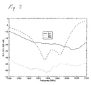
- the diagram shown in fig. 3 illustrates the return loss, which is greater than 19 dB for both channels (S11, S22), and an isolation (S21) of about 35 dB in the frequency band 1.85-1.99 GHz (i.e. the PCS band).
- the feed lines do not have to be micro strip lines but may be conventional coaxial cables with a central conductor and an outer shield, the conductor and the shield being soldered into contact with the opposite edges of the associated slot.
- the conductor and the shield being soldered into contact with the opposite edges of the associated slot.
Landscapes
- Physics & Mathematics (AREA)
- Electromagnetism (AREA)
- Waveguide Aerials (AREA)
- Variable-Direction Aerials And Aerial Arrays (AREA)
Claims (8)
- Ein flaches, aperturgekoppeltes Antennenelement der Art mit einer Mehrschichtstruktur mit einem strahlenden Patch (2), das auf einer dielektrischen Schicht (1) angeordnet ist, einer elektrisch leitenden Erdungsebeneschicht (3) mit einer kreuzförmigen Apertur (4) mit zwei sich kreuzenden Schlitzen (4a, 4b), die in Bezug auf das Patch im wesentlichen zentriert sind, und einer einzigen dielektrischen Platte (5), die mit einem Speisenetz (6) zum Einspeisen von Mikrowellenenergie über Speiseelemente (7, 8) und die kreuzförmige Apertur (4) zum Patch (2) versehen ist, so daß letzteres einen vom Antennenelement ausgehenden dual polarisierten Mikrowellenstrahl erzeugt, dadurch gekennzeichnet, daß die Mehrschichtstruktur die genannte einzige dielektrische Platte (5) aufweist, die mit einem planaren Speisenetzwerk (6) versehen ist, das ein erstes Speiseelement (7) mit einem Paar von symmetrisch auf jeder Seite des Aperturzentrums (4c) verlaufenden Speiseleitungen und ein zweites Speiselement (8) mit einer einzigen unsymmetrisch an einer Seite des Aperturzentrums angeordneten Speiseleitung, die das erste Speiseelement nicht kreuzt, aufweist, wobei die zwei Speiseelemente (8, 7) so orientiert und bemessen sind, daß jedes einen der Schlitze (4a, 4b) getrennt von einem jeweiligen Mikrowellenkanal erregt.
- Antennenelement nach Anspruch 1, dadurch gekennzeichnet, daß das zweite Speiseelement (8) näher am Aperturzentrum angeordnet ist als das erste Speiseelement (7).
- Antennenelement nach Anspruch 1, dadurch gekennzeichnet, daß die zwei Speiseleitungen (7a, 7b) des ersten Speiseelements sich im wesentlichen parallel zueinander und senkrecht bezüglich des zugehörigen Schlitzes (4b) erstrecken.
- Antennenelement nach Anspruch 3, dadurch gekennzeichnet, daß die zwei Speiseleitungen (7a, 7b) im wesentlichen gerade sind und von einer im Netzwerk (6) eingeschlossenen zugehörigen Kanalleitung (7c) abzweigen.
- Antennenelement nach Anspruch 2 und 3, dadurch gekennzeichnet, daß die einzelne Speiseleitung (8) des zweiten Speiseelements zwischen jedoch in einem Abstand von den Endabschnitten (7aa, 7bb) der Speiseleitung des ersten Speiseelements angeordnet ist.
- Antennenelement nach Anspruch 1, dadurch gekennzeichnet, daß das planare Speisenetzwerk (6) aus Mikrostreifenleitungen besteht, die auf der von der Erdungsebene-Schicht (3) abgewandten Seite der dielektrischen Platte (5) angeordnet sind.
- Antennenelement nach Anspruch 6, dadurch gekennzeichnet, daß die Speiseleitungen des ersten und zweiten Speiseelements Stichleitungsabschnitte (7aa, 7bb, 8a) haben, die sich jenseits des Punktes und in einem Abstand davon erstrecken, wo die jeweiligen Speiseelemente den zugehörigen Schlitz kreuzen.
- Antennenelement nach Anspruch 7, dadurch gekennzeichnet, daß die Stichleitungsabschnitte (7aa, 7bb, 8a) innerhalb der vom Speisenetzwerk (6) definierten Ebene in einem Winkel gebogen sind.
Applications Claiming Priority (3)
| Application Number | Priority Date | Filing Date | Title |
|---|---|---|---|
| SE9700208 | 1997-01-24 | ||
| SE9700208A SE9700208L (sv) | 1997-01-24 | 1997-01-24 | Antennelement |
| PCT/SE1998/000071 WO1998033234A1 (en) | 1997-01-24 | 1998-01-16 | A substantially flat, aperture-coupled antenna element |
Publications (2)
| Publication Number | Publication Date |
|---|---|
| EP0954886A1 EP0954886A1 (de) | 1999-11-10 |
| EP0954886B1 true EP0954886B1 (de) | 2004-11-10 |
Family
ID=20405515
Family Applications (1)
| Application Number | Title | Priority Date | Filing Date |
|---|---|---|---|
| EP98901630A Expired - Lifetime EP0954886B1 (de) | 1997-01-24 | 1998-01-16 | Annähernd flaches, aperturgekoppeltes antennenelement |
Country Status (10)
| Country | Link |
|---|---|
| US (1) | US6018319A (de) |
| EP (1) | EP0954886B1 (de) |
| JP (1) | JP3990735B2 (de) |
| CN (1) | CN1126192C (de) |
| AU (1) | AU5786698A (de) |
| BR (1) | BR9806975B1 (de) |
| DE (1) | DE69827471T2 (de) |
| ID (1) | ID19743A (de) |
| SE (1) | SE9700208L (de) |
| WO (1) | WO1998033234A1 (de) |
Families Citing this family (45)
| Publication number | Priority date | Publication date | Assignee | Title |
|---|---|---|---|---|
| SE513586C2 (sv) * | 1998-05-12 | 2000-10-02 | Ericsson Telefon Ab L M | Metod för framställning av en antennstruktur och antennstruktur framställd medelst nämnda metod |
| DE29925006U1 (de) | 1999-09-20 | 2008-04-03 | Fractus, S.A. | Mehrebenenantenne |
| US6239762B1 (en) * | 2000-02-02 | 2001-05-29 | Lockheed Martin Corporation | Interleaved crossed-slot and patch array antenna for dual-frequency and dual polarization, with multilayer transmission-line feed network |
| US6288679B1 (en) * | 2000-05-31 | 2001-09-11 | Lucent Technologies Inc. | Single element antenna structure with high isolation |
| EP1360741A1 (de) * | 2001-02-14 | 2003-11-12 | Telefonaktiebolaget Lm Ericsson | Mehrschichtige streifenleiterantenne |
| EP1239542B1 (de) * | 2001-03-05 | 2006-06-07 | Marconi Communications GmbH | Schlitz-gekoppelte Antennenanordnung auf einem Mehrschicht-Substrat |
| FR2826209A1 (fr) * | 2001-06-15 | 2002-12-20 | Thomson Licensing Sa | Dispositif pour la reception et/ou l'emission de signaux electromagnetiques a diversite de rayonnement |
| US6424299B1 (en) | 2001-08-09 | 2002-07-23 | The Boeing Company | Dual hybrid-fed patch element for dual band circular polarization radiation |
| NL1019022C2 (nl) * | 2001-09-24 | 2003-03-25 | Thales Nederland Bv | Door een patch gevoede gedrukte antenne. |
| BG64431B1 (bg) * | 2001-12-19 | 2005-01-31 | Skygate International Technology N.V. | Антенен елемент |
| JP3928426B2 (ja) * | 2001-12-28 | 2007-06-13 | 松下電器産業株式会社 | アンテナ装置 |
| US20030214438A1 (en) * | 2002-05-20 | 2003-11-20 | Hatch Robert Jason | Broadband I-slot microstrip patch antenna |
| DE10247522A1 (de) * | 2002-10-11 | 2004-04-22 | Infineon Technologies Ag | Dielektrische Patch-Antenne |
| US6885344B2 (en) * | 2002-11-19 | 2005-04-26 | Farrokh Mohamadi | High-frequency antenna array |
| JP4032009B2 (ja) * | 2003-05-21 | 2008-01-16 | 電気興業株式会社 | 偏波アンテナ装置 |
| US7126549B2 (en) * | 2004-12-29 | 2006-10-24 | Agc Automotive Americas R&D, Inc. | Slot coupling patch antenna |
| WO2006091131A1 (en) * | 2005-02-25 | 2006-08-31 | Telefonaktiebolaget Lm Ericsson (Publ) | Uniform communication unit |
| DE102005010895B4 (de) * | 2005-03-09 | 2007-02-08 | Fraunhofer-Gesellschaft zur Förderung der angewandten Forschung e.V. | Aperturgekoppelte Antenne |
| DE102005010894B4 (de) * | 2005-03-09 | 2008-06-12 | Fraunhofer-Gesellschaft zur Förderung der angewandten Forschung e.V. | Planare Mehrbandantenne |
| CN100470928C (zh) * | 2005-05-19 | 2009-03-18 | 上海联能科技有限公司 | 一种无线城域网用基站扇区天线 |
| WO2008148569A2 (en) * | 2007-06-06 | 2008-12-11 | Fractus, S.A. | Dual-polarized radiating element, dual-band dual-polarized antenna assembly and dual-polarized antenna array |
| CN101102012B (zh) * | 2007-07-12 | 2011-04-13 | 上海交通大学 | 多层三维悬空结构的单向宽带圆极化毫米波平面缝隙天线 |
| US7999745B2 (en) * | 2007-08-15 | 2011-08-16 | Powerwave Technologies, Inc. | Dual polarization antenna element with dielectric bandwidth compensation and improved cross-coupling |
| USD634738S1 (en) | 2008-01-30 | 2011-03-22 | Yfy Rfid Technologies Company Limited | RFID antenna |
| TWI355111B (en) * | 2008-01-31 | 2011-12-21 | Yfy Rfid Technologies Company Ltd | Antenna system and antenna thereof |
| US20090231186A1 (en) * | 2008-02-06 | 2009-09-17 | Raysat Broadcasting Corp. | Compact electronically-steerable mobile satellite antenna system |
| SE532035C2 (sv) | 2008-02-25 | 2009-10-06 | Powerwave Technologies Sweden | Antennmatningsarrangemang |
| US8120536B2 (en) | 2008-04-11 | 2012-02-21 | Powerwave Technologies Sweden Ab | Antenna isolation |
| SE532279C2 (sv) | 2008-04-11 | 2009-12-01 | Powerwave Technologies Sweden | Förbättrad antennisolation |
| CN101299486A (zh) * | 2008-06-18 | 2008-11-05 | 北京邮电大学 | 一种覆盖高频和超高频及微波频段的rfid读写器天线 |
| RU2386199C1 (ru) * | 2009-01-11 | 2010-04-10 | Открытое Акционерное Общество "Радиотехнический Институт Имени Академика А.Л. Минца" | Широкополосное волноводное щелевое двухканальное излучающее устройство круговой поляризации |
| US9755306B1 (en) | 2013-01-07 | 2017-09-05 | Lockheed Martin Corporation | Wideband antenna design for wide-scan low-profile phased arrays |
| US10326205B2 (en) * | 2016-09-01 | 2019-06-18 | Wafer Llc | Multi-layered software defined antenna and method of manufacture |
| GB201615108D0 (en) * | 2016-09-06 | 2016-10-19 | Antenova Ltd | De-tuning resistant antenna device |
| US10720695B2 (en) * | 2017-05-15 | 2020-07-21 | Speedlink Technology Inc. | Near field communication antenna modules for devices with metal frame |
| CN109088161B (zh) * | 2018-08-13 | 2021-05-04 | 苏州速感智能科技有限公司 | 工作在毫米波段的微带贴片天线、阵列及阵列设计方法 |
| RU188495U1 (ru) * | 2018-12-11 | 2019-04-16 | Федеральное государственное автономное образовательное учреждение высшего образования "Уральский федеральный университет имени первого Президента России Б.Н. Ельцина" | Миниатюрная микрополосковая антенна |
| CN113519090B (zh) * | 2019-03-14 | 2022-12-27 | 华为技术有限公司 | 用于天线元件的馈电方法和馈电结构 |
| WO2021000073A1 (zh) * | 2019-06-29 | 2021-01-07 | 瑞声声学科技(深圳)有限公司 | 天线振子、天线阵列和基站 |
| US10804609B1 (en) * | 2019-07-24 | 2020-10-13 | Facebook, Inc. | Circular polarization antenna array |
| EP4429020A1 (de) * | 2023-03-09 | 2024-09-11 | Nokia Technologies Oy | Antennenortung in einer vorrichtung |
| CN118645791A (zh) * | 2023-03-13 | 2024-09-13 | 英业达科技有限公司 | 天线装置 |
| CN118676609A (zh) * | 2023-03-14 | 2024-09-20 | 英业达科技有限公司 | 天线装置 |
| CN116191031A (zh) * | 2023-03-31 | 2023-05-30 | 深圳市信维通信股份有限公司 | 一种天线、天线阵列以及通信设备 |
| CN120581861A (zh) * | 2024-03-01 | 2025-09-02 | 英业达科技有限公司 | 天线装置 |
Family Cites Families (5)
| Publication number | Priority date | Publication date | Assignee | Title |
|---|---|---|---|---|
| US4903033A (en) * | 1988-04-01 | 1990-02-20 | Ford Aerospace Corporation | Planar dual polarization antenna |
| US4916457A (en) * | 1988-06-13 | 1990-04-10 | Teledyne Industries, Inc. | Printed-circuit crossed-slot antenna |
| US5241321A (en) * | 1992-05-15 | 1993-08-31 | Space Systems/Loral, Inc. | Dual frequency circularly polarized microwave antenna |
| KR0140601B1 (ko) * | 1995-03-31 | 1998-07-01 | 배순훈 | 이중 원편파 수신장치 |
| US5896107A (en) * | 1997-05-27 | 1999-04-20 | Allen Telecom Inc. | Dual polarized aperture coupled microstrip patch antenna system |
-
1997
- 1997-01-24 SE SE9700208A patent/SE9700208L/ not_active IP Right Cessation
-
1998
- 1998-01-16 BR BRPI9806975-6A patent/BR9806975B1/pt not_active IP Right Cessation
- 1998-01-16 EP EP98901630A patent/EP0954886B1/de not_active Expired - Lifetime
- 1998-01-16 AU AU57866/98A patent/AU5786698A/en not_active Abandoned
- 1998-01-16 WO PCT/SE1998/000071 patent/WO1998033234A1/en not_active Ceased
- 1998-01-16 CN CN98802015A patent/CN1126192C/zh not_active Expired - Lifetime
- 1998-01-16 JP JP53189898A patent/JP3990735B2/ja not_active Expired - Fee Related
- 1998-01-16 DE DE69827471T patent/DE69827471T2/de not_active Expired - Lifetime
- 1998-01-20 ID IDP980066A patent/ID19743A/id unknown
- 1998-01-23 US US09/027,933 patent/US6018319A/en not_active Expired - Lifetime
Also Published As
| Publication number | Publication date |
|---|---|
| SE507076C2 (sv) | 1998-03-23 |
| AU5786698A (en) | 1998-08-18 |
| ID19743A (id) | 1998-07-30 |
| EP0954886A1 (de) | 1999-11-10 |
| BR9806975A (pt) | 2000-03-14 |
| SE9700208D0 (sv) | 1997-01-24 |
| WO1998033234A1 (en) | 1998-07-30 |
| BR9806975B1 (pt) | 2012-05-29 |
| US6018319A (en) | 2000-01-25 |
| CN1244297A (zh) | 2000-02-09 |
| JP2001509341A (ja) | 2001-07-10 |
| SE9700208L (sv) | 1998-03-23 |
| DE69827471T2 (de) | 2005-10-27 |
| JP3990735B2 (ja) | 2007-10-17 |
| CN1126192C (zh) | 2003-10-29 |
| DE69827471D1 (de) | 2004-12-16 |
Similar Documents
| Publication | Publication Date | Title |
|---|---|---|
| US6018319A (en) | Antenna element | |
| US6054953A (en) | Dual band antenna | |
| US5786793A (en) | Compact antenna for circular polarization | |
| US6496148B2 (en) | Antenna with a conductive layer and a two-band transmitter including the antenna | |
| US3971032A (en) | Dual frequency microstrip antenna structure | |
| KR20000011121A (ko) | 평면 안테나장치 | |
| EP1790033B1 (de) | Reflexionsantenne | |
| US20060232474A1 (en) | Antenna system | |
| EP1038332B1 (de) | Zweibandantenne | |
| GB2323970A (en) | A cavity-backed microstrip dipole antenna array | |
| JPH0223702A (ja) | 広帯域アンテナ | |
| KR20050031625A (ko) | 광대역 슬롯 배열 안테나 | |
| CN115149243B (zh) | 双频双极化叠层贴片天线及无线通信设备 | |
| JP2023505332A (ja) | 高電流保護を備えた無指向性水平偏波アンテナ | |
| EP0823749A1 (de) | Integrierte, schichtartig aufgebaute Streifenleiterantenne | |
| US6765537B1 (en) | Dual uncoupled mode box antenna | |
| JP2002344238A (ja) | 偏波共用平面アンテナ | |
| KR100286005B1 (ko) | 마이크로스트립 다이폴 안테나 어레이 | |
| KR100468201B1 (ko) | 두 개의 스파이럴 라인을 이용한 마이크로스트립 스파이럴안테나 | |
| JP2005286854A (ja) | 偏波切換え機能を有するアンテナ | |
| JP3378513B2 (ja) | 平面型指向性アンテナ | |
| Ding et al. | Novel broadband slot antenna with low cross-polarization | |
| KR20050032806A (ko) | 이중대역 인쇄형 다이폴 안테나 | |
| Suzuki et al. | A broadband microstrip antenna fed by a coplanar waveguide with dogbone slot | |
| JP3880789B2 (ja) | 偏波共用平面アンテナ |
Legal Events
| Date | Code | Title | Description |
|---|---|---|---|
| PUAI | Public reference made under article 153(3) epc to a published international application that has entered the european phase |
Free format text: ORIGINAL CODE: 0009012 |
|
| 17P | Request for examination filed |
Effective date: 19990630 |
|
| AK | Designated contracting states |
Kind code of ref document: A1 Designated state(s): DE FR GB IT SE |
|
| GRAP | Despatch of communication of intention to grant a patent |
Free format text: ORIGINAL CODE: EPIDOSNIGR1 |
|
| RIC1 | Information provided on ipc code assigned before grant |
Ipc: 7H 01Q 9/04 B Ipc: 7H 01Q 1/38 B Ipc: 7H 01Q 13/10 A |
|
| RTI1 | Title (correction) |
Free format text: A SUBSTANTIALLY FLAT, APERTURE-COUPLED ANTENNA ELEMENT |
|
| GRAS | Grant fee paid |
Free format text: ORIGINAL CODE: EPIDOSNIGR3 |
|
| GRAA | (expected) grant |
Free format text: ORIGINAL CODE: 0009210 |
|
| AK | Designated contracting states |
Kind code of ref document: B1 Designated state(s): DE FR GB IT SE |
|
| REG | Reference to a national code |
Ref country code: GB Ref legal event code: FG4D |
|
| REF | Corresponds to: |
Ref document number: 69827471 Country of ref document: DE Date of ref document: 20041216 Kind code of ref document: P |
|
| PG25 | Lapsed in a contracting state [announced via postgrant information from national office to epo] |
Ref country code: SE Free format text: LAPSE BECAUSE OF FAILURE TO SUBMIT A TRANSLATION OF THE DESCRIPTION OR TO PAY THE FEE WITHIN THE PRESCRIBED TIME-LIMIT Effective date: 20050210 |
|
| ET | Fr: translation filed | ||
| PLBE | No opposition filed within time limit |
Free format text: ORIGINAL CODE: 0009261 |
|
| STAA | Information on the status of an ep patent application or granted ep patent |
Free format text: STATUS: NO OPPOSITION FILED WITHIN TIME LIMIT |
|
| 26N | No opposition filed |
Effective date: 20050811 |
|
| REG | Reference to a national code |
Ref country code: FR Ref legal event code: PLFP Year of fee payment: 19 |
|
| REG | Reference to a national code |
Ref country code: GB Ref legal event code: 732E Free format text: REGISTERED BETWEEN 20160421 AND 20160428 |
|
| REG | Reference to a national code |
Ref country code: DE Ref legal event code: R082 Ref document number: 69827471 Country of ref document: DE Representative=s name: BOEHMERT & BOEHMERT ANWALTSPARTNERSCHAFT MBB -, DE Ref country code: DE Ref legal event code: R081 Ref document number: 69827471 Country of ref document: DE Owner name: INTEL CORP., SANTA CLARA, US Free format text: FORMER OWNER: ALLGON AB, AKERSBERGA, SE |
|
| REG | Reference to a national code |
Ref country code: FR Ref legal event code: TP Owner name: INTEL CORPORATION, US Effective date: 20160602 Ref country code: FR Ref legal event code: TP Owner name: INTEL CORPORATION, US Effective date: 20160603 Ref country code: FR Ref legal event code: TP Owner name: INTEL CORPORATION, US Effective date: 20160606 Ref country code: FR Ref legal event code: CD Owner name: INTEL CORPORATION, US Effective date: 20160602 |
|
| REG | Reference to a national code |
Ref country code: GB Ref legal event code: 732E Free format text: REGISTERED BETWEEN 20160811 AND 20160817 |
|
| REG | Reference to a national code |
Ref country code: GB Ref legal event code: 732E Free format text: REGISTERED BETWEEN 20161006 AND 20161012 |
|
| REG | Reference to a national code |
Ref country code: GB Ref legal event code: 732E Free format text: REGISTERED BETWEEN 20161013 AND 20161019 |
|
| REG | Reference to a national code |
Ref country code: FR Ref legal event code: PLFP Year of fee payment: 20 |
|
| PGFP | Annual fee paid to national office [announced via postgrant information from national office to epo] |
Ref country code: FR Payment date: 20161229 Year of fee payment: 20 |
|
| PGFP | Annual fee paid to national office [announced via postgrant information from national office to epo] |
Ref country code: DE Payment date: 20170110 Year of fee payment: 20 |
|
| PGFP | Annual fee paid to national office [announced via postgrant information from national office to epo] |
Ref country code: GB Payment date: 20170111 Year of fee payment: 20 |
|
| PGFP | Annual fee paid to national office [announced via postgrant information from national office to epo] |
Ref country code: IT Payment date: 20170123 Year of fee payment: 20 |
|
| REG | Reference to a national code |
Ref country code: DE Ref legal event code: R071 Ref document number: 69827471 Country of ref document: DE |
|
| REG | Reference to a national code |
Ref country code: GB Ref legal event code: PE20 Expiry date: 20180115 |
|
| PG25 | Lapsed in a contracting state [announced via postgrant information from national office to epo] |
Ref country code: GB Free format text: LAPSE BECAUSE OF EXPIRATION OF PROTECTION Effective date: 20180115 |