EP0954657B1 - Betonstütze - Google Patents
Betonstütze Download PDFInfo
- Publication number
- EP0954657B1 EP0954657B1 EP98905315A EP98905315A EP0954657B1 EP 0954657 B1 EP0954657 B1 EP 0954657B1 EP 98905315 A EP98905315 A EP 98905315A EP 98905315 A EP98905315 A EP 98905315A EP 0954657 B1 EP0954657 B1 EP 0954657B1
- Authority
- EP
- European Patent Office
- Prior art keywords
- pillar
- flat
- concrete
- flat strip
- flat strips
- Prior art date
- Legal status (The legal status is an assumption and is not a legal conclusion. Google has not performed a legal analysis and makes no representation as to the accuracy of the status listed.)
- Expired - Lifetime
Links
- 239000004567 concrete Substances 0.000 title claims abstract description 25
- 239000000853 adhesive Substances 0.000 claims abstract description 12
- 230000001070 adhesive effect Effects 0.000 claims abstract description 12
- 239000011230 binding agent Substances 0.000 claims abstract description 12
- 239000011159 matrix material Substances 0.000 claims abstract description 12
- 230000002787 reinforcement Effects 0.000 claims abstract description 11
- 229910000831 Steel Inorganic materials 0.000 claims abstract description 6
- 239000010959 steel Substances 0.000 claims abstract description 6
- 239000002131 composite material Substances 0.000 claims abstract description 5
- IHQKEDIOMGYHEB-UHFFFAOYSA-M sodium dimethylarsinate Chemical class [Na+].C[As](C)([O-])=O IHQKEDIOMGYHEB-UHFFFAOYSA-M 0.000 claims abstract 2
- XLYOFNOQVPJJNP-UHFFFAOYSA-N water Substances O XLYOFNOQVPJJNP-UHFFFAOYSA-N 0.000 claims description 15
- 238000001704 evaporation Methods 0.000 claims description 6
- 230000008020 evaporation Effects 0.000 claims description 6
- 229920005989 resin Polymers 0.000 claims description 6
- 239000011347 resin Substances 0.000 claims description 6
- 229920000049 Carbon (fiber) Polymers 0.000 claims description 5
- 239000004917 carbon fiber Substances 0.000 claims description 5
- 239000003822 epoxy resin Substances 0.000 claims description 5
- 229920000647 polyepoxide Polymers 0.000 claims description 5
- 235000011837 pasties Nutrition 0.000 claims description 3
- 239000011253 protective coating Substances 0.000 claims description 2
- 238000004804 winding Methods 0.000 claims description 2
- 239000012783 reinforcing fiber Substances 0.000 claims 6
- 238000000926 separation method Methods 0.000 claims 3
- 239000000088 plastic resin Substances 0.000 claims 1
- 230000000153 supplemental effect Effects 0.000 claims 1
- 239000011150 reinforced concrete Substances 0.000 abstract description 4
- OKTJSMMVPCPJKN-UHFFFAOYSA-N Carbon Chemical compound [C] OKTJSMMVPCPJKN-UHFFFAOYSA-N 0.000 abstract 2
- 229910052799 carbon Inorganic materials 0.000 abstract 2
- 239000000835 fiber Substances 0.000 description 9
- 238000005452 bending Methods 0.000 description 3
- 239000004744 fabric Substances 0.000 description 2
- 230000000149 penetrating effect Effects 0.000 description 2
- 239000004925 Acrylic resin Substances 0.000 description 1
- 229920000178 Acrylic resin Polymers 0.000 description 1
- 241000446313 Lamella Species 0.000 description 1
- 239000004743 Polypropylene Substances 0.000 description 1
- 238000009825 accumulation Methods 0.000 description 1
- 239000004760 aramid Substances 0.000 description 1
- 229920003235 aromatic polyamide Polymers 0.000 description 1
- 239000011521 glass Substances 0.000 description 1
- 238000004519 manufacturing process Methods 0.000 description 1
- 239000000203 mixture Substances 0.000 description 1
- 229920001225 polyester resin Polymers 0.000 description 1
- 239000004645 polyester resin Substances 0.000 description 1
- -1 polypropylene Polymers 0.000 description 1
- 229920001155 polypropylene Polymers 0.000 description 1
- 229920005749 polyurethane resin Polymers 0.000 description 1
- 230000003014 reinforcing effect Effects 0.000 description 1
- 229920003002 synthetic resin Polymers 0.000 description 1
- 239000000057 synthetic resin Substances 0.000 description 1
Images

Classifications
-
- E—FIXED CONSTRUCTIONS
- E04—BUILDING
- E04G—SCAFFOLDING; FORMS; SHUTTERING; BUILDING IMPLEMENTS OR AIDS, OR THEIR USE; HANDLING BUILDING MATERIALS ON THE SITE; REPAIRING, BREAKING-UP OR OTHER WORK ON EXISTING BUILDINGS
- E04G23/00—Working measures on existing buildings
- E04G23/02—Repairing, e.g. filling cracks; Restoring; Altering; Enlarging
- E04G23/0218—Increasing or restoring the load-bearing capacity of building construction elements
-
- E—FIXED CONSTRUCTIONS
- E04—BUILDING
- E04C—STRUCTURAL ELEMENTS; BUILDING MATERIALS
- E04C3/00—Structural elongated elements designed for load-supporting
- E04C3/30—Columns; Pillars; Struts
- E04C3/34—Columns; Pillars; Struts of concrete other stone-like material, with or without permanent form elements, with or without internal or external reinforcement, e.g. metal coverings
-
- E—FIXED CONSTRUCTIONS
- E04—BUILDING
- E04G—SCAFFOLDING; FORMS; SHUTTERING; BUILDING IMPLEMENTS OR AIDS, OR THEIR USE; HANDLING BUILDING MATERIALS ON THE SITE; REPAIRING, BREAKING-UP OR OTHER WORK ON EXISTING BUILDINGS
- E04G23/00—Working measures on existing buildings
- E04G23/02—Repairing, e.g. filling cracks; Restoring; Altering; Enlarging
- E04G23/0218—Increasing or restoring the load-bearing capacity of building construction elements
- E04G2023/0251—Increasing or restoring the load-bearing capacity of building construction elements by using fiber reinforced plastic elements
Definitions
- the invention relates to a concrete column with a column foot, a column head and, if necessary, a steel reinforcement embedded in the interior of the column with one in the form of a spiral over the column surface extending ribbon, the ribbon being a composite structure a plurality of carrier fibers aligned essentially parallel to one another has and with its one broadside by means of an adhesive on the Support surface is attached.
- Columns are vertical components, their height or length in relation to their cross-sectional dimensions is large.
- the supports serve others Components such as beams or beams as supports and guide their loads in the foundation. This mainly results in a pressure load in the longitudinal direction of the column. Columns can also be supported by horizontal loads such as Wind loads, impact loads or seismic movements are subjected to bending become. With slender supports there is also the risk of Buckling. Depending on the type of manufacture are independent of the load and the risk of buckling stipulates minimum thicknesses for supports. For the reinforcement of columns are subject to the guidelines laid down in DIN 1045. If there is a risk of high impact loads and seismic movements are sufficient however, these guidelines for a kink-proof design of reinforced concrete columns often not out.
- a concrete column of the type mentioned (US 5,043,033) is yours Reinforcement wrapped with a flat ribbon made of supporting fibers.
- the flat ribbon extends in the form of a helix over the support surface so that it is covered by a continuous layer.
- the support of the flat belt is reinforced. Penetrating under the ribbon
- water can hardly escape again, so that the support be damaged by the accumulation of water under the flat belt can.
- Another known concrete support points to its reinforcement layers of fabric impregnated with resin, which make the support tire-like include.
- the surface of this well-known concrete column is also seamless covered by the fabric layers, so that between the support and the Layers of tissue penetrated water poorly back to the environment is delivered. This in turn results in increased vulnerability against damage from between the support and the tissue layers accumulated water.
- the object of the invention is a concrete prop to develop with high buckling protection, which also high horizontal forces and can withstand seismic movements, and more consistently against water.
- the flat band is between the column foot and the column head extends that the supporting fibers are resistant to shear through a binder matrix are interconnected, and that the pitch of the helix is greater than the bandwidth of the flat belt is, with gaps between the windings of the flat belt spiral remaining for the evaporation of accumulated water.
- the pitch is such that there is no closed space between the flat strip and the column surface can form, from which possibly penetrating water could escape more.
- the pitch of the helix corresponds accordingly about 1.1 to 5 times, preferably 1.5 to 2.5 times the flat band width.
- the ribbon is appropriate the support surface by means of at least one fastening element secured so that it cannot come off from the ends.
- the flat strips are fixed at a distance from one another by means of an adhesive on the support surface and the distance between the flat strips 0.1 to 4 times the flat strip width, leaving gaps between the flat strips for the evaporation of accumulated water.
- the flat belts are overlapping ends on the support attached.
- the distance between the flat tapes is such that that there is no closed between the flat strips and the surface of the column Can form a space from which any water can not penetrate could escape more.
- the distance between the flat strips corresponds accordingly 0.1 to 4 times, preferably 0.5 to 1.5 times the flat band width.
- Concrete stumps expediently have the flat strips in their over the Intermediate areas of the column edges are embossed Bend on. This bend can be created in that the flat strips in the areas concerned from their binder matrix freed with exposure of the supporting fibers and with a pasty, curable that replaces the binder matrix Resin can be applied.
- a further increase in the kink protection can be according to one preferred embodiment of the invention can be achieved that additional, the helical or annular arranged Flat ribbons crossing at a distance from each other, by means of an adhesive on the support surface and / or on attached flat tapes provided the existing flat tapes are.
- the supporting fibers of the ribbon are advantageously made Made of carbon fibers, which are characterized by a high modulus of elasticity distinguished.
- flat belts can also be used with aramid, glass or polypropylene fibers or with one Mixture of the fibers mentioned can be used.
- a reaction resin such as epoxy resin
- Polyurethane resin, acrylic resin or polyester resin used as the binder.
- acrylic resin used as the binder.
- polyester resin used for a stable connection of the flat strip to the column surface to ensure there is also the adhesive expediently from a reaction resin of the type mentioned.
- the reinforced concrete column wrapped with the flat tape can also plastered or provided with a protective coating be so that the reinforcement measure from the outside no longer is visible.
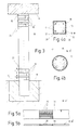
- the concrete supports 10 shown in FIGS. 1, 3 and 5 have a column foot 12 and embedded in a foundation 11 a support head designed as a support for a component 14 16 on.
- the concrete column 10 can be an internal steel reinforcement 17 included (Fig. 4a and b). For further reinforcement to prevent bending or buckling a flat belt 18 (FIG. 1) or with flat belts 18 ', 18' ' wrapped.
- the ribbon 18 extends from Column foot 12 up to the column head 16 helically over the Support surface and is on this with an epoxy resin adhesive 19 attached flat.
- the free ends of the band are through tab-shaped fasteners 20 set on the support.
- the pitch h of the ribbon coil is larger than the bandwidth b. It corresponds to the embodiment shown about 1.5 times the flat band width b.
- the gaps 22 between the flat ribbon turns ensure that between the ribbon and the column surface do not form a continuous closed cavity where water could accumulate.
- Fig. 3 are one Plurality of the support encircling the support by means of a Adhesive flat tapes attached to the column surface 18 'provided, which are arranged at a distance a from each other are that in the embodiment shown corresponds to 0.5 times the flat band width b.
- the ring-shaped flat bands embrace the support with overlapping ends 24 (Fig. 3).
- the flat ribbons consist of a composite structure of one Plurality of parallel aligned, preferably carbon fibers 26 and one which Carrier fibers shear-resistant binding matrix 28 preferably made of epoxy resin.
- the supports 10 can either be a rectangular or have a round cross-section.
- the flat strips expedient in their area overlapping the edges 30 provided with an embossed bend 32 which thereby creates can be that the ribbon 18 'in the relevant Area of its binder matrix 28 exposing the limp support fibers 26 is freed and that after Wrap the area in question with the support Pasty, hardenable synthetic resin replacing binder matrix is applied (Fig. 5a and b).
- the invention refers to a concrete column, especially a round column made of reinforced concrete with a column base 12, a column head 16 and optionally one arranged in the interior of the support Steel reinforcement.
- kink resistance is between the column foot 12 and Column head 16 in the form of a helix over the column surface extending flat band 18 is provided, which is a composite structure from a variety of substantially parallel to each other aligned carbon fibers and one the carbon fibers shear-resistant binding matrix having.
- the flat band 18 is at one Broadside using an adhesive on the column surface attached.
- the pitch h of the ribbon coil is larger chosen as the bandwidth b of the flat band 18.
Landscapes
- Engineering & Computer Science (AREA)
- Architecture (AREA)
- Civil Engineering (AREA)
- Structural Engineering (AREA)
- Chemical & Material Sciences (AREA)
- Chemical Kinetics & Catalysis (AREA)
- Electrochemistry (AREA)
- Mechanical Engineering (AREA)
- Rod-Shaped Construction Members (AREA)
- Working Measures On Existing Buildindgs (AREA)
- Reinforcement Elements For Buildings (AREA)
- Road Signs Or Road Markings (AREA)
Description
- Fig. 1
- eine als Bauwerkstütze ausgebildete Rundstütze mit wendelförmiger Flachbandumwicklung;
- Fig. 2a und b
- einen Flachbandabschnitt in Draufsicht und in Seitenansicht;
- Fig. 3
- eine Bauwerkstütze mit reifenartiger Flachbandumwicklung;
- Fig. 4a und b
- einen Schnitt durch die als Vierkantstütze und als Rundstütze ausgebildete Bauwerkstütze nach Fig. 3;
- Fig. 5a und b
- eine Draufsicht und eine Seitenansicht einer Verstärkungslamelle mit bindemittelfreiem, biegsamem Zwischenbereich;
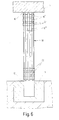
- Fig. 6
- eine Betonstütze mit kreuz- und querverlaufender Flachbandumwicklung.
Claims (13)
- Betonstütze mit einem Stützenfuß (12), einem Stützenkopf (16) sowie gegebenenfalls einer im Stützeninneren angeordneten Stahlbewehrung (17) mit einem sich in Form einer Wendel über die Stützenoberfläche erstreckenden Flachband (18), wobei das Flachband eine Verbundstruktur aus einer Vielzahl von im wesentlichen parallel zueinander ausgerichteten Tragfasern aufweist und mit seiner einen Breitseite mittels eines Klebers an der Stützenoberfläche befestigt ist, dadurch gekennzeichnet, daß das Flachband (18) sich zwischen dem Stützenfuß (12) und dem Stützenkopf (16) erstreckt, daß die Tragfasern durch eine Bindemittelmatrix schubfest miteinander verbunden sind, und daß die Ganghöhe (h) der Wendel größer als die Bandbreite (b) des Flachbandes (18) ist, wobei zwischen den Windungen der Flachband-Wendel Lücken (22) für das Abdampfen von angesammeltem Wasser frei bleiben.
- Betonstütze nach Anspruch 1, dadurch gekennzeichnet, daß das Flachband (18) an seinen freien Enden an der Stützenoberfläche mittels je eines Befestigungselements (20) festgelegt ist.
- Betonstütze nach Anspruch 1 oder 2, dadurch gekennzeichnet, daß die Ganghöhe (h) der Wendel dem 1,1- bis 5-fachen, vorzugsweise dem 1,5- bis 2,5-fachen der Flachbandbreite (b) entspricht.
- Betonstütze mit einem Stützenfuß (12), einem Stützenkopf (16) sowie gegebenenfalls einer im Stützeninneren angeordneten Stahlbewehrung (17), wobei zwischen dem Stützenfuß (12) und dem Stützenkopf (16) mehrere die Stütze reifenartig umfassende Flachbänder (18') an der Stützenoberfläche befestigt sind, wobei die Flachbänder (18') eine Vielzahl von im wesentlichen parallel zueinander ausgerichteten Tragfasern (26) und eine die Tragfasern (26) schubfest miteinander verbindende Bindemittelmatrix (28) aufweisen, dadurch gekennzeichnet, daß die Flachbänder im Abstand voneinander mittels eines Klebers (19) an der Stützenoberfläche befestigt sind und der Abstand (a) zwischen den Flachbändern (18') dem 0,1- bis 4-fachen der Flachbandbreite (b) entspricht, wobei zwischen den Flachbändern Lücken (22) für das Abdampfen von angesammeltem Wasser frei bleiben.
- Betonstütze nach Anspruch 4, dadurch gekennzeichnet, daß die Flachbänder (18') mit einander überlappenden Enden (24) an der Stütze (10) befestigt sind.
- Betonstütze nach Anspruch 4 oder 5, dadurch gekennzeichnet, daß der Abstand (a) zwischen den Flachbändern (18') dem 0,5- bis 1,5-fachen der Flachbandbreite (b) entspricht.
- Betonstütze nach einem der Ansprüche 1 bis 6, dadurch gekennzeichnet, daß zusätzliche, die wendelförmig oder ringförmig angeordneten Flachbänder (18, 18') im Abstand voneinander überkreuzende, mittels eines Klebers (19) an der Stützenoberfläche und/oder an den vorhandenen Flachbändern (18, 18') befestigte Flachbänder (18") vorgesehen sind, wobei zwischen den überkreuzenden Flachbändern (18") Lücken (22) für das Abdampfen von angesammeltem Wasser frei bleiben.
- Betonstütze nach einem der Ansprüche 1 bis 7, dadurch gekennzeichnet, daß die Flachbänder (18, 18', 18") in ihren über Stützenkanten (30) geführten Zwischenbereichen eine aufgeprägte Biegung (32) aufweisen.
- Betonstütze nach Anspruch 8, dadurch gekennzeichnet, daß die Flachbänder (18') im Bereich der aufgeprägten Biegung (32) von ihrer Bindemittelmatrix (28) unter Freilegung der Tragfasern (26) befreit und mit einem die Bindemittelmatrix ersetzenden pastösen, aushärtbaren Kunstharz beaufschlagbar sind.
- Betonstütze nach einem der Ansprüche 1 bis 9, dadurch gekennzeichnet, daß die Tragfasern als Kohlenstoffasern ausgebildet sind.
- Betonstütze nach einem der Ansprüche 1 bis 10, dadurch gekennzeichnet, daß die Bindemittelmatrix aus einem Reaktionsharz, insbesondere aus Epoxidharz besteht.
- Betonstütze nach einem der Ansprüche 1 bis 11, dadurch gekennzeichnet, daß der Kleber aus einem Reaktionsharz, insbesondere aus Epoxidharz besteht.
- Betonstütze nach einem der Ansprüche 1 bis 12, dadurch gekennzeichnet, daß die mit dem Flachband (18) umwickelte Stützenoberfläche verputzt oder mit einem Schutzanstrich versehen ist.
Applications Claiming Priority (3)
| Application Number | Priority Date | Filing Date | Title |
|---|---|---|---|
| DE19702247A DE19702247A1 (de) | 1997-01-23 | 1997-01-23 | Betonstütze |
| DE19702247 | 1997-01-23 | ||
| PCT/EP1998/000271 WO1998032932A1 (de) | 1997-01-23 | 1998-01-20 | Betonstütze |
Publications (2)
| Publication Number | Publication Date |
|---|---|
| EP0954657A1 EP0954657A1 (de) | 1999-11-10 |
| EP0954657B1 true EP0954657B1 (de) | 2003-04-09 |
Family
ID=7818102
Family Applications (1)
| Application Number | Title | Priority Date | Filing Date |
|---|---|---|---|
| EP98905315A Expired - Lifetime EP0954657B1 (de) | 1997-01-23 | 1998-01-20 | Betonstütze |
Country Status (9)
| Country | Link |
|---|---|
| EP (1) | EP0954657B1 (de) |
| JP (1) | JP2000513060A (de) |
| KR (1) | KR100348767B1 (de) |
| AT (1) | ATE237048T1 (de) |
| AU (1) | AU738483B2 (de) |
| CA (1) | CA2278462A1 (de) |
| DE (2) | DE19702247A1 (de) |
| ES (1) | ES2193516T3 (de) |
| WO (1) | WO1998032932A1 (de) |
Families Citing this family (7)
| Publication number | Priority date | Publication date | Assignee | Title |
|---|---|---|---|---|
| WO1999049155A1 (en) * | 1998-03-24 | 1999-09-30 | University Of Ottawa | Retrofitting existing concrete columns by external prestressing |
| JP3484156B2 (ja) * | 1999-12-27 | 2004-01-06 | 構造品質保証研究所株式会社 | 構築物の補強方法及びその構造 |
| AUPR745001A0 (en) * | 2001-09-04 | 2001-09-27 | John Holland Pty Ltd | A method for reinforcing poles |
| EP1411185B1 (de) * | 2002-10-14 | 2013-04-10 | SAG Energieversorgungslösungen GmbH | Verfahren zur nachträglichen Ertüchtigung von Betonmasten |
| US7562499B2 (en) | 2006-01-13 | 2009-07-21 | HC Bridge Company, LLC | Hybrid composite beam system |
| JP2008063744A (ja) * | 2006-09-05 | 2008-03-21 | Nippon Oil Corp | 炭素繊維による既存構造物の補強方法 |
| JP6058332B2 (ja) * | 2012-09-25 | 2017-01-11 | 東日本旅客鉄道株式会社 | コンクリート柱の耐震補強構造及びコンクリート柱の耐震補強方法 |
Citations (1)
| Publication number | Priority date | Publication date | Assignee | Title |
|---|---|---|---|---|
| JPH04189977A (ja) * | 1990-11-22 | 1992-07-08 | Mitsubishi Kasei Corp | 既存コンクリート躯体の補強構造 |
Family Cites Families (4)
| Publication number | Priority date | Publication date | Assignee | Title |
|---|---|---|---|---|
| US4559974A (en) * | 1982-10-01 | 1985-12-24 | Fawley Norman | Apparatus and method of arresting ductile fracture propagation |
| GB8421820D0 (en) * | 1984-08-29 | 1984-10-03 | Balfour Beatty Ltd | Precast concrete piles |
| US5043033A (en) * | 1991-01-28 | 1991-08-27 | Fyfe Edward R | Process of improving the strength of existing concrete support columns |
| US5218810A (en) * | 1992-02-25 | 1993-06-15 | Hexcel Corporation | Fabric reinforced concrete columns |
-
1997
- 1997-01-23 DE DE19702247A patent/DE19702247A1/de not_active Withdrawn
-
1998
- 1998-01-20 JP JP10531555A patent/JP2000513060A/ja active Pending
- 1998-01-20 KR KR1019997006642A patent/KR100348767B1/ko not_active Expired - Fee Related
- 1998-01-20 EP EP98905315A patent/EP0954657B1/de not_active Expired - Lifetime
- 1998-01-20 DE DE59807863T patent/DE59807863D1/de not_active Expired - Fee Related
- 1998-01-20 ES ES98905315T patent/ES2193516T3/es not_active Expired - Lifetime
- 1998-01-20 AU AU60952/98A patent/AU738483B2/en not_active Ceased
- 1998-01-20 WO PCT/EP1998/000271 patent/WO1998032932A1/de not_active Ceased
- 1998-01-20 CA CA002278462A patent/CA2278462A1/en not_active Abandoned
- 1998-01-20 AT AT98905315T patent/ATE237048T1/de not_active IP Right Cessation
Patent Citations (1)
| Publication number | Priority date | Publication date | Assignee | Title |
|---|---|---|---|---|
| JPH04189977A (ja) * | 1990-11-22 | 1992-07-08 | Mitsubishi Kasei Corp | 既存コンクリート躯体の補強構造 |
Also Published As
| Publication number | Publication date |
|---|---|
| DE19702247A1 (de) | 1998-07-30 |
| CA2278462A1 (en) | 1998-07-30 |
| ATE237048T1 (de) | 2003-04-15 |
| ES2193516T3 (es) | 2003-11-01 |
| DE59807863D1 (de) | 2003-05-15 |
| WO1998032932A1 (de) | 1998-07-30 |
| KR20000070408A (ko) | 2000-11-25 |
| JP2000513060A (ja) | 2000-10-03 |
| AU738483B2 (en) | 2001-09-20 |
| AU6095298A (en) | 1998-08-18 |
| KR100348767B1 (ko) | 2002-08-14 |
| EP0954657A1 (de) | 1999-11-10 |
Similar Documents
| Publication | Publication Date | Title |
|---|---|---|
| DE10010935C1 (de) | Kabelhalter für Fahrzeugstrukturen | |
| EP2082131B2 (de) | Mast für eine windturbine | |
| EP3216944B1 (de) | Anordnung zur verstärkung von tragstrukturen | |
| EP0954660B1 (de) | Flachband-lamelle zur verstärkung von bauteilen sowie verfahren zu deren herstellung | |
| EP2912239A1 (de) | Armierungselement zur herstellung vorgespannter betonbauteile, betonbauteil und herstellverfahren | |
| EP0077872A2 (de) | Abdeckeinrichtung | |
| DE2626650A1 (de) | Verfahren zur herstellung von armierten erdbauwerken | |
| EP0954657A1 (de) | Betonstütze | |
| DE2743639A1 (de) | Mit flexiblem stab armierte betonstuetze und verfahren zur herstellung derselben | |
| CH690920A5 (de) | Bewehrung für auf Stützen aufgelagerte Flachdecken, Schubbewehrungselement sowie ein Verfahren zur Herstellung einer Bewehrung. | |
| DE3121418A1 (de) | "schalung" | |
| DE69123517T2 (de) | Verfahren zur Herstellung einer Stahlblechbetondecke | |
| DE1559568B2 (de) | Spannglied | |
| DE4128810C2 (de) | Armierungseinlage | |
| DE19724535C1 (de) | Verbindungselement für Mehrkant-, insbesondere Dreikant-Fachwerkträger | |
| EP1223259B1 (de) | Bewhrung für auf Stützen aufgelagerte Flachdecken sowie ein Verfahren zur Herstellung einer Bewehrung | |
| DE2742918C2 (de) | Gegen zusammengesetzte Beanspruchungen widerstandsfähiger Schlauch | |
| DE102006034618B4 (de) | Filterrohr | |
| DE3039080C2 (de) | Ausbaubares, mehrteiliges Zugglied für einen Verpreßanker | |
| DE3017904A1 (de) | Fassadenelement | |
| DE1559568C3 (de) | ||
| DE102024001307A1 (de) | Komposter | |
| DE3404837A1 (de) | Vorrichtung zur verwahrung von bewehrungsstaehlen | |
| DE102022109350A1 (de) | Mehrschichtiger Hohlkörper aus Textilverbund | |
| DE1800320C (de) | Lager aus elastisch nachgiebigem Werk stoff |
Legal Events
| Date | Code | Title | Description |
|---|---|---|---|
| PUAI | Public reference made under article 153(3) epc to a published international application that has entered the european phase |
Free format text: ORIGINAL CODE: 0009012 |
|
| 17P | Request for examination filed |
Effective date: 19990618 |
|
| AK | Designated contracting states |
Kind code of ref document: A1 Designated state(s): AT CH DE ES FR GB IT LI |
|
| 17Q | First examination report despatched |
Effective date: 20020314 |
|
| GRAG | Despatch of communication of intention to grant |
Free format text: ORIGINAL CODE: EPIDOS AGRA |
|
| RAP1 | Party data changed (applicant data changed or rights of an application transferred) |
Owner name: SIKA SCHWEIZ AG |
|
| GRAG | Despatch of communication of intention to grant |
Free format text: ORIGINAL CODE: EPIDOS AGRA |
|
| GRAG | Despatch of communication of intention to grant |
Free format text: ORIGINAL CODE: EPIDOS AGRA |
|
| GRAH | Despatch of communication of intention to grant a patent |
Free format text: ORIGINAL CODE: EPIDOS IGRA |
|
| GRAH | Despatch of communication of intention to grant a patent |
Free format text: ORIGINAL CODE: EPIDOS IGRA |
|
| GRAA | (expected) grant |
Free format text: ORIGINAL CODE: 0009210 |
|
| AK | Designated contracting states |
Designated state(s): AT CH DE ES FR GB IT LI |
|
| REG | Reference to a national code |
Ref country code: GB Ref legal event code: FG4D Free format text: NOT ENGLISH |
|
| REG | Reference to a national code |
Ref country code: CH Ref legal event code: EP |
|
| GBT | Gb: translation of ep patent filed (gb section 77(6)(a)/1977) | ||
| REG | Reference to a national code |
Ref country code: ES Ref legal event code: FG2A Ref document number: 2193516 Country of ref document: ES Kind code of ref document: T3 |
|
| ET | Fr: translation filed | ||
| PLBE | No opposition filed within time limit |
Free format text: ORIGINAL CODE: 0009261 |
|
| STAA | Information on the status of an ep patent application or granted ep patent |
Free format text: STATUS: NO OPPOSITION FILED WITHIN TIME LIMIT |
|
| 26N | No opposition filed |
Effective date: 20040112 |
|
| PGFP | Annual fee paid to national office [announced via postgrant information from national office to epo] |
Ref country code: AT Payment date: 20060103 Year of fee payment: 9 |
|
| PGFP | Annual fee paid to national office [announced via postgrant information from national office to epo] |
Ref country code: FR Payment date: 20060117 Year of fee payment: 9 |
|
| PGFP | Annual fee paid to national office [announced via postgrant information from national office to epo] |
Ref country code: ES Payment date: 20060126 Year of fee payment: 9 |
|
| PGFP | Annual fee paid to national office [announced via postgrant information from national office to epo] |
Ref country code: IT Payment date: 20060131 Year of fee payment: 9 |
|
| PGFP | Annual fee paid to national office [announced via postgrant information from national office to epo] |
Ref country code: DE Payment date: 20060228 Year of fee payment: 9 |
|
| PGFP | Annual fee paid to national office [announced via postgrant information from national office to epo] |
Ref country code: CH Payment date: 20060630 Year of fee payment: 9 |
|
| PG25 | Lapsed in a contracting state [announced via postgrant information from national office to epo] |
Ref country code: LI Free format text: LAPSE BECAUSE OF NON-PAYMENT OF DUE FEES Effective date: 20070131 Ref country code: CH Free format text: LAPSE BECAUSE OF NON-PAYMENT OF DUE FEES Effective date: 20070131 |
|
| PG25 | Lapsed in a contracting state [announced via postgrant information from national office to epo] |
Ref country code: DE Free format text: LAPSE BECAUSE OF NON-PAYMENT OF DUE FEES Effective date: 20070801 |
|
| REG | Reference to a national code |
Ref country code: CH Ref legal event code: PL |
|
| GBPC | Gb: european patent ceased through non-payment of renewal fee |
Effective date: 20070120 |
|
| REG | Reference to a national code |
Ref country code: FR Ref legal event code: ST Effective date: 20070930 |
|
| PG25 | Lapsed in a contracting state [announced via postgrant information from national office to epo] |
Ref country code: GB Free format text: LAPSE BECAUSE OF NON-PAYMENT OF DUE FEES Effective date: 20070120 Ref country code: AT Free format text: LAPSE BECAUSE OF NON-PAYMENT OF DUE FEES Effective date: 20070120 |
|
| REG | Reference to a national code |
Ref country code: ES Ref legal event code: FD2A Effective date: 20070122 |
|
| PG25 | Lapsed in a contracting state [announced via postgrant information from national office to epo] |
Ref country code: FR Free format text: LAPSE BECAUSE OF NON-PAYMENT OF DUE FEES Effective date: 20070131 |
|
| PG25 | Lapsed in a contracting state [announced via postgrant information from national office to epo] |
Ref country code: ES Free format text: LAPSE BECAUSE OF NON-PAYMENT OF DUE FEES Effective date: 20070122 |
|
| PGFP | Annual fee paid to national office [announced via postgrant information from national office to epo] |
Ref country code: GB Payment date: 20060113 Year of fee payment: 9 |
|
| PG25 | Lapsed in a contracting state [announced via postgrant information from national office to epo] |
Ref country code: IT Free format text: LAPSE BECAUSE OF NON-PAYMENT OF DUE FEES Effective date: 20070120 |