EP0954053A2 - Funkkommunikationsgerät mit Gruppenantenne - Google Patents
Funkkommunikationsgerät mit Gruppenantenne Download PDFInfo
- Publication number
- EP0954053A2 EP0954053A2 EP99108006A EP99108006A EP0954053A2 EP 0954053 A2 EP0954053 A2 EP 0954053A2 EP 99108006 A EP99108006 A EP 99108006A EP 99108006 A EP99108006 A EP 99108006A EP 0954053 A2 EP0954053 A2 EP 0954053A2
- Authority
- EP
- European Patent Office
- Prior art keywords
- calibration
- signal
- power
- reception
- interference
- Prior art date
- Legal status (The legal status is an assumption and is not a legal conclusion. Google has not performed a legal analysis and makes no representation as to the accuracy of the status listed.)
- Withdrawn
Links
Images


Classifications
-
- H—ELECTRICITY
- H01—ELECTRIC ELEMENTS
- H01Q—ANTENNAS, i.e. RADIO AERIALS
- H01Q21/00—Antenna arrays or systems
- H01Q21/28—Combinations of substantially independent non-interacting antenna units or systems
-
- H—ELECTRICITY
- H01—ELECTRIC ELEMENTS
- H01Q—ANTENNAS, i.e. RADIO AERIALS
- H01Q3/00—Arrangements for changing or varying the orientation or the shape of the directional pattern of the waves radiated from an antenna or antenna system
- H01Q3/26—Arrangements for changing or varying the orientation or the shape of the directional pattern of the waves radiated from an antenna or antenna system varying the relative phase or relative amplitude of energisation between two or more active radiating elements; varying the distribution of energy across a radiating aperture
- H01Q3/267—Phased-array testing or checking devices
-
- H—ELECTRICITY
- H01—ELECTRIC ELEMENTS
- H01Q—ANTENNAS, i.e. RADIO AERIALS
- H01Q3/00—Arrangements for changing or varying the orientation or the shape of the directional pattern of the waves radiated from an antenna or antenna system
- H01Q3/26—Arrangements for changing or varying the orientation or the shape of the directional pattern of the waves radiated from an antenna or antenna system varying the relative phase or relative amplitude of energisation between two or more active radiating elements; varying the distribution of energy across a radiating aperture
- H01Q3/30—Arrangements for changing or varying the orientation or the shape of the directional pattern of the waves radiated from an antenna or antenna system varying the relative phase or relative amplitude of energisation between two or more active radiating elements; varying the distribution of energy across a radiating aperture varying the relative phase between the radiating elements of an array
- H01Q3/34—Arrangements for changing or varying the orientation or the shape of the directional pattern of the waves radiated from an antenna or antenna system varying the relative phase or relative amplitude of energisation between two or more active radiating elements; varying the distribution of energy across a radiating aperture varying the relative phase between the radiating elements of an array by electrical means
Definitions
- the present invention relates to array antenna radio communication apparatuses used in radio communication systems.
- An array antenna includes a plurality of antennas and is capable of freely setting reception directivity by adjusting the amplitude and phase of signals received from respective antennas. Adjustments to the amplitude and phase of a received signal can be carried out by multiplying the received signal by a complex coefficient in a received signal processing section.
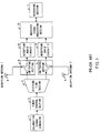
- FIG.1 is a block diagram showing the configuration of a radio communication apparatus equipped with array antennas.
- FIG.1 shows an example of communication apparatus with two antenna devices.
- this communication apparatus When communicating with another communication apparatus, this communication apparatus operates as follows. Radio signals are received through reception antennas 4 and 5. The received radio signals are supplied to reception radio circuits 8 and 9 via switching sections 6 and 7. As the switching sections here, various means can be used such as cable switching, mechanical switches and electronic switches. The received radio signals are down-converted to base frequency band or intermediate frequency band signals in reception radio circuits 8 and 9 and supplied to received signal processing section 10. Inside received signal processing section 10, demodulation processing is performed. The configuration of received signal processing section 10 is determined accordingly by the communication system used.
- bearing reception directivity By bearing directivity it is possible to keep a reception SIR (Signal to Interference Ratio) high.
- reception radio circuits 8 and 9 vary depending on the circuit because of variations in the characteristics of analog devices such as amplifiers. This adds to the received signal of each antenna unknown different amplitude variations and phase rotations, resulting in the formation of reception directivity different from the expected reception directivity obtained by multiplying a complex coefficient in received signal processing section 10.
- Calibration is carried out before starting communications to measure the characteristics of the reception radio circuits. The following is an explanation of the calibration method.
- a calibration signal is generated using calibration signal generator 1. Then, through power control section 2 such as an attenuator, the power of the calibration signal is controlled. The power-controlled calibration signal above is then distributed by distribution section 3, supplied to reception radio circuits 8 and 9 via switching sections 6 and 7.
- distribution section 3 can be implemented using a distributor capable of supplying two or more signals or switches that supply only one signal or cable switching.
- the received signals of the reception radio circuits are observed by received signal processing section 10 and deviations from the expected amplitude and phase of the output signals of reception radio circuits 8 and 9 are stored in a calibration table as the characteristic differences to be corrected at the time of communications. Since the characteristic differences are measured for each reception radio circuit independently, calibration tables are also created independently by the number of reception radio circuits.
- the calibration tables are incorporated in recording section 11 provided inside or outside received signal processing section 10.
- reception calibrations for all antenna branches are completed. Then, the inputs of the reception radio circuits are switched by the switching sections to the reception antennas and communications are started.
- the received signal processing section carries out processing during communications with reference to the calibration tables so that the recorded characteristic differences of the reception radio circuits may be offset.
- phase characteristics of the reception radio circuits measured here result in a combination of phase rotations produced by the reception radio circuits themselves and those produced by the power control section, causing erroneous characteristics to be stored in the calibration tables. This will cause erroneous corrections to be made to the received signals during a communication, preventing correct formation of reception directivity.
- an array antenna radio communication apparatus comprising two calibration signal generators; a calibration desired signal generator and calibration interference signal generator, which controls only the output of the calibration interference signal generator through a power control section and combines this power-controlled calibration interference signal and the calibration desired signal with fixed power into a combined calibration signal using a combination section.
- the power of the calibration desired signal is fixed by the power control section to avoid phase rotations and only the power of the calibration interference signal is changed by the power control section.
- This combined calibration signal is supplied to a plurality of radio circuits simultaneously or alternately and reception processing is applied only to the calibration desired signal in the received signal processing section and its reception characteristics are measured.
- phase of the measured calibration desired received signal will no longer include phase rotations produced by the power control section. This makes it possible to measure the reception characteristics correctly when the power of the received signal varies, create accurate calibration tables and obtain accurate reception directivity using those calibration tables.
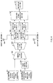
- FIG.2 is a block diagram showing the configuration of an array antenna radio communication apparatus according to Embodiment 1 of the present invention.
- the array antenna radio communication apparatus comprises calibration desired signal generator 101 and calibration interference signal generator 102.
- calibration interference signal generator 102 a section capable of generating random noise and non-modulated sine waves, etc. can be used.
- Power control section 103 adjusts the amplitude of an interference signal from calibration interference signal generator 102.
- an attenuator and variable gain amplifier, etc. may be used as the power control section.
- Combination section 104 combines the calibration desired signal and calibration interference signal and distribution section 105 distributes the combined signal.
- distribution section 105 if it is desired to supply two or more signals simultaneously a distributor may be used, and if it is desired to supply only one signal at a time either a switch or a cable switching section may be used.
- Switching sections 108 and 109 switches between signal input from reception antennas 106 and 107 and calibration signal input. For example, cable switching, mechanical switches or electronic switches, etc. may be used.
- Reception radio circuits 110 and 111 demodulate the signals switched by switch sections 108 and 109.
- Received signal processing section 112 processes the signals using difference values stored in recording section 113.
- an array antenna radio communication apparatus with an array antenna reception function using two antennas, there are two reception antennas, two switching sections and two reception radio circuits.
- switching sections 108 and 109 are set so that the output of distribution section 105 may be supplied to reception radio circuits 110 and 111.
- reception characteristics corresponding to the power of a combined calibration signal at a certain level are measured.
- Calibration desired signal generator 101 generates a calibration desired signal that can be demodulated by received signal processing 112.
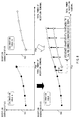
- Power generated Pd is fixed at a certain value.
- the value of Pd is illustrated by white bar graph 201.
- Calibration interference signal generator 102 generates calibration interference signals such as random noise or non-modulated sine waves which can not always be demodulated by received signal processing section 112.
- the power of calibration interference signals is controlled by power control section 103.
- the signal power at the output of power control section 103 is assumed to be Pi.
- the value of Pi is illustrated by shaded bar graph 202.
- a calibration desired signal with signal power Pd and calibration interference signal with signal power Pi are combined by combination section 104 into a combined calibration signal, which in turn is supplied to reception radio circuits 110 and 111 via switching sections 108 and 109.
- the power of the combined calibration signal is Pd + Pi at this time.
- the value Pd + Pi is represented by sum 203 of white bar graph 201 and shaded bar graph 202.
- Received signal processing section 112 obtains a demodulated signal by demodulating the outputs of reception radio circuits 110 and 111. Furthermore, received signal processing section 112 operates so that only the calibration desired signal component may be demodulated. At this time, as stated above, the calibration interference signal is not the one that can not necessarily be demodulated by received signal processing section 112, and thus the calibration interference signal component is superimposed on the demodulated signal as noise.
- received signal processing section 112 observes the demodulated signal obtained in this way and obtains the reception characteristics.
- the reception characteristics include, for example, the phase and amplitude of the demodulated signal.
- Received signal processing section 112 records the deviation from the expected value in the reception characteristics in a calibration table as a characteristic difference to be corrected at the time of communication.
- calibration table 204 In which calibration signal power Pi + Pd is plotted on the horizontal axis and the characteristic difference is plotted on the vertical axis. Since measurements of the characteristic difference are performed independently for each reception radio circuit, calibration tables are also created independently by the number of reception radio circuits. Calibration tables are stored in recording section 113 provided inside or outside the received signal processing section.
- received signal processing section 112 records the deviation from the expected value in the reception characteristics in a calibration table as a characteristic difference to be corrected at the time of communication. When illustrated in a logical image drawing, this would be equivalent to placing plot 209 in calibration table 204.
- calibrations are carried out by keeping the calibration desired signal power constant, while increasing the calibration interference signal power. That is, the power of the calibration interference signal is controlled in order to change the total power when creating a calibration table.
- the difference in the power control section itself is included in (added to) the calibration interference signal.
- the calibration interference signal is simply treated as noise by received signal processing section 112, only the difference of the reception radio circuits can be detected by received signal processing section 112. Therefore, it is possible to create an accurate calibration table that reflects only the difference of the reception radio circuits.
- the reception characteristics are measured for all required power of combined calibration signals and data are recorded in calibration tables. This completes the calibration processing.
- switching sections 108 and 109 are set in such a way that the outputs of reception antennas 106 and 107 are supplied to reception radio circuits 110 and 111.
- Received signal processing section 112 carries out such processing that the measured reception characteristics are offset by referencing the calibration tables created by the calibration processing.
- phase of the measured calibration desired signal does not include phase rotations (differences) generated by the power control section. This makes it possible to carry out accurate measurements of the reception characteristics when the received signal power varies, create accurate calibration tables and obtain accurate reception directivity using those calibration tables.
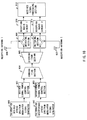
- FIG.4 is a block diagram showing the configuration of an array antenna radio communication apparatus according to Embodiment 2 of the present invention.
- the antenna radio communication apparatus comprises calibration desired digital modulated signal generator 301 and calibration interference digital modulated signal generator 302. Both generators have the same configuration.
- Power control section 303 adjusts the amplitude of a modulated signal from calibration interference digital modulated signal generator 302. Actually, an attenuator and variable gain amplifier, etc. may be used as the power control section.
- Combination section 304 combines the calibration desired digital modulated signal and calibration interference digital modulated signal and distribution section 305 distributes the combined signal.
- distribution section 305 if it is desired to supply two or more signals simultaneously a distributor may be used, and if it is desired to supply only one signal at a time either a switch or a cable switching section may be used.
- Switching sections 308 and 309 receive signals from reception antennas 306 and 307, respectively.
- cable switching sections, mechanical switches and electronic switches, etc. may be used.
- Reception radio circuits 310 and 311 demodulate the signals switched by switch sections 308 and 309.
- Received signal processing section 312 processes the signals using difference values stored in recording section 313.
- an array antenna radio communication apparatus with an array antenna reception function using two antennas, there are two reception antennas, two switching sections and two reception radio circuits.
- switching sections 308 and 309 are set so that the output of distribution section 305 may be supplied to reception radio circuits 310 and 311. First, reception characteristics corresponding to the power of a combined calibration signal at a certain level are measured.
- Calibration desired digital modulated signal generator 301 generates a calibration desired digital modulated signal that can be demodulated by received signal processing 312. The totality or part of the modulation digital information of the calibration desired digital modulated signal must be known to received signal processing section 312. Power generated Pd is fixed at a certain value. In FIG.3, the value of Pd is illustrated by white bar graph 201.
- Calibration interference digital modulated signal generator 302 has the same configuration as that of calibration desired digital modulated signal generator 301 and generates calibration interference digital modulated signals different from calibration desired digital modulated signals.
- the power of calibration interference digital modulated signals is controlled by power control section 303.
- the signal power at the output of power control section 303 is assumed to be Pi.
- the value of Pi is illustrated by shaded bar graph 202.
- a calibration desired digital modulated signal with signal power Pd and calibration interference digital modulated signal with signal power Pi are combined by combination section 304 into a combined calibration digital modulated signal, which in turn is supplied to reception radio circuits 310 and 311 via switching sections 308 and 309.
- the power of the combined calibration signal at this time is Pd + Pi.
- the value Pd + Pi is represented by sum 203 of white bar graph 201 and shaded bar graph 202.
- Received signal processing section 312 obtains a demodulated signal by demodulating the outputs of reception radio circuits 310 and 311.
- the calibration desired digital modulated signal component needs to be demodulated, but it has the calibration interference digital modulated signal component superimposed on it and it is usually impossible to demodulate it. Therefore, the demodulated signal of the combined calibration digital modulated signal is multiplied by a known modulation digital information series of the calibration interference digital modulated signal and the result is integrated. This makes the calibration interference digital modulated signal component averaged and suppressed, making it possible to extract only the calibration desired digital modulated signal component.
- received signal processing section 312 observes the demodulated signal obtained in this way and obtains the reception characteristics.
- the reception characteristics include, for example, the phase and amplitude of the demodulated signal.
- Received signal processing section 312 records the deviation from the expected value in the reception characteristics in a calibration table as a characteristic difference to be corrected at the time of communication.
- the calibration tables are the same as those in Embodiment 1.
- the calibration tables are stored in recording section 313 provided inside or outside the received signal processing section.
- received signal processing section 312 records the deviation from the expected value in the reception characteristics in a calibration table as a characteristic difference to be corrected at the time of communication. When illustrated in a logical image drawing, this would be equivalent to placing plot 209 in calibration table 204.
- calibrations are carried out by keeping the calibration desired digital modulated signal power constant, while increasing the calibration interference digital modulated signal power. That is, the power of the calibration interference digital modulated signal is controlled in order to change the total power when creating a calibration table.
- the difference in the power control section itself is only included in the calibration interference digital modulated signal.
- received signal processing section 312 averages and suppresses the calibration interference digital modulated signal by multiplying the demodulated signal by a modulated digital information series and integrating it. This allows received signal processing section 312 to extract only the calibration desired digital modulated signal component, making it possible to detect the difference only from the reception radio circuits. Therefore, it is possible to create an accurate calibration table that reflects only the difference of the reception radio circuits.
- the reception characteristics are measured for all required power of combined calibration signals and data are recorded in calibration tables. This completes the calibration processing.
- switching sections 308 and 309 are set in such a way that the outputs of reception antennas 306 and 307 are supplied to reception radio circuits 310 and 311.
- Received signal processing section 312 carries out such processing that the measured reception characteristics are offset by referencing the calibration tables created by the calibration processing.
- the phase of the measured calibration desired digital modulated signal does not include phase rotations generated by the power control section. This makes it possible to carry out accurate measurements of the reception characteristics when the received signal power varies, create accurate calibration tables and obtain accurate reception directivity using those calibration tables.
- the calibration interference digital modulated signal generator can have the same configuration as that of the calibration desired digital modulated signal generator, it has an advantage that the transmission section inside the communication apparatus can be diverted as the calibration interference digital modulated signal generator eliminating the necessity of providing a dedicated calibration signal generator which can generate random noise.
- FIG.5 is a block diagram showing the configuration of an array antenna radio communication apparatus according to Embodiment 3 of the present invention.
- the antenna radio communication apparatus comprises calibration desired spread spectrum modulated signal generator 401 and calibration interference spread spectrum modulated signal generator 402. Both generators have the same configuration and carry out spread spectrum modulation using mutually different spreading codes.
- Power control section 403 adjusts the amplitude of a modulated signal from calibration interference spread spectrum modulated signal generator 402. It is possible to use an attenuator and variable gain amplifier as the actual power control section.
- Combination section 404 combines the calibration desired spread spectrum modulated signal and calibration interference spread spectrum modulated signal and distribution section 405 distributes the combined signal.
- distribution section 405 if it is desired to supply two or more signals simultaneously a distributor may be used, and if it is desired to supply only one signal at a time either a switch or a cable switching section may be used.
- Switching sections 408 and 409 receive signals from reception antennas 406 and 407, respectively.
- cable switching sections, mechanical switches and electronic switches, etc. may be used for switching sections 308 and 309.
- Reception radio circuits 410 and 411 demodulate the signals switched by switch sections 408 and 409.
- Received signal processing section 412 processes the signals using difference values stored in recording section 413.
- 410 and 411 are reception radio circuits.
- an array antenna radio communication apparatus with an array antenna reception function using two antennas, there are two reception antennas, two switching sections and two reception radio circuits.
- switching sections 408 and 409 are set so that the output of distribution section 405 may be supplied to reception radio circuits 410 and 411. First, reception characteristics corresponding to the power of a combined calibration spread spectrum modulated signal at a certain level are measured.
- Calibration desired spread spectrum modulated signal generator 401 generates a calibration desired spread spectrum modulated signal that can be demodulated by received signal processing 412.
- the spreading codes of the calibration desired spread spectrum modulated signal must be known to received signal processing 412.
- Power generated Pd is fixed at a certain value. In FIG. 3, the value of Pd is illustrated by white bar graph 401.
- Calibration interference spread spectrum modulated signal generator 402 has the same configuration as that of calibration desired spread spectrum modulated signal generator 401 and generates calibration interference spread spectrum modulated signals whose spreading code is different from that of calibration desired spread spectrum modulated signals.
- the power of calibration interference spread spectrum modulated signals is controlled by power control section 403.
- the signal power at the output of power control section 403 is assumed to be Pi.
- the value of Pi is illustrated by shaded bar graph 202.
- a calibration desired spread spectrum modulated signal with signal power Pd and calibration interference spread spectrum modulated signal with signal power Pi are combined by combination section 404 into a combined calibration spread spectrum modulated signal, which in turn is supplied to reception radio circuits 410 and 411 via switching sections 408 and 409.
- the power of the combined calibration spread spectrum modulated signal at this time is Pd + Pi.
- the value Pd + Pi is represented by sum 203 of white bar graph 201 and shaded bar graph 202.
- Received signal processing section 412 obtains a demodulated signal by demodulating the outputs of reception radio circuits 410 and 411.
- the calibration desired spread spectrum modulated signal component needs to be demodulated, but since the spreading code of the calibration desired spread spectrum modulated is known to received signal processing section 412, it is possible to extract the calibration desired spread spectrum modulated signal component by finding correlation with this spreading code and combined calibration spread spectrum modulated signal.
- received signal processing section 412 observes the demodulated signal obtained in this way and obtains the reception characteristics.
- the reception characteristics include, for example, the phase and amplitude of the demodulated signal.
- Received signal processing section 412 records the deviation from the expected value in the reception characteristics in a calibration table as a characteristic difference to be corrected at the time of communication.
- the calibration tables are the same as those in Embodiment 1.
- the calibration tables are stored in recording section 413 provided inside or outside the received signal processing section.
- received signal processing section 412 records the deviation from the expected value in the reception characteristics in a calibration table as a characteristic difference to be corrected at the time of communication. When illustrated in a logical image drawing, this would be equivalent to placing plot 209 in calibration table 204.
- calibrations are carried out by keeping the power of the calibration desired spread spectrum modulated signal constant, while increasing the calibration interference spread spectrum modulated signal power. That is, the power of the calibration interference spread spectrum modulated signal is controlled in order to change the total power when creating a calibration table.
- the difference in the power control section itself is only included in the calibration interference spread spectrum modulated signal.
- received signal processing section 412 can extract only the calibration desired spread spectrum modulated signal component by finding correlation between the spreading code and the combined calibration spread spectrum modulated signal, making it possible to detect only the difference of the reception radio circuits.
- the reception characteristics are measured for all required power of combined calibration spread spectrum modulated signals and data are recorded in calibration tables. This completes the calibration processing.
- switching sections 408 and 409 are set in such a way that the outputs of reception antennas 406 and 407 are supplied to reception radio circuits 410 and 411.
- Received signal processing section 412 carries out such processing that the measured reception characteristics are offset by referencing the calibration tables created by the calibration processing.
- the phase of the measured calibration desired spread spectrum signal does not include phase rotations generated by the power control section. This makes it possible to carry out accurate measurements of the reception characteristics when the received signal power varies, create accurate calibration tables and obtain accurate reception directivity using those calibration tables.
- the calibration interference spread spectrum modulated signal generator can have the same configuration as that of the calibration desired spread spectrum modulated signal generator, it has an advantage that the transmission section inside the communication apparatus can be diverted as the calibration interference spread spectrum modulated signal generator eliminating the necessity of providing a dedicated calibration signal generator which can generate random noise.
- received signal processing section 412 can suppress noise to a small value by adjusting the type and timing of a spreading code so as to reduce the correlation between the spreading code used by the calibration desired spread spectrum modulated signal generator and the spreading code used by the calibration interference spread spectrum modulated signal generator, it is possible to measure the reception characteristic for the calibration desired spread spectrum modulated signal with high precision.
- calibration desired signal power Pd must be fixed during a calibration.
- the ratio of calibration desired signal power to the calibration interference signal power greatly deteriorates.
- Embodiment 4 is intended to compensate this drawback so that changing calibration desired signal power Pd according to the required combination signal power may not affect characteristic measurements.
- FIG.6 is a block diagram showing the configuration of an array antenna radio communication apparatus according to Embodiment 4 of the present invention.
- the array antenna radio communication apparatus comprises calibration desired signal generator 500 and calibration interference signal generator 502.
- a section that can generate random noise or non-modulated sine waves can be used as calibration interference signal generator 502.
- Desired signal power control section 501 adjusts the amplitude of a calibration desired signal from calibration desired signal generator 500.
- Interference signal power control section 503 adjusts the amplitude of a calibration interference signal from calibration interference signal generator 502. It is possible to use an attenuator and variable gain amplifier as the actual power control section.
- Combination section 504 combines the calibration desired signal and calibration interference signal and distribution section 505 distributes the combined signal.
- distribution section 505 if it is desired to supply two or more signals simultaneously a distributor may be used, and if it is desired to supply only one signal at a time either a switch or a cable switching section may be used.
- Switching sections 508 and 509 receive signals from reception antennas 506 and 507, respectively.
- cable switching sections, mechanical switches and electronic switches, etc. may be used.
- Reception radio circuits 510 and 511 demodulate the signals switched by switch sections 508 and 509.
- Received signal processing section 512 processes the signals using difference values stored in recording section 513.
- an array antenna radio communication apparatus with an array antenna reception function using two antennas, there are two reception antennas, two switching sections and two reception radio circuits.
- switching sections 508 and 509 are set so that the output of distribution section 505 may be supplied to reception radio circuits 510 and 511. First, reception characteristics corresponding to the power of a combined calibration signal at a certain level are measured.
- Calibration desired signal generator 500 generates a calibration desired signal that can be demodulated by received signal processing 512.
- Power generated Pd is fixed at a certain value using power control section 501.
- the value of Pd is illustrated by white bar graph 601.
- Calibration interference signal generator 502 generates calibrations interference signals such as random noise and non-modulated sine waves that can not necessarily be demodulated by received signal processing section 512.
- the power of calibration interference signals is controlled by power control section 503.
- the signal power at the output of power control section 503 is assumed to be Pi.
- the value of Pi is illustrated by shaded bar graph 602.
- a calibration desired signal with signal power Pd and calibration interference signal with signal power Pi are combined by combination section 504 into a combined calibration signal, which in turn is supplied to reception radio circuits 510 and 511 via switching sections 508 and 509.
- the power of the combined calibration signal at this time is Pd + Pi.
- the value Pd + Pi is represented by sum 603 of white bar graph 601 and shaded bar graph 602.
- Received signal processing section 512 obtains a demodulated signal by demodulating the outputs of reception radio circuits 510 and 511. Received signal processing section 512 operates so that only the calibration desired signal component may be demodulated. The calibration interference signal component is superimposed on the demodulated signal as noise.
- received signal processing section 512 observes the demodulated signal and obtains the reception characteristics.
- the reception characteristics include, for example, the phase and amplitude of the demodulated signal.
- Received signal processing section 512 records the deviation from the expected value in the reception characteristics in calibration table A604 as a characteristic difference to be corrected at the time of communication.
- calibration table A604 When illustrated in a logical image drawing, this would be equivalent to placing plot 605 in calibration table A604 in which calibration signal power Pi + Pd is plotted on the horizontal axis and the characteristic difference is plotted on the vertical axis. Since measurements of the characteristic difference are performed independently for each reception radio circuit, calibration table A604 is also created independently by the number of reception radio circuits. Calibration table A604 is stored in recording section 513 provided inside or outside the received signal processing section.
- received signal processing section 512 records the deviation from the expected value in the reception characteristics in calibration table A604 as a characteristic difference to be corrected at the time of communication. When illustrated in a logical image drawing, this would be equivalent to placing plot 609 in calibration table A604.
- calibration table A604 is recorded. This completes calibration table A604.
- calibration table A604 After calibration table A604 is completed, the settings of power control section 501 and 503 are changed.
- combined calibration signal power (Pd+Pi) is set equal to aforementioned switching point power (Psw) 610.
- Psw switching point power
- the calibration desired signal power (Pd) which was small until then is increased and the calibration desired signal power (Pd) which was large until then is decreased.
- only the setting of power control section 503 is changed and by changing only the calibration interference signal power, measurements of the reception characteristics are repeated and calibration table B612 is created in recording section 513.
- calibration table A604 and calibration table B612 are combined into a combined calibration table.
- the combination method is explained using FIG.8 below.
- Combination calibration table 703 is completed by carrying out a parallel translation of all plots of combination calibration table 703 by W.
- the characteristic curve in the corrected combination calibration table becomes a continuous curve without abrupt drops or falls.
- this calibration method carries out calibrations by increasing the calibration interference signal while keeping the calibration desired signal constant (with power switching). That is, the power of the calibration interference signal is controlled to change the total power when creating a calibration table. Therefore, the difference of the power control section itself is included in the calibration interference signal.
- the calibration interference signal is simply handled as noise by received signal processing section 112, received signal processing section 112 can detect only the difference of the reception radio circuits. Therefore, it is possible to create an accurate calibration table which reflects only the difference of the reception radio circuits.
- This embodiment showed an example of creating a calibration table by dividing it into two stages A and B, but it is obvious that it is also possible to create a calibration table by dividing it into three stages.
- switching sections 508 and 509 are set in such a way that the outputs of reception antennas 506 and 507 are supplied to reception radio circuits 510 and 511.
- Received signal processing section 512 carries out such processing that the measured reception characteristics are offset by referencing the calibration tables created by the calibration processing.
- the phase of the measured calibration desired signal does not include phase rotations generated by the power control section even if the calibration desired signal power is changed. Furthermore, when measuring characteristics with large combined calibration signal power, it is possible to prevent the ratio of calibration desired signal power to the calibration interference signal power from drastically deteriorating.
- calibration desired digital modulated signal power Pd must be fixed during a calibration.
- the ratio of calibration desired digital modulated signal power to the calibration interference digital modulated signal power greatly deteriorates.
- Embodiment 5 is intended to compensate this drawback so that changing calibration desired digital modulated signal power Pd according to the required combined calibration digital modulated signal power may not affect characteristic measurements.
- FIG.9 is a block diagram showing the configuration of an array antenna radio communication apparatus according to Embodiment 5 of the present invention.
- the array antenna radio communication apparatus comprises calibration desired digital modulated signal generator 800 and calibration interference digital modulated signal generator 802. Calibration desired digital modulated signal generator 800 and calibration interference digital modulated signal generator 802 have the same configuration.
- Desired signal power control section 801 adjusts the amplitude of a calibration desired digital modulated signal from calibration desired digital modulated signal generator 800.
- Interference digital modulated signal power control section 803 adjusts the amplitude of a calibration interference digital modulated signal from calibration interference digital modulated signal generator 802. It is possible to use an attenuator and variable gain amplifier as the actual power control section.
- Combination section 804 combines the calibration desired digital modulated signal and calibration interference digital modulated signal and distribution section 805 distributes the combined signal.
- distribution section 805 if it is desired to supply two or more signals simultaneously a distributor may be used, and if it is desired to supply only one signal at a time either a switch or a cable switching section may be used.
- Switching sections 808 and 809 receive signals from reception antennas 806 and 807, respectively. For switching sections, cable switching sections, mechanical switches and electronic switches, etc. may be used. Reception radio circuits 810 and 811 demodulate the signals switched by switch sections 808 and 809. Received signal processing section 812 processes the signals using difference values stored in recording section 813.
- an array antenna radio communication apparatus with an array antenna reception function using two antennas, there are two reception antennas, two switching sections and two reception radio circuits.
- switching sections 808 and 809 are set so that the output of distribution section 805 may be supplied to reception radio circuits 810 and 811. First, reception characteristics corresponding to the power of a combined calibration signal at a certain level are measured.
- Calibration desired digital modulated signal generator 800 generates a calibration desired digital modulated signal that can be demodulated by received signal processing 812. The totality or part of the modulation digital information of the calibration desired digital modulated signal needs to be known to received signal processing section 812. Power generated Pd is fixed at a certain value using power control section 801. In FIG.7, the value of Pd is illustrated by white bar graph 601.
- Calibration interference digital modulated signal generator 802 has the same configuration as that of calibration desired digital modulated signal generator 800 and generates calibrations interference digital modulated signals whose modulation digital information is different from that of the calibration desired digital modulated signal.
- the power of calibration interference digital modulated signals is controlled by power control section 803.
- the signal power at the output of power control section 803 is assumed to be Pi.
- the value of Pi is illustrated by shaded bar graph 602.
- a calibration desired digital modulated signal with signal power Pd and calibration interference digital modulated signal with signal power Pi are combined by combination section 804 into a combined calibration signal, which in turn is supplied to reception radio circuits 810 and 811 via switching sections 808 and 809.
- the power of the combined calibration signal at this time is Pd + Pi.
- the value Pd + Pi is represented by sum 603 of white bar graph 601 and shaded bar graph 602.
- Received signal processing section 812 obtains a demodulated signal by demodulating the outputs of reception radio circuits 810 and 811.
- the demodulated signal of the combined calibration digital modulated signal is multiplied by a known modulation digital information series of the calibration interference digital modulated signal and the result is integrated. This makes the calibration interference digital modulated signal component averaged and suppressed, making it possible to extract only the calibration desired digital modulated signal component.
- received signal processing section 812 observes the demodulated signal obtained in this way and obtains the reception characteristics.
- the reception characteristics include, for example, the phase and amplitude of the demodulated signal.
- Received signal processing section 812 records the deviation from the expected value in the reception characteristics in calibration table A604 as a characteristic difference to be corrected at the time of communication.
- calibration table A604 When illustrated in a logical image drawing, this would be equivalent to placing plot 605 in calibration table A604 in which calibration digital modulated signal power Pi + Pd is plotted on the horizontal axis and the characteristic difference is plotted on the vertical axis. Since measurements of the characteristic difference are performed independently for each reception radio circuit, calibration table A604 is also created independently by the number of reception radio circuits. Calibration table A604 is stored in recording section 813 provided inside or outside the received signal processing section.
- calibration interference digital modulated signal power Pi is changed and set to a value expressed by shaded graph 602.
- Pd is expressed by white bar graph 607 as high as white bar graph 601.
- the combined calibration signal power at this time is Pd + Pi.
- value Pd + Pi is illustrated by sum 608 of white bar graph 607 and shaded bar graph 606.
- received signal processing section 812 records the deviation from the expected value in the reception characteristics in calibration table A604 as a characteristic difference to be corrected at the time of communication. When illustrated in a logical image drawing, this would be equivalent to placing plot 609 in calibration table A604.
- calibration table A604 is recorded. This completes calibration table A604.
- calibration digital modulated signal power (Pd+Pi) is set equal to aforementioned switching point power (Psw) 610.
- Psw switching point power
- the calibration desired digital modulated signal power (Pd) which was small until then is increased and the calibration digital modulated desired signal power (Pd) which was large until then is decreased.
- only the setting of power control section 803 is changed and by changing only the calibration interference digital modulated signal power, measurements of the reception characteristics are repeated and calibration table B612 is created in recording section 813.
- calibration table A604 and calibration table B612 are combined into combined calibration table 614.
- the combination method is the same as that in Embodiment 4, and thus its explanation is omitted.
- this calibration method carries out calibrations by increasing the calibration interference digital modulated signal while keeping the calibration desired digital modulated signal constant (with power switching). That is, the power of the calibration interference digital modulated signal is controlled to change the total power when creating a calibration table. Therefore, the difference of the power control section itself is only included in the calibration interference digital modulated signal.
- the calibration interference digital modulated signal is averaged and suppressed by received signal processing section 812 by multiplying the modulated signal by a modulated digital information series and integrating it. This allows received signal processing section 812 to extract only the calibration desired digital modulated signal component and detect only the difference of the reception radio circuits. Therefore, it is possible to create an accurate calibration table which reflects only the difference of the reception radio circuits.
- This embodiment showed an example of creating a calibration table by dividing it into two stages A and B, but it is obvious that it is also possible to create a calibration table by dividing it into three stages.
- switching sections 808 and 809 are set in such a way that the outputs of reception antennas 806 and 807 are supplied to reception radio circuits 810 and 811.
- Received signal processing section 812 carries out such processing that the measured reception characteristics are offset by referencing the calibration tables created by the calibration processing.
- the phase of the measured calibration desired digital modulated signal does not include phase rotations generated by the power control section even if the calibration desired digital modulated signal power is changed. Furthermore, when measuring characteristics with large combined calibration signal power, it is possible to prevent the ratio of calibration desired digital modulated signal power to the calibration interference digital modulated signal power from drastically deteriorating.
- the calibration interference digital modulated signal generator can have the same configuration as that of the calibration desired digital modulated signal generator, it has an advantage that the transmission section inside the communication apparatus can be diverted as the calibration interference digital modulated signal generator, eliminating the necessity of providing a dedicated calibration signal generator which can generate random noise.
- calibration desired spread spectrum modulated signal power Pd must be fixed during a calibration.
- the ratio of calibration desired spread spectrum modulated signal power to the calibration interference spread spectrum modulated signal power greatly deteriorates.
- Embodiment 6 is intended to compensate this drawback so that changing calibration desired spread spectrum modulated signal power Pd according to the required combined spread spectrum modulated signal power may not affect characteristic measurements.
- FIG. 10 is a block diagram showing the configuration of an array antenna radio communication apparatus according to Embodiment 6 of the present invention.
- the array antenna radio communication apparatus comprises calibration desired spread spectrum modulated signal generator 900 and calibration interference spread spectrum modulated signal generator 902.
- Calibration desired spread spectrum modulated signal generator 900 and calibration interference spread spectrum modulated signal generator 902 have virtually the same configuration and have mutually different spreading codes.
- Desired signal power control section 901 adjusts the amplitude of a calibration desired spread spectrum modulated signal from calibration desired spread spectrum modulated signal generator 900.
- Interference spread spectrum modulated signal power control section 903 adjusts the amplitude of a calibration interference spread spectrum modulated signal from calibration interference spread spectrum modulated signal generator 902. It is possible to use an attenuator and variable gain amplifier as the actual power control section.
- Combination section 904 combines the calibration desired spread spectrum modulated signal and calibration interference spread spectrum modulated signal and distribution section 905 distributes the combined signal.
- distribution section 905 if it is desired to supply two or more signals simultaneously a distributor may be used, and if it is desired to supply only one signal at a time either a switch or a cable switching section may be used.
- Switching sections 908 and 909 receive signals from reception antennas 906 and 907, respectively.
- Reception radio circuits 910 and 911 demodulate the signals switched by switch sections 908 and 909.
- Received signal processing section 912 processes the signals using difference values stored in recording section 913.
- an array antenna radio communication apparatus with an array antenna reception function using two antennas, there are two reception antennas, two switching sections and two reception radio circuits.
- switching sections 908 and 909 are set so that the output of distribution section 905 may be supplied to reception radio circuits 910 and 911.
- reception characteristics corresponding to the power of a combined calibration spread spectrum modulated signal at a certain level are measured.
- Calibration desired spread spectrum modulated signal generator 900 generates a calibration desired spread spectrum modulated signal that can be demodulated by received signal processing 912.
- the spreading code of the calibration desired spread spectrum modulated signal needs to be known to received signal processing section 912.
- Power generated Pd is fixed at a certain value using power control section 901. In FIG. 7, the value of Pd is illustrated by white bar graph 601.
- Calibration interference spread spectrum modulated signal generator 902 has the same configuration as that of calibration desired spread spectrum modulated signal generator 900 and generates calibrations interference spread spectrum modulated signals whose spreading code is different from that of the calibrations desired spread spectrum modulated signal.
- the power of calibration interference spread spectrum modulated signals is controlled by power control section 903.
- the signal power at the output of power control section 903 is assumed to be Pi.
- the value of Pi is illustrated by shaded bar graph 602.
- a calibration desired spread spectrum modulated signal with signal power Pd and calibration interference spread spectrum modulated signal with signal power Pi are combined by combination section 904 into a combined calibration spread spectrum modulated signal, which in turn is supplied to reception radio circuits 910 and 911 via switching sections 908 and 909.
- the power of the combined calibration signal at this time is Pd + Pi.
- the value Pd + Pi is represented by sum 603 of white bar graph 601 and shaded bar graph 602.
- Received signal processing section 912 obtains a demodulated signal by demodulating the outputs of reception radio circuits 910 and 911.
- a demodulated signal it is required that only the component of the calibration desired spread spectrum modulated signal be demodulated, but since the spreading code of the calibration desired spread spectrum modulated signal is known to received signal processing section 912, it is possible to extract the calibration desired spread spectrum modulated signal by finding correlation between this spreading code and combined calibration spread spectrum modulated signal.
- received signal processing section 912 observes the demodulated signal and obtains the reception characteristics.
- the reception characteristics include, for example, the phase and amplitude of the demodulated signal.
- Received signal processing section 912 records the deviation from the expected value in the reception characteristics in calibration table A604 as a characteristic difference to be corrected at the time of communication. When illustrated in a logical image drawing, this would be equivalent to placing plot 605 in calibration table A604 in which calibration spread spectrum modulated signal power Pi + Pd is plotted on the horizontal axis and the characteristic difference is plotted on the vertical axis. Since measurements of the characteristic difference are performed independently for each reception radio circuit, calibration table A604 is also created independently by the number of reception radio circuits. Calibration table A604 is stored in recording section 913 provided inside or outside the received signal processing section.
- received signal processing section 912 records the deviation from the expected value in the reception characteristics in calibration table A604 as a characteristic difference to be corrected at the time of communication. When illustrated in a logical image drawing, this would be equivalent to placing plot 609 in calibration table A604.
- calibration table A604 is recorded. This completes calibration table A604.
- calibration table A604 After calibration table A604 is completed, the settings of power control section 901 and 903 are changed.
- combined calibration spread spectrum modulated signal power (Pd+Pi) is set equal to aforementioned switching point power (Psw) 610.
- Psw switching point power
- the calibration desired spread spectrum modulated signal power (Pd) which was small until then is increased and the calibration spread spectrum modulated desired signal power (Pd) which was large until then is decreased.
- only the setting of power control section 903 is changed and by changing only the calibration interference spread spectrum modulated signal power, measurements of the reception characteristics are repeated and calibration table B612 is created in recording section 913.
- calibration table A604 and calibration table B612 are combined into combined calibration table 614.
- the combination method is the same as that in Embodiment 4, and thus its explanation is omitted.
- this calibration method carries out calibrations by increasing the calibration interference spread spectrum modulated signal while keeping the calibration desired spread spectrum modulated signal constant (with power switching). That is, the power of the calibration interference spread spectrum modulated signal is controlled to change the total power when creating a calibration table. Therefore, the difference of the power control section itself is only included in the calibration interference spread spectrum modulated signal.
- received signal processing section 912 can extract only the calibration desired digital modulated signal component by finding correlation between the spreading code and the combined calibration spread spectrum modulated signal, making it possible to detect only the difference of the reception radio circuits. Thus, it is possible to create an accurate calibration table which reflects the difference of only the reception radio circuits.
- This embodiment showed an example of creating a calibration table by dividing it into two stages A and B, but it is obvious that it is also possible to create a calibration table by dividing it into three stages.
- switching sections 908 and 909 are set in such a way that the outputs of reception antennas 906 and 907 are supplied to reception radio circuits 910 and 911.
- Received signal processing section 912 carries out such processing that the measured reception characteristics are offset by referencing the calibration tables created by the calibration processing.
- the phase of the measured calibration desired spread spectrum modulated signal does not include phase rotations generated by the power control section even if the calibration desired spread spectrum modulated signal power is changed. Furthermore, when measuring characteristics with large combined calibration spread spectrum modulated signal power, it is possible to prevent the ratio of calibration desired spread spectrum modulated signal power to the calibration interference spread spectrum modulated signal power from drastically deteriorating.
- received signal processing section 912 can suppress noise to a small value by adjusting the type and timing of a spreading code so as to reduce the correlation between the spreading code used by the calibration desired spread spectrum modulated signal generator and the spreading code used by the calibration interference spread spectrum modulated signal generator, it is possible to measure the reception characteristic for the calibration desired spread spectrum modulated signal with high precision.
- the array antenna radio communication apparatus of the present invention can be used effectively for mobile station apparatuses and base station apparatuses in radio communication systems.
- the array antenna radio communication apparatus of the present invention is capable of accurately measuring reception characteristics when the reception power varies drastically, making it possible to create accurate calibration tables. Therefore, it is possible to obtain accurate reception directivity using such calibration tables.
Landscapes
- Variable-Direction Aerials And Aerial Arrays (AREA)
- Radio Transmission System (AREA)
- Noise Elimination (AREA)
Applications Claiming Priority (2)
| Application Number | Priority Date | Filing Date | Title |
|---|---|---|---|
| JP11971698A JP3504495B2 (ja) | 1998-04-28 | 1998-04-28 | アレーアンテナ無線通信装置 |
| JP11971698 | 1998-04-28 |
Publications (2)
| Publication Number | Publication Date |
|---|---|
| EP0954053A2 true EP0954053A2 (de) | 1999-11-03 |
| EP0954053A3 EP0954053A3 (de) | 2000-10-25 |
Family
ID=14768354
Family Applications (1)
| Application Number | Title | Priority Date | Filing Date |
|---|---|---|---|
| EP19990108006 Withdrawn EP0954053A3 (de) | 1998-04-28 | 1999-04-22 | Funkkommunikationsgerät mit Gruppenantenne |
Country Status (6)
| Country | Link |
|---|---|
| US (1) | US6385441B1 (de) |
| EP (1) | EP0954053A3 (de) |
| JP (1) | JP3504495B2 (de) |
| KR (1) | KR19990083507A (de) |
| CN (1) | CN1237008A (de) |
| CA (1) | CA2269407C (de) |
Cited By (3)
| Publication number | Priority date | Publication date | Assignee | Title |
|---|---|---|---|---|
| WO2002007343A1 (en) * | 2000-07-14 | 2002-01-24 | Sanyo Electric Co., Ltd. | Calibration device, adaptive array device, calibration method, program recording medium and program |
| EP1133200A3 (de) * | 2000-03-07 | 2002-08-07 | Nec Corporation | Empfangsvorrichtung mit Gruppenantennen |
| EP1615361A1 (de) * | 2004-07-06 | 2006-01-11 | Fujitsu Limited | Funksignalempfangsvorrichtung, Funksignalsendevorrichtung und Kalibrationsverfahren |
Families Citing this family (11)
| Publication number | Priority date | Publication date | Assignee | Title |
|---|---|---|---|---|
| US20030186725A1 (en) * | 1997-03-18 | 2003-10-02 | Matsushita Electric Industrial Co., Ltd. | Calibration apparatus for array antenna radio receiving apparatus |
| JP3519276B2 (ja) * | 1998-06-18 | 2004-04-12 | 松下電器産業株式会社 | キャリブレーション装置 |
| SE0000309D0 (sv) * | 2000-01-31 | 2000-01-31 | Ericsson Telefon Ab L M | Calibrating method and apparatus in a telecommunication system |
| JP2001267990A (ja) * | 2000-03-21 | 2001-09-28 | Matsushita Electric Ind Co Ltd | アレイアンテナ基地局装置 |
| JP4318389B2 (ja) * | 2000-04-03 | 2009-08-19 | 三洋電機株式会社 | アダプティブアレー装置、無線基地局、携帯電話機 |
| JP3444270B2 (ja) * | 2000-05-23 | 2003-09-08 | 日本電気株式会社 | アレーアンテナ受信装置の校正システム |
| FI20021299A0 (fi) * | 2002-07-01 | 2002-07-01 | Nokia Corp | Menetelmä ja järjestely paikannuksen liittyvien aikamittausten tarkentamiseksi radiojärjestelmässä |
| KR100608736B1 (ko) | 2003-04-29 | 2006-08-04 | 엘지전자 주식회사 | 스마트 안테나 시스템의 기준신호 발생장치 |
| KR101389837B1 (ko) * | 2013-12-11 | 2014-04-29 | 국방과학연구소 | 커플링 라인을 이용한 레이더 시스템의 배열 안테나 보정 장치 및 그 방법 |
| US9531428B2 (en) * | 2015-03-03 | 2016-12-27 | Mediatek Inc. | Wireless communication calibration system and associated method |
| CN114629592B (zh) * | 2022-02-17 | 2023-05-02 | 深圳市前海新丝路科技有限公司 | 通信电子信号抗干扰优化方法、系统及装置 |
Family Cites Families (12)
| Publication number | Priority date | Publication date | Assignee | Title |
|---|---|---|---|---|
| US4152702A (en) * | 1978-02-13 | 1979-05-01 | Motorola, Inc. | Adaptive antenna lobing on spread spectrum signals at negative S/N |
| FR2517071A1 (fr) | 1981-11-24 | 1983-05-27 | Commissariat Energie Atomique | Recepteur pour sondeur de detection et de mesure de phenomenes relatifs a l'environnement du globe terrestre |
| US5412414A (en) | 1988-04-08 | 1995-05-02 | Martin Marietta Corporation | Self monitoring/calibrating phased array radar and an interchangeable, adjustable transmit/receive sub-assembly |
| US5063529A (en) | 1989-12-29 | 1991-11-05 | Texas Instruments Incorporated | Method for calibrating a phased array antenna |
| US5546090A (en) | 1991-12-12 | 1996-08-13 | Arraycomm, Inc. | Method and apparatus for calibrating antenna arrays |
| FR2696553B1 (fr) * | 1992-10-01 | 1994-11-25 | Alcatel Espace | Méthode de calibration d'antenne en champ proche pour antenne active. |
| BR9507801A (pt) * | 1994-06-03 | 1998-05-26 | Ericsson Telefon Ab L M | Processo e sistema para calibrar a transmissão e a recepção de uma formação de antenas para uso num sistema de comunicações de rádio móvel |
| US5710981A (en) * | 1995-05-23 | 1998-01-20 | Ericsson Inc. | Portable radio power control device and method using incrementally degraded received signals |
| US5682165A (en) | 1996-05-02 | 1997-10-28 | Hughes Electronics | Active array self calibration |
| US5644316A (en) * | 1996-05-02 | 1997-07-01 | Hughes Electronics | Active phased array adjustment using transmit amplitude adjustment range measurements |
| US5809087A (en) * | 1996-10-25 | 1998-09-15 | General Electric Company | Coherent detection architecture for remote calibration of coherent systems |
| US5809063A (en) * | 1996-10-25 | 1998-09-15 | General Electric Company | Coherent detection architecture for remote calibration of coherent systems using direct sequence spread spectrum transmission of reference and calibration signals |
-
1998
- 1998-04-28 JP JP11971698A patent/JP3504495B2/ja not_active Expired - Fee Related
-
1999
- 1999-04-19 CA CA 2269407 patent/CA2269407C/en not_active Expired - Fee Related
- 1999-04-21 US US09/295,522 patent/US6385441B1/en not_active Expired - Fee Related
- 1999-04-22 EP EP19990108006 patent/EP0954053A3/de not_active Withdrawn
- 1999-04-27 KR KR1019990014977A patent/KR19990083507A/ko not_active Ceased
- 1999-04-28 CN CN99105379A patent/CN1237008A/zh active Pending
Cited By (6)
| Publication number | Priority date | Publication date | Assignee | Title |
|---|---|---|---|---|
| EP1133200A3 (de) * | 2000-03-07 | 2002-08-07 | Nec Corporation | Empfangsvorrichtung mit Gruppenantennen |
| WO2002007343A1 (en) * | 2000-07-14 | 2002-01-24 | Sanyo Electric Co., Ltd. | Calibration device, adaptive array device, calibration method, program recording medium and program |
| US6765529B2 (en) | 2000-07-14 | 2004-07-20 | Sanyo Electric Co., Ltd. | Calibration device, adaptive array device, calibration method, program recording medium and program |
| CN1452818B (zh) * | 2000-07-14 | 2012-12-05 | 三洋电机株式会社 | 校准装置、自适应天线阵装置、校准方法、程序记录媒体 |
| EP1615361A1 (de) * | 2004-07-06 | 2006-01-11 | Fujitsu Limited | Funksignalempfangsvorrichtung, Funksignalsendevorrichtung und Kalibrationsverfahren |
| US7145508B2 (en) | 2004-07-06 | 2006-12-05 | Fujitsu Limited | Radio frequency signal receiving apparatus, a radio frequency signal transmitting apparatus, and a calibration method |
Also Published As
| Publication number | Publication date |
|---|---|
| CA2269407A1 (en) | 1999-10-28 |
| CN1237008A (zh) | 1999-12-01 |
| JP3504495B2 (ja) | 2004-03-08 |
| KR19990083507A (ko) | 1999-11-25 |
| CA2269407C (en) | 2002-07-30 |
| JPH11312917A (ja) | 1999-11-09 |
| US6385441B1 (en) | 2002-05-07 |
| EP0954053A3 (de) | 2000-10-25 |
Similar Documents
| Publication | Publication Date | Title |
|---|---|---|
| US6448939B2 (en) | Array antenna receiving apparatus | |
| US6385441B1 (en) | Array antenna radio communication apparatus | |
| JP3709316B2 (ja) | 通信装置及び通信方法 | |
| KR100471618B1 (ko) | 어레이 안테나 수신 장치의 교정 시스템 | |
| CN100576784C (zh) | 发射设备 | |
| KR100268748B1 (ko) | 코드 분할 다중 액세스 통신 시스템에서의 무선 통신 장치 및송신 무선 회로의 특성 측정 방법 | |
| US7545321B2 (en) | Array antenna calibration apparatus and method | |
| US8290450B2 (en) | Methods and systems for calibrating for gain and phase imbalance and local oscillator feed-through | |
| US6463264B1 (en) | Wireless communication apparatus and transmission power control method in wireless communication apparatus | |
| US20040171408A1 (en) | Array antenna transmitter/receiver and its calibration method | |
| US20050219118A1 (en) | Phase calibration method and apparatus | |
| US20040166808A1 (en) | Adaptive array antenna receiving apparatus and antenna array calibration method | |
| EP1067697B1 (de) | Empfänger mit rückkopplungsschaltung für die verstärkungregelung | |
| US6370370B1 (en) | Method for improving the wanted signal in a radio receiving unit | |
| JP3673732B2 (ja) | アレーアンテナ送信パターン校正方法 | |
| US7295157B2 (en) | Array antenna receiver device | |
| US6895230B1 (en) | System and method for delay equalization of multiple transmission paths | |
| JP4245794B2 (ja) | 送信指向性補正装置及び送信指向性補正方法 | |
| KR100612741B1 (ko) | 2중 루프를 가진 피드 포워드 증폭기 | |
| EP0905919B1 (de) | System und Verfahren zur Kalibrierung nichtlinearer Verstärker | |
| US20040095895A1 (en) | Method for power detection of multicarrier signals, radio transmission unit and module for such a unit | |
| EP1235344B1 (de) | Verfahren zur Interferenzverminderung eines Senders | |
| JP2980021B2 (ja) | リニアライザの利得制御方法 | |
| US6442192B1 (en) | CDMA type multiple transmission apparatus and CDMA type multiple transmission method | |
| US6229483B1 (en) | Method and device relating to self-calibration of group antenna system having time varying transmission characteristics |
Legal Events
| Date | Code | Title | Description |
|---|---|---|---|
| PUAI | Public reference made under article 153(3) epc to a published international application that has entered the european phase |
Free format text: ORIGINAL CODE: 0009012 |
|
| AK | Designated contracting states |
Kind code of ref document: A2 Designated state(s): DE ES FR GB |
|
| AX | Request for extension of the european patent |
Free format text: AL;LT;LV;MK;RO;SI |
|
| PUAL | Search report despatched |
Free format text: ORIGINAL CODE: 0009013 |
|
| AK | Designated contracting states |
Kind code of ref document: A3 Designated state(s): AT BE CH CY DE DK ES FI FR GB GR IE IT LI LU MC NL PT SE |
|
| AX | Request for extension of the european patent |
Free format text: AL;LT;LV;MK;RO;SI |
|
| 17P | Request for examination filed |
Effective date: 20001129 |
|
| AKX | Designation fees paid |
Free format text: DE ES FR GB |
|
| STAA | Information on the status of an ep patent application or granted ep patent |
Free format text: STATUS: THE APPLICATION HAS BEEN WITHDRAWN |
|
| 18W | Application withdrawn |
Effective date: 20030930 |