EP0953809A2 - Porte avec surfaces chauffantes integrées - Google Patents
Porte avec surfaces chauffantes integrées Download PDFInfo
- Publication number
- EP0953809A2 EP0953809A2 EP99250133A EP99250133A EP0953809A2 EP 0953809 A2 EP0953809 A2 EP 0953809A2 EP 99250133 A EP99250133 A EP 99250133A EP 99250133 A EP99250133 A EP 99250133A EP 0953809 A2 EP0953809 A2 EP 0953809A2
- Authority
- EP
- European Patent Office
- Prior art keywords
- door
- heat transfer
- door according
- opening
- leaf
- Prior art date
- Legal status (The legal status is an assumption and is not a legal conclusion. Google has not performed a legal analysis and makes no representation as to the accuracy of the status listed.)
- Granted
Links
Images


Classifications
-
- F—MECHANICAL ENGINEERING; LIGHTING; HEATING; WEAPONS; BLASTING
- F24—HEATING; RANGES; VENTILATING
- F24D—DOMESTIC- OR SPACE-HEATING SYSTEMS, e.g. CENTRAL HEATING SYSTEMS; DOMESTIC HOT-WATER SUPPLY SYSTEMS; ELEMENTS OR COMPONENTS THEREFOR
- F24D3/00—Hot-water central heating systems
- F24D3/12—Tube and panel arrangements for ceiling, wall, or underfloor heating
- F24D3/14—Tube and panel arrangements for ceiling, wall, or underfloor heating incorporated in a ceiling, wall or floor
- F24D3/141—Tube mountings specially adapted therefor
- F24D3/142—Tube mountings specially adapted therefor integrated in prefab construction elements
-
- Y—GENERAL TAGGING OF NEW TECHNOLOGICAL DEVELOPMENTS; GENERAL TAGGING OF CROSS-SECTIONAL TECHNOLOGIES SPANNING OVER SEVERAL SECTIONS OF THE IPC; TECHNICAL SUBJECTS COVERED BY FORMER USPC CROSS-REFERENCE ART COLLECTIONS [XRACs] AND DIGESTS
- Y02—TECHNOLOGIES OR APPLICATIONS FOR MITIGATION OR ADAPTATION AGAINST CLIMATE CHANGE
- Y02B—CLIMATE CHANGE MITIGATION TECHNOLOGIES RELATED TO BUILDINGS, e.g. HOUSING, HOUSE APPLIANCES OR RELATED END-USER APPLICATIONS
- Y02B30/00—Energy efficient heating, ventilation or air conditioning [HVAC]
Definitions
- Free heat transfer surfaces are used as heating or cooling elements in the temperature to be controlled Space more or less visible, often installed under the window sill.
- the heat transfer surfaces are in the Ceiling arranged.
- ceiling heating most of the heat is from the Blanket emitted by radiation.
- the outgoing from the heated ceiling Heat rays hit the other wall surfaces, which are heated and in turn, heat is given off partly by radiation and partly by convection.
- the heat transfer surfaces are in concrete, screed or in the voids of the floor.
- the heat transfer surfaces are in the Walls, especially in the outer walls under the window sills.
- the heat transfer medium (hot water) flows through it Heat transfer surfaces integrated in the baseboard body.
- the door leaf becomes air flows through, which is heated by a resistance heater.
- the air comes out through an opening in the lower third of the door leaf, it flows through bottom up and emerges from an opening at the top of the door leaf.
- heating pipes are used in the context of windows or facade elements housed (window frame heating element) or the frame is partially from Flowing water (Gartner facade). This type of radiator is said to emit radiation Compensate window panes to increase comfort.
- Underfloor heating can do its job when the heat is needed is less than or equal to the heat output of the underfloor heating. With the increased statutory requirements for the thermal insulation of buildings and the related accompanying structural improvements in thermal insulation can be When choosing underfloor heating, hardly any of the two requirements at the same time fulfill. Because either underfloor heating provides the desired (i.e. a comfortable) floor temperature is available in most cases however, too much heat entered in the room to be heated, or the Underfloor heating provides (only) the necessary heat, but then either desired surface temperature is no longer reached, or it becomes too little Heated floor area.
- the underfloor heating loses its actual purpose, namely the Combining the two advantages.
- Wall heaters have the disadvantage that the freely usable wall areas are reduced. Just like with an installed radiator, you cannot do it in front of a wall heater Set up furniture or other items without transferring heat to the Affect indoor air. It also requires the installation of a wall heater a relatively high effort.
- Skirting heating has the same disadvantage as free heat transfer surfaces and wall heating: the freely usable wall area is reduced. Before one Skirting heater can not be placed without furniture or other items Affect heat transfer.
- the invention was based, with a door as a heat transfer element in the task to enter heat in a heating system in rooms (covering the heat loss) or in Cooling systems to dissipate heat from the room to be tempered (coverage of the Refrigeration requirements), each of which has the typical disadvantages mentioned above Systems should be avoided or reduced.
- the heat transfer surfaces integrated in the door body can be on both sides of the door (closing and opening area) be arranged (bilaterally effective heat transfer surface) as well as only on one Side (unilaterally effective heat transfer surface).
- the two door side parts are inside the door body thermally (thermally insulated from each other) and hydraulically separated so that the heat transfer is common (e.g. via a thermostatic valve) or controlled separately (e.g. via two thermostatic valves).
- a heat transfer fluid flows through the door, which serves as an energy source. If the door is used as a radiator, it can be operated with hot water. Becomes used as a heat sink, it can be operated with cold water.
- the solution according to the invention relates to doors of all types such as swing doors, Furniture doors, doors in a cupboard system, sliding door, revolving doors, folding doors, built-in and Double-leaf doors, garage doors and also on the door frame.
- the ratio of the heat capacity to the heat transfer area compared to known free heat transfer surfaces (e.g. Pipe radiator, plate radiator) small, so that the heat transfer is quick follow the regulation and the solar energy acting in the room to be tempered can use passively.
- known free heat transfer surfaces e.g. Pipe radiator, plate radiator
- the door according to the invention with integrated surfaces for the transfer of heat can consist of solid plastic material in such a way that the leading the heat transfer fluid Channels or pipes and the door filling material are manufactured in one piece (e.g. pressed).
- the door according to the invention with integrated surfaces for the transfer of heat can with Lines and connections for the transmission of electrical power current (e.g. for the In addition to actuators in the door leaf) and electrical signals (e.g. for controlling Sensors) as well as for the transmission of hydraulic and pneumatic forces and Signals.
- electrical power current e.g. for the In addition to actuators in the door leaf
- electrical signals e.g. for controlling Sensors
- the door according to the invention with integrated surfaces for the transfer of heat can also be equipped with special functions of a door, e.g. B. fire, Smoke and soundproof door.
- the radiator according to the invention can be used advantageously as a fire door in the special way that in the event of a fire, the door is automatically flooded with water (from the heating system) from the inside.
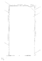
- Fig. 1 shows a double door consisting of door leaf 1 and door frame 2.
- Door leaf 1 and Door frame 2 as shown in FIG. 2, are differentiated into closing side 3 and opening side 4.
- Door leaf 1 and frame 2 are mechanical via two non-standard multifunctional Connections 5 interconnected.
- the door leaf 1, as shown in FIG. 2, consists of a load-bearing frame 6, which on the closing side 3 and the opening side 4 is provided heat-conductive cover plates 7 made of aluminum.
- the cover plates 7 and the Door edges are provided with a cover layer 8 for decorative purposes.
- the door leaf has heat transfer elements instead of inserts on both sides 9, consisting of vertically running and arranged parallel to each other Copper pipes that end in header pipes that are thermally coupled each adjoin a cover plate but from each other by an insulating layer 10 Polyurethane foam are separated.
- the two heat exchanger elements 9 are hydraulically also usable separately.
- the two heat exchanger elements 9 are via the multifunctional connection 5 with the heat transfer system connected.
- In the upper part of the door frame penetrate in the door edge area Devices for venting 11 the heat exchanger the door frame.
- the door In the lower part the door are two emptying devices 12 for emptying the Heat exchanger integrated in the door frame.
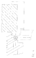
- the multifunctional Connection 5 consists of an upper part 13 which is attached to the door leaf 1 and the Lower part 14, which is attached to the frame. The attachment is done by means of the upper one Lappens 15
- the upper part 13 consists of the distributor sleeve 16 into which two connecting pipes 17, 18 open with the heat exchanger elements 9 of the opening 3 and closing side 4 are connected. Fitted in the upper part 13 is a loose hydraulic Switching sleeve 19.
- the switching sleeve 19 has bores 20 and arranged tangentially Elongated holes. Through these openings, the multifunctional connection 5 flowing heat transfer fluid either not or alternatively or simultaneously via the Distribution sleeve 16 with the heat exchangers 9 on the opening 3 and closing side 4 connected.
- the switching sleeve 19 is closed in the upper part and is in her Tapered diameter, sealed by a gland, upwards from the Distribution sleeve 16 led out.
- Fig. 4 shows shown at 90 ° open door leaf 1 that the switching sleeve 19 upwards is finally formed as an outer square 21.
- the outer square 21 is by a locking fork 22 fastened to the door frame 2 in one of several possible ways Held positions.
- the stuffing box seals off the upper part 13 in an upward direction.
- the distributor sleeve 16 is axially connected to a commercially available screw connection 23 and radially resilient liquid-flowable quick-release nipple 24 with valve connected.
- This quick coupling nipple 24 is detachable with a liquid flowable Quick coupling socket 25 connected.
- Upper part 13 and lower part 14 of the multifunctional Connection 5 are hydraulic by such a quick coupling 24; 25 connected.
- the quick coupling socket 25 is by means of screw 26 on the attached downward collecting sleeve 27 attached. The closed down The collecting sleeve 27 forms the lower part 14 with the lower fastening tab 28 the multifunctional connection 5 of door leaf 1 and frame 2. In the collecting sleeve 27 opens the connecting pipe 28 to the heat transfer distribution network.
- the arrangement and extension of the Openings in the switching sleeve 19 determine which side of the door (closing side 3, Opening side 4, both or neither of them) is flowed through by the heat transfer fluid.
- Fig. 5 shows the circuit options depending on the arrangement of the Bores in the switching sleeve 19 shown as cylinder developments of the switching sleeve for 90 ° door opening angle. Extend the effect to areas with larger opening angles is created by shaping the "door open" openings as elongated holes.
Landscapes
- Engineering & Computer Science (AREA)
- Physics & Mathematics (AREA)
- Thermal Sciences (AREA)
- Chemical & Material Sciences (AREA)
- Combustion & Propulsion (AREA)
- Mechanical Engineering (AREA)
- General Engineering & Computer Science (AREA)
- Building Environments (AREA)
- Furnace Housings, Linings, Walls, And Ceilings (AREA)
- Domestic Hot-Water Supply Systems And Details Of Heating Systems (AREA)
- Power-Operated Mechanisms For Wings (AREA)
Applications Claiming Priority (2)
| Application Number | Priority Date | Filing Date | Title |
|---|---|---|---|
| DE19820184A DE19820184C1 (de) | 1998-04-30 | 1998-04-30 | Tür mit integrierten Flächen zur Übertragung von Wärme |
| DE19820184 | 1998-04-30 |
Publications (3)
| Publication Number | Publication Date |
|---|---|
| EP0953809A2 true EP0953809A2 (fr) | 1999-11-03 |
| EP0953809A3 EP0953809A3 (fr) | 2001-10-24 |
| EP0953809B1 EP0953809B1 (fr) | 2004-06-30 |
Family
ID=7866823
Family Applications (1)
| Application Number | Title | Priority Date | Filing Date |
|---|---|---|---|
| EP99250133A Expired - Lifetime EP0953809B1 (fr) | 1998-04-30 | 1999-04-23 | Porte avec surfaces chauffantes integrées |
Country Status (3)
| Country | Link |
|---|---|
| EP (1) | EP0953809B1 (fr) |
| AT (1) | ATE270420T1 (fr) |
| DE (1) | DE19820184C1 (fr) |
Cited By (2)
| Publication number | Priority date | Publication date | Assignee | Title |
|---|---|---|---|---|
| FR2816042A1 (fr) * | 2000-10-30 | 2002-05-03 | Ghasnavi Eric Moavensadeh | Porte a eau chauffante |
| RU2378100C2 (ru) * | 2005-07-01 | 2010-01-10 | Кеярроу (Тайвань) Ко., Лтд | Многозвенная телескопическая крышка |
Families Citing this family (1)
| Publication number | Priority date | Publication date | Assignee | Title |
|---|---|---|---|---|
| DE102006012676A1 (de) * | 2006-03-20 | 2007-09-27 | Wolfgang Wendl | Vorrichtung zum Temperieren eines Raums |
Citations (2)
| Publication number | Priority date | Publication date | Assignee | Title |
|---|---|---|---|---|
| DE2617701A1 (de) | 1975-04-25 | 1976-11-04 | Elmetherm | Heizende tuer |
| DE9108666U1 (de) | 1991-07-15 | 1991-09-19 | ITP Institut für technische Beratung und Produktentwicklung GmbH, 6230 Frankfurt | Vorrichtung zur Beheizung von Räumen |
Family Cites Families (3)
| Publication number | Priority date | Publication date | Assignee | Title |
|---|---|---|---|---|
| FR2030520A5 (fr) * | 1969-04-25 | 1970-11-13 | Vey Jean Louis | |
| FR2085473A1 (fr) * | 1970-04-24 | 1971-12-24 | Vey Jean | Ensemble d'installation chauffage et climatisation |
| DE29604338U1 (de) * | 1996-03-08 | 1996-05-09 | Albers, Bernd, 44892 Bochum | Raumheizung |
-
1998
- 1998-04-30 DE DE19820184A patent/DE19820184C1/de not_active Expired - Fee Related
-
1999
- 1999-04-23 EP EP99250133A patent/EP0953809B1/fr not_active Expired - Lifetime
- 1999-04-23 AT AT99250133T patent/ATE270420T1/de not_active IP Right Cessation
Patent Citations (2)
| Publication number | Priority date | Publication date | Assignee | Title |
|---|---|---|---|---|
| DE2617701A1 (de) | 1975-04-25 | 1976-11-04 | Elmetherm | Heizende tuer |
| DE9108666U1 (de) | 1991-07-15 | 1991-09-19 | ITP Institut für technische Beratung und Produktentwicklung GmbH, 6230 Frankfurt | Vorrichtung zur Beheizung von Räumen |
Cited By (2)
| Publication number | Priority date | Publication date | Assignee | Title |
|---|---|---|---|---|
| FR2816042A1 (fr) * | 2000-10-30 | 2002-05-03 | Ghasnavi Eric Moavensadeh | Porte a eau chauffante |
| RU2378100C2 (ru) * | 2005-07-01 | 2010-01-10 | Кеярроу (Тайвань) Ко., Лтд | Многозвенная телескопическая крышка |
Also Published As
| Publication number | Publication date |
|---|---|
| EP0953809B1 (fr) | 2004-06-30 |
| EP0953809A3 (fr) | 2001-10-24 |
| ATE270420T1 (de) | 2004-07-15 |
| DE19820184C1 (de) | 1999-11-25 |
Similar Documents
| Publication | Publication Date | Title |
|---|---|---|
| EP1170553B1 (fr) | Plafond réfrigerant | |
| EP0882200B1 (fr) | Procede et dispositif de chauffage et de refroidissement de batiments, et revetement de murs thermo-isolant | |
| DE20203713U1 (de) | Vorrichtung in einem Gebäude zur Gewinnung von Wärmeenergie für eine Wärmepumpe | |
| DE19820184C1 (de) | Tür mit integrierten Flächen zur Übertragung von Wärme | |
| DE1804281C3 (de) | Anordnung zur Raumbeheizung oder .kühlung für den Einbau in Fensterumrahmungen o.dgl | |
| DE29922798U1 (de) | Vorrichtung zur Temperierung von Räumen | |
| DE102021118086A1 (de) | Haustechnikelement | |
| DE3802731C2 (fr) | ||
| DE2757193A1 (de) | Fassadenelement | |
| DE10015581C1 (de) | Innenraum-Klimatisierungsvorrichtung | |
| AT413756B (de) | Raumklimaeinrichtung | |
| WO2015043719A1 (fr) | Système de pose de fenêtres ou de portes | |
| DE2756860C3 (de) | Steuersystem fur die Heizungsanlage eines Mehrfamilienhauses | |
| EP1330579A1 (fr) | Batiment a faible consommation d'energie | |
| EP2792961B1 (fr) | Module d'échangeur de chaleur | |
| DE9116975U1 (de) | Anlage zum Heizen und/oder Kühlen eines Gebäudes mit Solarenergie unter Verwendung von transparenter Wärmedämmung | |
| DE3030536A1 (de) | Bruestungselement zum einbau in fassaden | |
| DE2708128A1 (de) | Fassadenelement fuer eine gebaeude- vorhangwand | |
| DE29617136U1 (de) | Gebäude mit einem Beheizungssystem | |
| DE19712744C1 (de) | Raumtemperierungssystem | |
| DE19738172C1 (de) | Einrichtung zum Temperieren von Gebäuden | |
| AT410456B (de) | Hochbau mit einer vielzahl von geschossen sowie profil mit metall | |
| DE102023202513A1 (de) | Heizeinrichtung sowie Verfahren und Bausatz zu deren Herstellung | |
| DE102006053355B4 (de) | Heiz- und Belüftungsvorrichtung | |
| DE3147632A1 (de) | Fassaden-absorber |
Legal Events
| Date | Code | Title | Description |
|---|---|---|---|
| PUAI | Public reference made under article 153(3) epc to a published international application that has entered the european phase |
Free format text: ORIGINAL CODE: 0009012 |
|
| AK | Designated contracting states |
Kind code of ref document: A2 Designated state(s): AT BE CH CY DE DK ES FI FR GB GR IE IT LI LU MC NL PT SE Kind code of ref document: A2 Designated state(s): AT BE CH FR GB IT LI NL |
|
| AX | Request for extension of the european patent |
Free format text: AL;LT;LV;MK;RO;SI |
|
| PUAL | Search report despatched |
Free format text: ORIGINAL CODE: 0009013 |
|
| AK | Designated contracting states |
Kind code of ref document: A3 Designated state(s): AT BE CH CY DE DK ES FI FR GB GR IE IT LI LU MC NL PT SE |
|
| AX | Request for extension of the european patent |
Free format text: AL;LT;LV;MK;RO;SI |
|
| 17P | Request for examination filed |
Effective date: 20020416 |
|
| AKX | Designation fees paid |
Free format text: AT BE CH CY DE DK ES LI |
|
| RBV | Designated contracting states (corrected) |
Designated state(s): AT BE CH FR GB IT LI NL |
|
| REG | Reference to a national code |
Ref country code: DE Ref legal event code: 8566 |
|
| GRAP | Despatch of communication of intention to grant a patent |
Free format text: ORIGINAL CODE: EPIDOSNIGR1 |
|
| GRAS | Grant fee paid |
Free format text: ORIGINAL CODE: EPIDOSNIGR3 |
|
| GRAA | (expected) grant |
Free format text: ORIGINAL CODE: 0009210 |
|
| AK | Designated contracting states |
Kind code of ref document: B1 Designated state(s): AT BE CH FR GB IT LI NL |
|
| REG | Reference to a national code |
Ref country code: GB Ref legal event code: FG4D Free format text: NOT ENGLISH Ref country code: CH Ref legal event code: EP |
|
| GBT | Gb: translation of ep patent filed (gb section 77(6)(a)/1977) |
Effective date: 20041019 |
|
| PG25 | Lapsed in a contracting state [announced via postgrant information from national office to epo] |
Ref country code: IT Free format text: LAPSE BECAUSE OF NON-PAYMENT OF DUE FEES;WARNING: LAPSES OF ITALIAN PATENTS WITH EFFECTIVE DATE BEFORE 2007 MAY HAVE OCCURRED AT ANY TIME BEFORE 2007. THE CORRECT EFFECTIVE DATE MAY BE DIFFERENT FROM THE ONE RECORDED. Effective date: 20050423 |
|
| PLBE | No opposition filed within time limit |
Free format text: ORIGINAL CODE: 0009261 |
|
| STAA | Information on the status of an ep patent application or granted ep patent |
Free format text: STATUS: NO OPPOSITION FILED WITHIN TIME LIMIT |
|
| ET | Fr: translation filed | ||
| 26N | No opposition filed |
Effective date: 20050331 |
|
| PUAJ | Public notification under rule 129 epc |
Free format text: ORIGINAL CODE: 0009425 |
|
| 32PN | Public notification | ||
| PGFP | Annual fee paid to national office [announced via postgrant information from national office to epo] |
Ref country code: AT Payment date: 20070420 Year of fee payment: 9 |
|
| PG25 | Lapsed in a contracting state [announced via postgrant information from national office to epo] |
Ref country code: AT Free format text: LAPSE BECAUSE OF NON-PAYMENT OF DUE FEES Effective date: 20080423 |
|
| PGFP | Annual fee paid to national office [announced via postgrant information from national office to epo] |
Ref country code: NL Payment date: 20090429 Year of fee payment: 11 Ref country code: FR Payment date: 20090429 Year of fee payment: 11 |
|
| PGFP | Annual fee paid to national office [announced via postgrant information from national office to epo] |
Ref country code: BE Payment date: 20090430 Year of fee payment: 11 |
|
| PGFP | Annual fee paid to national office [announced via postgrant information from national office to epo] |
Ref country code: CH Payment date: 20090430 Year of fee payment: 11 |
|
| PGFP | Annual fee paid to national office [announced via postgrant information from national office to epo] |
Ref country code: GB Payment date: 20090430 Year of fee payment: 11 |
|
| BERE | Be: lapsed |
Owner name: *SCHULZE-KARAL CHRISTIAN Effective date: 20100430 Owner name: *RODE BERNHARD Effective date: 20100430 |
|
| REG | Reference to a national code |
Ref country code: NL Ref legal event code: V1 Effective date: 20101101 |
|
| REG | Reference to a national code |
Ref country code: CH Ref legal event code: PL |
|
| GBPC | Gb: european patent ceased through non-payment of renewal fee |
Effective date: 20100423 |
|
| REG | Reference to a national code |
Ref country code: FR Ref legal event code: ST Effective date: 20101230 |
|
| PG25 | Lapsed in a contracting state [announced via postgrant information from national office to epo] |
Ref country code: NL Free format text: LAPSE BECAUSE OF NON-PAYMENT OF DUE FEES Effective date: 20101101 |
|
| PG25 | Lapsed in a contracting state [announced via postgrant information from national office to epo] |
Ref country code: LI Free format text: LAPSE BECAUSE OF NON-PAYMENT OF DUE FEES Effective date: 20100430 Ref country code: CH Free format text: LAPSE BECAUSE OF NON-PAYMENT OF DUE FEES Effective date: 20100430 |
|
| PG25 | Lapsed in a contracting state [announced via postgrant information from national office to epo] |
Ref country code: GB Free format text: LAPSE BECAUSE OF NON-PAYMENT OF DUE FEES Effective date: 20100423 Ref country code: BE Free format text: LAPSE BECAUSE OF NON-PAYMENT OF DUE FEES Effective date: 20100430 |
|
| PG25 | Lapsed in a contracting state [announced via postgrant information from national office to epo] |
Ref country code: FR Free format text: LAPSE BECAUSE OF NON-PAYMENT OF DUE FEES Effective date: 20100430 |