EP0952099A2 - Rückführungssystem für Robotergreifwerkzeug - Google Patents
Rückführungssystem für Robotergreifwerkzeug Download PDFInfo
- Publication number
- EP0952099A2 EP0952099A2 EP99250132A EP99250132A EP0952099A2 EP 0952099 A2 EP0952099 A2 EP 0952099A2 EP 99250132 A EP99250132 A EP 99250132A EP 99250132 A EP99250132 A EP 99250132A EP 0952099 A2 EP0952099 A2 EP 0952099A2
- Authority
- EP
- European Patent Office
- Prior art keywords
- article
- articles
- recirculating system
- reservoir
- cone
- Prior art date
- Legal status (The legal status is an assumption and is not a legal conclusion. Google has not performed a legal analysis and makes no representation as to the accuracy of the status listed.)
- Withdrawn
Links
Images


Classifications
-
- B—PERFORMING OPERATIONS; TRANSPORTING
- B65—CONVEYING; PACKING; STORING; HANDLING THIN OR FILAMENTARY MATERIAL
- B65G—TRANSPORT OR STORAGE DEVICES, e.g. CONVEYORS FOR LOADING OR TIPPING, SHOP CONVEYOR SYSTEMS OR PNEUMATIC TUBE CONVEYORS
- B65G47/00—Article or material-handling devices associated with conveyors; Methods employing such devices
- B65G47/02—Devices for feeding articles or materials to conveyors
- B65G47/04—Devices for feeding articles or materials to conveyors for feeding articles
- B65G47/12—Devices for feeding articles or materials to conveyors for feeding articles from disorderly-arranged article piles or from loose assemblages of articles
- B65G47/14—Devices for feeding articles or materials to conveyors for feeding articles from disorderly-arranged article piles or from loose assemblages of articles arranging or orientating the articles by mechanical or pneumatic means during feeding
- B65G47/1407—Devices for feeding articles or materials to conveyors for feeding articles from disorderly-arranged article piles or from loose assemblages of articles arranging or orientating the articles by mechanical or pneumatic means during feeding the articles being fed from a container, e.g. a bowl
- B65G47/1442—Devices for feeding articles or materials to conveyors for feeding articles from disorderly-arranged article piles or from loose assemblages of articles arranging or orientating the articles by mechanical or pneumatic means during feeding the articles being fed from a container, e.g. a bowl by means of movement of the bottom or a part of the wall of the container
- B65G47/1457—Rotating movement in the plane of the rotating part
-
- Y—GENERAL TAGGING OF NEW TECHNOLOGICAL DEVELOPMENTS; GENERAL TAGGING OF CROSS-SECTIONAL TECHNOLOGIES SPANNING OVER SEVERAL SECTIONS OF THE IPC; TECHNICAL SUBJECTS COVERED BY FORMER USPC CROSS-REFERENCE ART COLLECTIONS [XRACs] AND DIGESTS
- Y10—TECHNICAL SUBJECTS COVERED BY FORMER USPC
- Y10S—TECHNICAL SUBJECTS COVERED BY FORMER USPC CROSS-REFERENCE ART COLLECTIONS [XRACs] AND DIGESTS
- Y10S209/00—Classifying, separating, and assorting solids
- Y10S209/919—Rotary feed conveyor
Definitions
- the present invention relates to a device for receiving parts in bulk which are bunched together, and redistributing the parts into separate units which may be effectively handled by a picker-type robot utilizing a vision system or sensor means to discriminate the individual parts.
- the present invention provides a recirculating device including a reservoir which receives parts in bulk that are bunched together.
- a cone-shaped rotating disk surrounds the reservoir and receives the parts and redistributes the parts into separate units.
- the parts are delivered to an inner periphery of the cone of the cone-shaped disk, and the parts then slide down the inclined slope of the cone to an outer flat disk surrounding the cone.
- the parts slide down the rotating cone, they become spaced further apart due to the increase in radius of the outer periphery of the cone as compared with the radius of the inner periphery of the cone.
- the separated parts may then be effectively picked up off of the flat disk by a picker-type robot utilizing a vision system or sensor means to discriminate the individual parts.
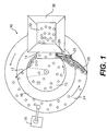
- a recirculating device 10 includes a central rotating feeder, or centrifugal feeder, as a reservoir 12. Parts are infed to the reservoir 12 from a prefilling device 14. The articles will go to the upper lip of a central rotating disc 15 in the reservoir 12 whereat they will be discharged to an inclined outer cone 16. A deflector 17 may be used to assist movement of the articles from the central rotating disc 15 to the cone 16. Due to the shape of the cone 16, the articles will slide down the cone 16 and spread out in a fan-shaped manner. This arrangement will enable the parts to spread out for subsequent handling by a robotic pickup device 18. The central rotating disc 15 and the outer surrounding cone 16 can be independently driven so as to rotate at the same or different speeds. Independent motors 20, 22 may be used as shown in Figure 7.
- the central rotating disc 15 rotates about an axis which is tilted with respect to vertical, whereas the cone 16 rotates about a vertical axis.
- the cone 16 and the flat disc 24 can be a one-piece unitary construction or can be molded together or can be two separate parts. Cracks should be avoided in the junction between the cone 16 and the flat disc 24 in order to avoid catching parts when the cone 16 and flat disc 24 are made as two separate elements.
- the flat disc 24 is generally horizontal, it is contemplated that the flat disc 24 may be somewhat inclined.
- cone 16 and the flat disc 24 will be made of the same element and will therefore rotate simultaneously. Of course, these two elements could also rotate independently of one another if so desired.
- the flat disc 24 encircles the cone 16, and the cone 16 encircles the central rotating disc 15 which is the reservoir 12.
- the parts will be separated from one another.
- a quarter inch separation is usually the minimal separation needed for a vision system of a robotic pickup device 18. This vision system can spot different articles and then pick them up with the robotic device 18.
- a very slow speed of rotation or intermittent rotation can be utilized in order to accommodate the robotic device 18.
- One or more robotic devices 18 may be positioned adjacent the recirculation system 10 in order to pick up the parts from the flat disc 24. Parts will be overfed from the reservoir 12 down the cone 16 to the flat disc 24. In other words, it is contemplated that more parts than will be picked up by the robotic device 18 will be fed from the reservoir 12. The extra, non-picked up parts will be returned to the reservoir 12 by a return mechanism as will be described below.
- the vision system of the robotic device 18 can reject these parts (i.e., simply not pick them up). Because the system overfeeds parts, then an adequate supply of parts is always available for the robotic device 18 or devices.
- the flat disc 24 can be made from different materials. For example, if a vision system is used which requires the parts to back-lighted, the flat disc 24 can be transparent or opaque which easily lets light pass therethrough. As can be seen in Figure 7, there is no drive system beneath the flat disc 24. Because the flat disc 24 is connected or formed integrally with the cone 16, it is the cone 16 that is driven. Therefore the area beneath the flat disc 24 is free of any obstructions. A light source or a plurality of light sources can be provided in the area adjacent the robotic device 18 beneath the flat disc 24. Light from this light source can shine upwardly through the flat disc 24 to provide proper illumination for the vision system of the robotic pick up device 18.
- this flat disc 24 can have a circular strip provided therethrough which is transparent while the remainder of the flat disc 24 is solid or non-transparent.
- windows can be provided in the flat disc 24 in order to enable light to pass therethrough.
- the articles can be illuminated from a light source above or adjacent to the robotic device 18.
- the light would shine from the light source downwardly onto the flat disc 24 and parts thereon. This light would then reflect upwardly to the vision system of the robotic device 18.
- the flat disc 24 can be made from a dark material to enhance operation of the vision system for the robotic device 18.
- the flat disc 24 could be made from or coated with a fluorescent material. This would enhance operation of the vision system.
- a return mechanism 25 is provided for feeding parts back to the reservoir 12. These parts can be extra parts which have been overfed from the reservoir 12, can be parts which are improperly oriented and therefore rejected by the vision system of the robotic device 18, or simply any other parts which remain on the rotating flat disc 24.
- the return mechanism 25 can include a scrapper device 26 which moves the articles from the flat disc 24 to the edge of the cone 16. This scrapper device 26 can terminate at the cone 16 or can proceed up a portion of the cone 16 in order to move articles towards the reservoir 12. Because of the steepness of the cone 16, it is likely that a scraper device 26 alone would be insufficient. Therefore, a return belt conveyor 28 is provided.
- This return conveyor 28 will be at an angle relative to a radial line emanating from the center of the reservoir 12 as seen in Figure 1.
- the return conveyor 28 will be driven to move parts up the cone 16. At the top of the cone 16, the articles will simply fall back into the reservoir 12.
- a sensor device can be provided in the reservoir 12. When it is detected that an insufficient number of parts are provided in the reservoir 12, this will activate operation of the prefilling device 14.
- this prefilling device 14 can be bulk hopper 30 with a conveyor 32 which simply feeds articles to the reservoir 12. The articles will drop from the conveyor 32 into the reservoir 12 by gravity. This feeding is a trickle effect whereby articles are simply fed. Because it is not required to lift the articles from the bulk hopper 30 to the reservoir 12, the overall prefeeding arrangement can be simplified. However, it is possible to use a hopper which is below the height of reservoir 12 whereby a conveyor would be used to lift and drop articles into the reservoir 12. Other arrangements for filling the reservoir 12 are also contemplated.
- the straight inclined surface thereof shown in Figures 2 and 4-6 has a straight shape.
- a convex or concave inclined surface could be used, as shown in Figure 3.
- These different shapes can affect the spreading out of articles as they are fed from the reservoir 12 onto the flat disc 24 from the cone 16.
- contact with the scraper device 26 and/or conveyor belt 28 of the return mechanism which would overlie the concave cone 34 can be ensured. In other words, a gap beneath the conveyor 28 of the return mechanism will be avoided. This will prevent small parts from being trapped and ensure proper feed into the device.
- this gap may not be a problem and a straightshaped cone 16 or convex shaped cone can be used.
- the angle of the return conveyor belt 28 of the return mechanism relative to a radial line from the center of the reservoir 12 is such that the bottom of the conveyor belt 28 can be substantially flush with the upper surface of the cone 16. In this arrangement, the gap is prevented as noted above.
- the flat disc 24 can have an outer rim 36 if so desired.
- This outer rim 36 can be an integral one-piece structure with the flat disc 24.
- the cone 16, flat disc 24 and outer rim 36 can all be a one-piece construction, or these elements can be of different material. If the outer rim 36 is of a one-piece construction with the flat disc 24, then this outer rim 36 will obviously rotate simultaneously with rotation of the flat disc 24.
- a stationary outer rim could also be used if so desired. This stationary outer rim would be separate from the flat disc 24 and would serve to prevent articles from falling from the flat disc 24 as it rotates. Because the speed of the flat disc 24 is relatively slow, centrifugal forces are normally not a problem whereby the articles do not tend to roll from the flat disc 24. This slow rate of rotation is necessary when working with robotic devices 18.
- a stationary outer rim is provided, care should be taken that a gap between the stationary outer rim and the flat disc 24 is avoided in order to avoid catching parts therein.
- a small or minimal gap can be of no consequence.
- the robotic device 18 can move the article horizontally from the flat disc 24 rather than having to lift the article.
- the stationary outer rim is broken in this section, the robotic device 18 need not lift the article over the stationary outer rim. This can simplify operation of the robotic device 18.
- the surface of the flat disc 24 can also be made rough or have suitable configuration in order to accommodate the articles being held. For example, if cylindrical articles will be handled, then grooves can be provided in the flat disc 24 such that the articles will not roll thereby making it easy for the robotic device 18 to pick them up. Other textures can be provided for the outer surface of the flat disc 24, such as a non-skid, sandpaper-like surface.
- the cone 16 on the other hand, is contemplated as having a flat smooth surface in order to allow parts to easily slide down its face.
- grooves for preorienting the parts or other texture can also be provided in the cone 16 as so desired. For example, if cylindrical parts are being handled, grooves can be provided in the cone 16 in order to preorient the parts in a desired direction.
Landscapes
- Engineering & Computer Science (AREA)
- Mechanical Engineering (AREA)
- Feeding Of Articles To Conveyors (AREA)
Applications Claiming Priority (2)
| Application Number | Priority Date | Filing Date | Title |
|---|---|---|---|
| US8273198P | 1998-04-23 | 1998-04-23 | |
| US82731P | 1998-04-23 |
Publications (2)
| Publication Number | Publication Date |
|---|---|
| EP0952099A2 true EP0952099A2 (de) | 1999-10-27 |
| EP0952099A3 EP0952099A3 (de) | 2000-10-11 |
Family
ID=22173075
Family Applications (1)
| Application Number | Title | Priority Date | Filing Date |
|---|---|---|---|
| EP99250132A Withdrawn EP0952099A3 (de) | 1998-04-23 | 1999-04-23 | Rückführungssystem für Robotergreifwerkzeug |
Country Status (2)
| Country | Link |
|---|---|
| US (1) | US6311825B1 (de) |
| EP (1) | EP0952099A3 (de) |
Cited By (5)
| Publication number | Priority date | Publication date | Assignee | Title |
|---|---|---|---|---|
| WO2002003412A1 (en) * | 2000-06-30 | 2002-01-10 | General Electric Company | Electrode tip loading method and apparatus |
| EP2392527A1 (de) * | 2010-06-01 | 2011-12-07 | ZBV-Automation Berse + Elsas GmbH | Vereinzelungsvorrichtung |
| FR3043076A1 (fr) * | 2015-11-02 | 2017-05-05 | Expertise Vision | Dispositif d'individualisation d'objets en vrac de petite taille |
| WO2022106738A1 (es) * | 2020-11-23 | 2022-05-27 | Posimat, Sa | Máquina para orientar y alinear artículos alimentados a granel |
| CN115108282A (zh) * | 2021-03-19 | 2022-09-27 | 第一实业威视博株式会社 | 排列装置 |
Families Citing this family (14)
| Publication number | Priority date | Publication date | Assignee | Title |
|---|---|---|---|---|
| US20060083419A1 (en) * | 2004-10-18 | 2006-04-20 | Michael Carbaugh | Systems and methods for isolating parts |
| FR2899884B1 (fr) * | 2006-04-12 | 2008-06-13 | Sidel Participations | Dispositif d'alimentation de preformes a grande cadence |
| US7669707B2 (en) * | 2006-06-29 | 2010-03-02 | Dunkley International, Inc. | Material handling apparatus with integrated part sorter |
| WO2008030937A2 (en) * | 2006-09-06 | 2008-03-13 | Curran Manufacturing Corporation | Rotary product accumulator |
| US20100063629A1 (en) * | 2008-09-10 | 2010-03-11 | Rixan Associates, Inc. | System and method for recirculating parts |
| IT1391349B1 (it) * | 2008-10-06 | 2011-12-13 | Ars S R L | Dispositivo alimentatore per robot, mezzi di automazione e simili. |
| US8684163B2 (en) * | 2012-06-01 | 2014-04-01 | Joseph Y. Ko | Destroying apparatus for electronic elements |
| JP5950876B2 (ja) * | 2013-07-25 | 2016-07-13 | 株式会社トーショー | 薬剤フィーダ |
| KR101689281B1 (ko) * | 2015-04-17 | 2016-12-27 | (주)엔클로니 | 정제 공급 장치 |
| JP2019135179A (ja) * | 2016-06-09 | 2019-08-15 | 三菱電機株式会社 | 部品供給装置 |
| JP6546215B2 (ja) * | 2017-05-19 | 2019-07-17 | ファナック株式会社 | 供給制御装置及び供給制御方法 |
| JP6496361B2 (ja) * | 2017-07-20 | 2019-04-03 | ファナック株式会社 | ワークを取出し装置に供給する供給装置および供給装置を備える搬送装置 |
| US10988324B2 (en) * | 2018-04-20 | 2021-04-27 | Greg Schombert | Food grade feeder device and system for rolls, sandwiches, odd shaped edibles and foodstuff |
| US12540031B2 (en) * | 2023-11-29 | 2026-02-03 | Optum, Inc. | Continuous motion systems and methods for automatic object loading and transportation |
Family Cites Families (10)
| Publication number | Priority date | Publication date | Assignee | Title |
|---|---|---|---|---|
| US4007854A (en) | 1975-10-08 | 1977-02-15 | Remington Arms Company, Inc. | Apparatus for feeding articles in serial order |
| JPS56161213A (en) * | 1980-05-15 | 1981-12-11 | Hanai Seisakusho:Kk | Hopper-equipped rotary parts feeder |
| US4453626A (en) * | 1980-12-29 | 1984-06-12 | The Arthur G. Russell Company, Incorporated | Vibratory feeding apparatus |
| JPS5997862A (ja) * | 1982-11-24 | 1984-06-05 | 株式会社日立製作所 | 部品供給装置 |
| IT1220297B (it) * | 1988-02-25 | 1990-06-15 | Gd Spa | Dispositivo selezionatore di caramelle |
| JP2640374B2 (ja) * | 1989-03-01 | 1997-08-13 | テンチ機械 株式会社 | 菓子片の整列分離装置 |
| US5299675A (en) * | 1990-11-09 | 1994-04-05 | T L Feeding Systems, Inc. | Pouch feeder method and device with angled rim |
| US5474493A (en) * | 1995-01-12 | 1995-12-12 | Roger D. Pugh | Apparatus for placing randomly deposited items in a single file |
| JP3530612B2 (ja) * | 1995-03-01 | 2004-05-24 | 靜甲株式会社 | 物品供給装置 |
| US5853078A (en) * | 1998-02-13 | 1998-12-29 | Menziken Automation, Inc. | Vibrating feeder bowl with annular rotating disk feeder |
-
1999
- 1999-04-23 EP EP99250132A patent/EP0952099A3/de not_active Withdrawn
- 1999-04-23 US US09/296,407 patent/US6311825B1/en not_active Expired - Fee Related
Cited By (11)
| Publication number | Priority date | Publication date | Assignee | Title |
|---|---|---|---|---|
| WO2002003412A1 (en) * | 2000-06-30 | 2002-01-10 | General Electric Company | Electrode tip loading method and apparatus |
| US6446783B1 (en) | 2000-06-30 | 2002-09-10 | General Electric Company | Electrode tip loading method and apparatus |
| EP2392527A1 (de) * | 2010-06-01 | 2011-12-07 | ZBV-Automation Berse + Elsas GmbH | Vereinzelungsvorrichtung |
| FR3043076A1 (fr) * | 2015-11-02 | 2017-05-05 | Expertise Vision | Dispositif d'individualisation d'objets en vrac de petite taille |
| WO2017076779A1 (fr) * | 2015-11-02 | 2017-05-11 | Expertise Vision | Dispositif d'individualisation d'objets en vrac de petite taille |
| WO2022106738A1 (es) * | 2020-11-23 | 2022-05-27 | Posimat, Sa | Máquina para orientar y alinear artículos alimentados a granel |
| CN116457291A (zh) * | 2020-11-23 | 2023-07-18 | 波西玛特公司 | 用于对散装供应的物品进行定向和对齐的机器 |
| EP4249410A4 (de) * | 2020-11-23 | 2024-05-22 | Posimat, SA | Maschine zum ausrichten und ausrichten von in schüttgut zugeführten gegenständen |
| US12180013B2 (en) | 2020-11-23 | 2024-12-31 | Posimat, Sa | Machine for orienting and aligning articles supplied in bulk |
| CN116457291B (zh) * | 2020-11-23 | 2026-03-31 | 波西玛特公司 | 用于对散装供应的物品进行定向和对齐的机器 |
| CN115108282A (zh) * | 2021-03-19 | 2022-09-27 | 第一实业威视博株式会社 | 排列装置 |
Also Published As
| Publication number | Publication date |
|---|---|
| EP0952099A3 (de) | 2000-10-11 |
| US6311825B1 (en) | 2001-11-06 |
Similar Documents
| Publication | Publication Date | Title |
|---|---|---|
| US6311825B1 (en) | Recirculation system for a robotic pickup | |
| AU658755B2 (en) | Machine for automatically positioning and aligning containers | |
| CN1020573C (zh) | 一种用于将容器自动定位和输入的装置 | |
| CN110121325A (zh) | 药物供给器 | |
| US4830172A (en) | Rotary feeder | |
| JPH07504772A (ja) | 2個のディスクを有するコイン取扱装置 | |
| US3672485A (en) | Egg collecting apparatus | |
| US4673077A (en) | Article supply apparatus | |
| MXPA02009447A (es) | Maquina lineal automatica orientadora y alineadora de articulos. | |
| US3599829A (en) | Hopper-type apparatus for orienting and feeding bottle and jar caps, or the like | |
| US12180013B2 (en) | Machine for orienting and aligning articles supplied in bulk | |
| JP2002508290A (ja) | 製品の選別装置を供給するための、製品、特に果実の搬送装置 | |
| JP3530612B2 (ja) | 物品供給装置 | |
| CA2721141C (en) | An apparatus and method for feeding used objects | |
| EP0679342B1 (de) | Vorrichtung zum Vereinzeln und Aufgeben einer Frucht aus Massenzufuhr | |
| US5954184A (en) | Apparatus and method for feeding, presenting and/or orienting parts | |
| JP3420569B2 (ja) | 部品の自動分配及び配向機構 | |
| US20050155842A1 (en) | Unit and method for reordering confectionery products, such as sweets and similar | |
| US5806654A (en) | Rotating singulator | |
| GB2184105A (en) | Rotary feeder | |
| JPH07163946A (ja) | サイズ選別機 | |
| JPH0664736A (ja) | 部品類供給方法及び装置 | |
| US4934982A (en) | Apparatus for the individual separation of disk-shaped items, in particular coins | |
| US4729755A (en) | Elevator for delicate articles | |
| JP3869495B2 (ja) | 球状農作物搬出装置 |
Legal Events
| Date | Code | Title | Description |
|---|---|---|---|
| PUAI | Public reference made under article 153(3) epc to a published international application that has entered the european phase |
Free format text: ORIGINAL CODE: 0009012 |
|
| AK | Designated contracting states |
Kind code of ref document: A2 Designated state(s): DE ES NL |
|
| AX | Request for extension of the european patent |
Free format text: AL;LT;LV;MK;RO;SI |
|
| PUAL | Search report despatched |
Free format text: ORIGINAL CODE: 0009013 |
|
| AK | Designated contracting states |
Kind code of ref document: A3 Designated state(s): AT BE CH CY DE DK ES FI FR GB GR IE IT LI LU MC NL PT SE |
|
| AX | Request for extension of the european patent |
Free format text: AL;LT;LV;MK;RO;SI |
|
| 17P | Request for examination filed |
Effective date: 20010205 |
|
| 17Q | First examination report despatched |
Effective date: 20010326 |
|
| AKX | Designation fees paid |
Free format text: DE ES NL |
|
| GRAG | Despatch of communication of intention to grant |
Free format text: ORIGINAL CODE: EPIDOS AGRA |
|
| GRAG | Despatch of communication of intention to grant |
Free format text: ORIGINAL CODE: EPIDOS AGRA |
|
| GRAH | Despatch of communication of intention to grant a patent |
Free format text: ORIGINAL CODE: EPIDOS IGRA |
|
| STAA | Information on the status of an ep patent application or granted ep patent |
Free format text: STATUS: THE APPLICATION IS DEEMED TO BE WITHDRAWN |
|
| 18D | Application deemed to be withdrawn |
Effective date: 20030211 |