EP0951932B1 - Filter und Verfahren zu seiner Herstellung - Google Patents
Filter und Verfahren zu seiner Herstellung Download PDFInfo
- Publication number
- EP0951932B1 EP0951932B1 EP99850056A EP99850056A EP0951932B1 EP 0951932 B1 EP0951932 B1 EP 0951932B1 EP 99850056 A EP99850056 A EP 99850056A EP 99850056 A EP99850056 A EP 99850056A EP 0951932 B1 EP0951932 B1 EP 0951932B1
- Authority
- EP
- European Patent Office
- Prior art keywords
- filter
- distance
- connections
- bridges
- welded
- Prior art date
- Legal status (The legal status is an assumption and is not a legal conclusion. Google has not performed a legal analysis and makes no representation as to the accuracy of the status listed.)
- Expired - Lifetime
Links
- 238000000034 method Methods 0.000 title claims abstract description 13
- 238000004519 manufacturing process Methods 0.000 title abstract description 13
- 239000000463 material Substances 0.000 claims abstract description 68
- 238000003466 welding Methods 0.000 claims abstract description 26
- 238000002604 ultrasonography Methods 0.000 claims description 2
- 239000011888 foil Substances 0.000 description 4
- 230000006378 damage Effects 0.000 description 3
- 239000003292 glue Substances 0.000 description 2
- 238000009434 installation Methods 0.000 description 2
- 238000000926 separation method Methods 0.000 description 2
- 238000009958 sewing Methods 0.000 description 2
- 238000004026 adhesive bonding Methods 0.000 description 1
- 238000007664 blowing Methods 0.000 description 1
- 210000001520 comb Anatomy 0.000 description 1
- 238000005520 cutting process Methods 0.000 description 1
- 230000001419 dependent effect Effects 0.000 description 1
- 230000000694 effects Effects 0.000 description 1
- 239000000706 filtrate Substances 0.000 description 1
- 238000010438 heat treatment Methods 0.000 description 1
- 238000004064 recycling Methods 0.000 description 1
- 238000007493 shaping process Methods 0.000 description 1
- 238000003860 storage Methods 0.000 description 1
- 239000000126 substance Substances 0.000 description 1
Images


Classifications
-
- B—PERFORMING OPERATIONS; TRANSPORTING
- B01—PHYSICAL OR CHEMICAL PROCESSES OR APPARATUS IN GENERAL
- B01D—SEPARATION
- B01D46/00—Filters or filtering processes specially modified for separating dispersed particles from gases or vapours
- B01D46/52—Particle separators, e.g. dust precipitators, using filters embodying folded corrugated or wound sheet material
- B01D46/521—Particle separators, e.g. dust precipitators, using filters embodying folded corrugated or wound sheet material using folded, pleated material
-
- B—PERFORMING OPERATIONS; TRANSPORTING
- B01—PHYSICAL OR CHEMICAL PROCESSES OR APPARATUS IN GENERAL
- B01D—SEPARATION
- B01D46/00—Filters or filtering processes specially modified for separating dispersed particles from gases or vapours
- B01D46/0001—Making filtering elements
-
- B—PERFORMING OPERATIONS; TRANSPORTING
- B01—PHYSICAL OR CHEMICAL PROCESSES OR APPARATUS IN GENERAL
- B01D—SEPARATION
- B01D46/00—Filters or filtering processes specially modified for separating dispersed particles from gases or vapours
- B01D46/10—Particle separators, e.g. dust precipitators, using filter plates, sheets or pads having plane surfaces
-
- B—PERFORMING OPERATIONS; TRANSPORTING
- B01—PHYSICAL OR CHEMICAL PROCESSES OR APPARATUS IN GENERAL
- B01D—SEPARATION
- B01D2265/00—Casings, housings or mounting for filters specially adapted for separating dispersed particles from gases or vapours
- B01D2265/04—Permanent measures for connecting different parts of the filter, e.g. welding, glueing or moulding
-
- B—PERFORMING OPERATIONS; TRANSPORTING
- B01—PHYSICAL OR CHEMICAL PROCESSES OR APPARATUS IN GENERAL
- B01D—SEPARATION
- B01D2275/00—Filter media structures for filters specially adapted for separating dispersed particles from gases or vapours
- B01D2275/10—Multiple layers
-
- Y—GENERAL TAGGING OF NEW TECHNOLOGICAL DEVELOPMENTS; GENERAL TAGGING OF CROSS-SECTIONAL TECHNOLOGIES SPANNING OVER SEVERAL SECTIONS OF THE IPC; TECHNICAL SUBJECTS COVERED BY FORMER USPC CROSS-REFERENCE ART COLLECTIONS [XRACs] AND DIGESTS
- Y10—TECHNICAL SUBJECTS COVERED BY FORMER USPC
- Y10S—TECHNICAL SUBJECTS COVERED BY FORMER USPC CROSS-REFERENCE ART COLLECTIONS [XRACs] AND DIGESTS
- Y10S55/00—Gas separation
- Y10S55/05—Methods of making filter
Definitions
- the object of the invention is to achieve a filter and a fabrication method for this respectively that can be executed simpler, faster, and with a more complete homogeneity of material.
- the object of the invention is achieved by welding, between the opposed filter material sides of the filter bag, distance elements that then at the use of the filter can be extended to a different degree at different locations in the filter.
- the distance material can consist of sheet material with openings, for instance with a shape in principal corresponding to a ladder but where the separate steps from being entirely straight in one end of the distance element become increasingly bent or V-shaped towards the other end. Since the connecting steps are longer in one end the longitudinal parts of the ladder can be pulled apart to different degrees so that a narrowing or widening ladder is obtained, dependent on in which direction it is viewed.
- the material in the distance elements that are welded between the filter material may have the same chemical composition as the filter material but be constituted by a comparatively thin foil from which material has been punched so that bent, V-shaped or zigzag shaped foil bands are obtained as distances (also other shapes may give the same result).
- Sine the invented method allows continuous machine fabrication of filter bags by means of welding a good quality is obtained at a low cost and a minimum of manual work.
- the invention may also function with other types of binding, as for instance gluing, seams, heat treatment etc.
- the distance elements may have different shape as long as they at use result in the desired for instance differently long connections.
- the welding to the sides of the filter need not to be along lines but may instead be in points. If the number of cross connections that is required is small or if these should be widely spread the distance element sheets or the web may also include parts that via easily separable extra connections are connected to the parts that are to be welded to the filter material and thereby holds the distance material in the right position until its welded. When the welding has taken place the separable part may be drawn loose from the welded parts and removed from the filter.
- the distance elements can be of filter material, thin foil, net or a nonwoven material from which has been punched, cut, burnt or in some other way suitable connections with different lengths have been achieved.
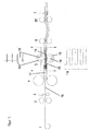
- fig 1 shows a machine for the fabrication of a filter in accordance with the invention
- fig 2 a detail of the machine and the fabrication respectively
- fig 3 a top view of a distance element according to the invention
- fig 4 a section through a finished filter
- fig 5 another embodiment of the distance element
- fig 6 an additional version of the distance element in accordance with the invention
- fig 7 how this is mounted
- fig 8 a cross section through the filter made in this way
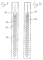
- amd fig 9 amd 10 two additional distance elements accoding to the invention.
- the filter material is fed from two rolls 4 towards a welding station 5. From an additional roll 1 distance element material of foil or sheet material is fed in between two rolls 2 that mill or punch away rectangular openings 10 (see fig 3), so that the distance material temporarily receives the shape of an endless net band constituted of longitudinal strips 8 and cross connections with intermediate openings 10. As an extension of the left edge of the cross connections a cut 11 extends a short distance (corresponding to slightly more than the width of the connection 9) into the strips 8. A subsequent punch 3 then cuts slots 12 in the strips 8 achieving an extension 13 of the cross connections 9 so that U-shaped connections are achieved between adjacent strips. By letting the punch cut differently deep differing total lengths for the U-shaped connections is achieved.
- the part of the distance material shown in fig 3 corresponds to a filter bag with long connections to the right adjacent to the opening of the filter.
- dollies 14 and 15 are arranged as is apparent from fig 1 and 2 above and below the distance material 16.
- the dollies have as is apparent from fig 1b the shape of crosswise arranged combs with broader openings between the teeth than these are broad and are relative each other displaced laterally (fig 2).
- the filter material 17 is fed past the dollies over and under these respectively.
- weld rolls 18 with flanges 19 are arranged.
- the flanges 19 of the rolls 18 as well as the "teeth" of the dollies are located corresponding to the longitudinal strips 8 of the distance material.
- the flanges 19 press the filter material 17. against the dollies 14 and 15 with the distance material therebetween. Ultra sound is fed to the rolls so that distance material and filter material is welded together along the strips 8.
- the connected material is drawn from the dollies, that so to say extends into the filter, further by rolls 6 t a combined separating and welding station 7 where the material step-wise is fed forwards by rolls 20 and is welded along the edges and also separated into individual bags. That is the welded bags are welded in the bottom at the same time as they are cut away from the upper end of the next filter bag.
- the filter bags are made with their openings turned in the running direction of the filter material during the fabrication either forwards or backwards depending on the orientation of the distance elements.
- FIG. 5 another distance element according to the invention is described constituted of longitudinal strips 28 connected with V-shaped cross connections 19.
- the V-shaped connections are differently sharply angled. In the part furthest down (in the filter fold or bag) the angle is very obtuse and consequently the length of the connection between the strips only slightly longer than the distance between the strips. With increasing distance upwards in the filter, that is upwards on the side, the angles become sharper, that is the length of the connections increase. This means that when the has been made the connections will constitute distance elements between the sides of the filter with increasing distance towards the opening side of the filter.
- the longitudinal strips run in the feed direction of the filter material and the distance material can be used in the installation described in connection with fig 1 and 2.
- bands 21 of distance element with a look corresponding to that shown in fig 6 is welded to opposite sides of the filter material 22, for instance by being bent to a half circular channel that is guided along a dolly 23 at the same time as welding takes place with two rolls 24.
- the cross connections 25 in the band then define the distance between the sides of the filter. This gives the appearance that is shown in fig 7 that is the distance connections are perpendicular to the filter material.
- bands 91 punched or cut as is shown in fig 9 may be used.
- cross connections 92 with different lengths are achieved due to different angles for the cuts 93. Since the cross connections 92 are connected to each other with a centrally arranged bridge 94 a much more stable strip is obtained much facilitating the machine mounting.
- the central connecting bridge can be used to contract the filter in the loser end of the filter. Since the filter in the upper end is forced open already by the mounting in a frame the upper cross connections will pull the central bridge upwards and if the connections in the lower end of the filter initially for instance are essentially straight this vertical pull upwards will reduce the width here pulling the sides of the filter closer together.
- the bridge or bridges In order to allow the vertical movement at straightening of the connections the bridge or bridges must be interrupted at top and bottom but still a far more controllable and more easily handled distance element is obtained, considerably facilitating fabrication.
- a longitudinal vertical slot is arranged allowing the separation of the edges of the band but without reduction of the stability. Furthermore small deviations in the vertical position of he distance band at mounting will not be critical.
- the distance element band that during the welding is pulled forwards is due to the continuous edges and stable bridging stable until the mounting has been completed and the distance element and filter material are cut into the individual filter bags.
- the invented method need not to include bands running in the length direction of the material webs but fixing can instead take place along bands that run transversely in relation to the material webs, preferably the welding or fixing is intermittent and does not need to be in the shape of a line but may even be arranged as points.
- the filter bags have to be arranged in the above described manner but instead one can consider letting the filter bags have their openings towards an edge of the webs. In this way it is even possible with simple machine mounting of bag lists or rims at the edges of the edges of the bags to be.
- the bridges or connections in the distance material is preferably shaped considering how the sides of the filter bags move at the separation from the position at fabrication to the position of mounting.
- connection making openings or special openings in this can be detected by for instance photo cells in order to synchronize the strip material with the welding of the filter bags.
Landscapes
- Chemical & Material Sciences (AREA)
- Chemical Kinetics & Catalysis (AREA)
- Filtering Materials (AREA)
- Filtering Of Dispersed Particles In Gases (AREA)
- Fluid-Pressure Circuits (AREA)
- Control Of Throttle Valves Provided In The Intake System Or In The Exhaust System (AREA)
- Centrifugal Separators (AREA)
- Separation Using Semi-Permeable Membranes (AREA)
Claims (11)
- Verfahren zum Herstellen von Verbindungen zwischen gegenüberliegenden Seiten einer Filterfalte oder eines Filterbeutels, dadurch gekennzeichnet, daß zwischen den gegenüberliegenden Seiten des Filtermaterials ein Distanzmaterial als ausgestanztes Material angeordnet ist, welches an Punkten oder längs Linien an den beiden Filtermaterialseiten derart angeschweißt ist, daß das Distanzmaterial an diesen Punkten oder Linien entweder an einer der Filterseiten oder an der anderen befestigt ist, und daß das Distanzmaterial Verbindungen oder Brücken zwischen den Teilen umfaßt, welche an verschiedenen Filterseiten angeschweißt sind, wobei die Brücken aus dem Distanzmaterial derart ausgestanzt sind, daß sie im Gebrauchszustand des Filters ausgestreckt werden können und im wesentlichen in Querrichtung verlaufende Distanzelemente bilden.
- Verfahren nach Anspruch 1, dadurch gekennzeichnet, daß die Verbindungen oder Brücken sich ändernde Längserstreckungen nach Maßgabe der Lage am Filter haben, so daß der Filterbeutel eine schmalere Kontur erhalten kann.
- Verfahren nach Anspruch 1 oder 2, dadurch gekennzeichnet, daß das Distanzelement längs abwechselnden Linien kontinuierlich in zwei Filtermaterialbahnen eingeschweißt wird, und daß dann in Längsrichtung eine Unterteilung in gesonderte Filter vorgenommen wird.
- Filter, welcher durch gegenüberliegende Seiten aus Filtermaterial gebildet wird, welche mittels dazwischen liegenden Distanzelementen aus einem Flächenmaterial zusammengehalten sind, das an die beiden Seiten des Filtermaterials eingeschweißt ist, dadurch gekennzeichnet, daß zwischen den Schweißpunkten Verbindungen angeordnet sind, welche gekrümmt oder abgewinkelt in der Ebene des Flächenmaterials ausgelegt sind, so daß sie im Gebrauchszustand des Filters gestreckt oder zur Erzielung einer größeren Längserstreckung als der Abstand zwischen den Schweißstellen an der Schweißnaht ausgefahren werden können.
- Filter nach Anspruch 4, dadurch gekennzeichnet, daß die Verbindungen unterschiedliche Längen haben, um einen schmalen Filterquerschnitt zu erhalten.
- Distanzelement zum Anschweißen an zwei gegenüberliegenden Filtermaterialflächen zur Herstellung einer Zwischenverbindung, dadurch gekennzeichnet, daß das Distanzelement gekrümmte oder abgewinkelte Brücken zwischen Befestigungspunkten an den verschiedenen Filterflächen umfaßt, so daß der Abstand zwischen den Filterflächen durch die Länge der ausgestreckten Brücken eingestellt wird.
- Distanzelement nach Anspruch 6, dadurch gekennzeichnet, daß es ein Flächenmaterial mit etwa demselben Flächenbereich wie die Abmessungen der Abmessung der Filterfalte oder des Beutels aufweist.
- Distanzelement nach Anspruch 6, dadurch gekennzeichnet, daß es Verbindungen oder Brücken mit unterschiedlichen Längen im ausgestreckten Zustand umfaßt, um schmalere Filterfalten oder Beutel zu bilden.
- Distanzelement dadurch gekennzeichnet, daß es von Streifen gebildet wird, die zwischen ihren beiden Längskanten mit Verbindungsbrücken mit unterschiedlichen Längen versehen sind, so daß die Distanzelemente eine schmale Filtergestalt ergeben, wenn sie an den gegenüberliegenden Rändern an den gegenüberliegenden Filterflächen eingeschweißt sind.
- Vorrichtung zur Durchführung eines Verfahrens nach Anspruch 1, dadurch gekennzeichnet, daß sie zwei kammähnliche Widerlager umfaßt, die relativ zueinander verschoben und derart angeordnet sind, daß ein Distanzelement zwischen denselben eingeführt werden kann, und daß auf jeder Seite des Paars von Widerlagern mit Flanschen versehene Rollen zum Schweißen beispielsweise mittels Ultraschall angeordnet sind, wobei zwischen den Widerlagern und den Rollen Filtermaterial zugeführt wird, welches an dem Distanzmaterial angeschweißt wird.
- Distanzelement, dadurch gekennzeichnet, daß es mit Querverbindungen mit unterschiedlichen Längserstreckungen versehen ist, und daß die Querverbindungen miteinander in größeren oder kleineren Gruppen durch eine oder mehrere Brücken verbunden sind, beispielsweise einer zentral angeordneten oder mehreren zur Erzielung eines symmetrischen Musters.
Priority Applications (1)
| Application Number | Priority Date | Filing Date | Title |
|---|---|---|---|
| DK99850056T DK0951932T3 (da) | 1998-04-09 | 1999-04-06 | Filter og fremgangsmåde til fremstilling af dette |
Applications Claiming Priority (2)
| Application Number | Priority Date | Filing Date | Title |
|---|---|---|---|
| SE9801249 | 1998-04-09 | ||
| SE9801249A SE522449C2 (sv) | 1998-04-09 | 1998-04-09 | Förfarande för åstadkommande av förbindningar mellan motsatta sidor i ett filterveck, filter med sådana förbindningar samt distanselement och anordning för genomförande av förfarandet |
Publications (3)
| Publication Number | Publication Date |
|---|---|
| EP0951932A2 EP0951932A2 (de) | 1999-10-27 |
| EP0951932A3 EP0951932A3 (de) | 2000-01-26 |
| EP0951932B1 true EP0951932B1 (de) | 2004-06-23 |
Family
ID=20410910
Family Applications (1)
| Application Number | Title | Priority Date | Filing Date |
|---|---|---|---|
| EP99850056A Expired - Lifetime EP0951932B1 (de) | 1998-04-09 | 1999-04-06 | Filter und Verfahren zu seiner Herstellung |
Country Status (8)
| Country | Link |
|---|---|
| US (1) | US6306188B1 (de) |
| EP (1) | EP0951932B1 (de) |
| AT (1) | ATE269753T1 (de) |
| DE (1) | DE69918213T2 (de) |
| DK (1) | DK0951932T3 (de) |
| MY (1) | MY123206A (de) |
| NO (1) | NO318667B1 (de) |
| SE (1) | SE522449C2 (de) |
Families Citing this family (2)
| Publication number | Priority date | Publication date | Assignee | Title |
|---|---|---|---|---|
| US8292981B2 (en) * | 2007-11-07 | 2012-10-23 | Oskar Air Products, Inc. | Low maintenance air cleaning system for welding chambers |
| US9700846B2 (en) * | 2014-12-05 | 2017-07-11 | Rorus Inc. | Fluid purification device with flexible housing |
Family Cites Families (7)
| Publication number | Priority date | Publication date | Assignee | Title |
|---|---|---|---|---|
| US5066319A (en) * | 1989-02-08 | 1991-11-19 | Lippold Hans Joachim | Filter cartridge |
| US5215609A (en) * | 1991-12-20 | 1993-06-01 | Sanders Scott L | Continuous process for producing ultrasonically welded air filters |
| US5156661A (en) * | 1992-01-31 | 1992-10-20 | Pall Corporation | Bag filter with thermoplastic tape-sealed sewn seam |
| DE4345122A1 (de) * | 1993-12-30 | 1995-07-06 | Detroit Holding Ltd | Verfahren zur Herstellung eines Filtereinsatzes |
| US5846360A (en) * | 1997-01-09 | 1998-12-08 | Gil; George | Filter and method and apparatus for manufacture thereof |
| US5928396A (en) * | 1997-12-31 | 1999-07-27 | Aaf International | Pocket filter and method and apparatus for making the same |
| US6010548A (en) * | 1998-01-30 | 2000-01-04 | Freudenberg Nonwovens Limited Partnership | Spaced pocket filter assembly and method of manufacturing same |
-
1998
- 1998-04-09 SE SE9801249A patent/SE522449C2/sv not_active IP Right Cessation
-
1999
- 1999-04-06 EP EP99850056A patent/EP0951932B1/de not_active Expired - Lifetime
- 1999-04-06 DK DK99850056T patent/DK0951932T3/da active
- 1999-04-06 AT AT99850056T patent/ATE269753T1/de not_active IP Right Cessation
- 1999-04-06 DE DE69918213T patent/DE69918213T2/de not_active Expired - Lifetime
- 1999-04-06 US US09/286,854 patent/US6306188B1/en not_active Expired - Lifetime
- 1999-04-08 MY MYPI99001354A patent/MY123206A/en unknown
- 1999-04-08 NO NO19991658A patent/NO318667B1/no not_active IP Right Cessation
Also Published As
| Publication number | Publication date |
|---|---|
| DK0951932T3 (da) | 2004-11-01 |
| DE69918213T2 (de) | 2005-06-30 |
| NO991658L (no) | 1999-10-11 |
| EP0951932A2 (de) | 1999-10-27 |
| SE9801249L (sv) | 1999-10-10 |
| NO991658D0 (no) | 1999-04-08 |
| SE522449C2 (sv) | 2004-02-10 |
| SE9801249D0 (sv) | 1998-04-09 |
| EP0951932A3 (de) | 2000-01-26 |
| ATE269753T1 (de) | 2004-07-15 |
| NO318667B1 (no) | 2005-04-25 |
| MY123206A (en) | 2006-05-31 |
| US6306188B1 (en) | 2001-10-23 |
| DE69918213D1 (de) | 2004-07-29 |
Similar Documents
| Publication | Publication Date | Title |
|---|---|---|
| DE60038639T2 (de) | Kunststofftasche | |
| US5496251A (en) | Method and apparatus for manufacturing a shell-shaped package, and such shell-shaped package | |
| DE3700914C2 (de) | ||
| EP0814890B1 (de) | Gasfiltersystem | |
| US20130031885A1 (en) | Pocket filter assembly | |
| CA2034867A1 (en) | Filter insert formed as a pleated pack and a process for its production | |
| DE3335551A1 (de) | Verfahren zur herstellung teilweise getrennter mehrfachbeuteln | |
| DE2354051C2 (de) | Vorrichtung zum Aufbringen von Reißbändchen auf eine laufende Verpackungsmaterialbahn | |
| DE69719287T2 (de) | Behälterträger | |
| DE1407932B2 (de) | Flache filtertasche mit hochkant gestelltem rechteckquerschnitt, und verfahren zu ihrer herstellung | |
| EP0951932A2 (de) | Filter und Verfahren zu seiner Herstellung | |
| US6159316A (en) | Method of making multi-pocket filter | |
| EP0348823B1 (de) | Verfahren und Vorrichtung zum Herstellen von Beuteln mit Zugbändern aus thermoplastischer Kunststoffolie | |
| EP0733010A1 (de) | Schlauchbeutelmaschine | |
| EP3159446A2 (de) | Vorrichtung zum thermischen behandeln einer textilen warenbahn | |
| DE1607668B2 (de) | Gasfilter | |
| JP2703504B2 (ja) | 流体処理用浸透フイルタの充填材およびその製造方法 | |
| FI108703B (fi) | Leikkauspöydän päällinen sekä menetelmä sen valmistamiseksi | |
| DE10021470A1 (de) | Schlauchbeutelverpackungsmaschine mit Querstreckmittel | |
| DE2712510A1 (de) | Verfahren und vorrichtung zur erzeugung von kunststoffbeuteln oder -saecken | |
| DE19829100C1 (de) | Faltenfilter | |
| US4945612A (en) | System and a method for joining the ends of a band-shaped elongate element | |
| US5151151A (en) | Pleating machine for dual fluted shade | |
| DE3742911C2 (de) | Verfahren und Vorrichtung zur Expandierung von Tabakmaterial | |
| GB2333249A (en) | Ultrasonically welded air filter element |
Legal Events
| Date | Code | Title | Description |
|---|---|---|---|
| PUAI | Public reference made under article 153(3) epc to a published international application that has entered the european phase |
Free format text: ORIGINAL CODE: 0009012 |
|
| AK | Designated contracting states |
Kind code of ref document: A2 Designated state(s): AT BE CH CY DE DK ES FI FR GB GR IE IT LI LU MC NL PT SE |
|
| AX | Request for extension of the european patent |
Free format text: AL;LT;LV;MK;RO;SI |
|
| PUAL | Search report despatched |
Free format text: ORIGINAL CODE: 0009013 |
|
| RIC1 | Information provided on ipc code assigned before grant |
Free format text: 7B 01D 46/06 A, 7B 01D 46/52 B, 7B 01D 29/07 B |
|
| AK | Designated contracting states |
Kind code of ref document: A3 Designated state(s): AT BE CH CY DE DK ES FI FR GB GR IE IT LI LU MC NL PT SE |
|
| AX | Request for extension of the european patent |
Free format text: AL;LT;LV;MK;RO;SI |
|
| 17P | Request for examination filed |
Effective date: 20000726 |
|
| AKX | Designation fees paid |
Free format text: AT BE CH CY DE DK ES FI FR GB GR IE IT LI LU MC NL PT SE |
|
| GRAP | Despatch of communication of intention to grant a patent |
Free format text: ORIGINAL CODE: EPIDOSNIGR1 |
|
| GRAS | Grant fee paid |
Free format text: ORIGINAL CODE: EPIDOSNIGR3 |
|
| GRAA | (expected) grant |
Free format text: ORIGINAL CODE: 0009210 |
|
| AK | Designated contracting states |
Kind code of ref document: B1 Designated state(s): AT BE CH CY DE DK ES FI FR GB GR IE IT LI LU MC NL PT SE |
|
| PG25 | Lapsed in a contracting state [announced via postgrant information from national office to epo] |
Ref country code: ES Free format text: LAPSE BECAUSE OF FAILURE TO SUBMIT A TRANSLATION OF THE DESCRIPTION OR TO PAY THE FEE WITHIN THE PRESCRIBED TIME-LIMIT Effective date: 20040623 Ref country code: AT Free format text: LAPSE BECAUSE OF FAILURE TO SUBMIT A TRANSLATION OF THE DESCRIPTION OR TO PAY THE FEE WITHIN THE PRESCRIBED TIME-LIMIT Effective date: 20040623 |
|
| REG | Reference to a national code |
Ref country code: GB Ref legal event code: FG4D |
|
| REG | Reference to a national code |
Ref country code: CH Ref legal event code: EP |
|
| REG | Reference to a national code |
Ref country code: IE Ref legal event code: FG4D |
|
| REF | Corresponds to: |
Ref document number: 69918213 Country of ref document: DE Date of ref document: 20040729 Kind code of ref document: P |
|
| PG25 | Lapsed in a contracting state [announced via postgrant information from national office to epo] |
Ref country code: SE Free format text: LAPSE BECAUSE OF FAILURE TO SUBMIT A TRANSLATION OF THE DESCRIPTION OR TO PAY THE FEE WITHIN THE PRESCRIBED TIME-LIMIT Effective date: 20040923 Ref country code: GR Free format text: LAPSE BECAUSE OF FAILURE TO SUBMIT A TRANSLATION OF THE DESCRIPTION OR TO PAY THE FEE WITHIN THE PRESCRIBED TIME-LIMIT Effective date: 20040923 |
|
| REG | Reference to a national code |
Ref country code: DK Ref legal event code: T3 |
|
| ET | Fr: translation filed | ||
| PG25 | Lapsed in a contracting state [announced via postgrant information from national office to epo] |
Ref country code: LU Free format text: LAPSE BECAUSE OF NON-PAYMENT OF DUE FEES Effective date: 20050406 Ref country code: CY Free format text: LAPSE BECAUSE OF FAILURE TO SUBMIT A TRANSLATION OF THE DESCRIPTION OR TO PAY THE FEE WITHIN THE PRESCRIBED TIME-LIMIT Effective date: 20050406 |
|
| PLBE | No opposition filed within time limit |
Free format text: ORIGINAL CODE: 0009261 |
|
| STAA | Information on the status of an ep patent application or granted ep patent |
Free format text: STATUS: NO OPPOSITION FILED WITHIN TIME LIMIT |
|
| PG25 | Lapsed in a contracting state [announced via postgrant information from national office to epo] |
Ref country code: MC Free format text: LAPSE BECAUSE OF NON-PAYMENT OF DUE FEES Effective date: 20050430 |
|
| 26N | No opposition filed |
Effective date: 20050324 |
|
| PG25 | Lapsed in a contracting state [announced via postgrant information from national office to epo] |
Ref country code: PT Free format text: LAPSE BECAUSE OF NON-PAYMENT OF DUE FEES Effective date: 20041123 |
|
| REG | Reference to a national code |
Ref country code: FR Ref legal event code: PLFP Year of fee payment: 18 |
|
| REG | Reference to a national code |
Ref country code: FR Ref legal event code: PLFP Year of fee payment: 19 |
|
| PGFP | Annual fee paid to national office [announced via postgrant information from national office to epo] |
Ref country code: NL Payment date: 20170419 Year of fee payment: 19 |
|
| PGFP | Annual fee paid to national office [announced via postgrant information from national office to epo] |
Ref country code: GB Payment date: 20170419 Year of fee payment: 19 Ref country code: DE Payment date: 20170419 Year of fee payment: 19 Ref country code: CH Payment date: 20170419 Year of fee payment: 19 Ref country code: FR Payment date: 20170419 Year of fee payment: 19 Ref country code: DK Payment date: 20170419 Year of fee payment: 19 Ref country code: IE Payment date: 20170421 Year of fee payment: 19 |
|
| PGFP | Annual fee paid to national office [announced via postgrant information from national office to epo] |
Ref country code: FI Payment date: 20170412 Year of fee payment: 19 Ref country code: IT Payment date: 20170420 Year of fee payment: 19 Ref country code: BE Payment date: 20170419 Year of fee payment: 19 |
|
| REG | Reference to a national code |
Ref country code: DE Ref legal event code: R119 Ref document number: 69918213 Country of ref document: DE |
|
| REG | Reference to a national code |
Ref country code: DK Ref legal event code: EBP Effective date: 20180430 |
|
| REG | Reference to a national code |
Ref country code: CH Ref legal event code: PL |
|
| REG | Reference to a national code |
Ref country code: NL Ref legal event code: MM Effective date: 20180501 |
|
| REG | Reference to a national code |
Ref country code: BE Ref legal event code: MM Effective date: 20180430 |
|
| GBPC | Gb: european patent ceased through non-payment of renewal fee |
Effective date: 20180406 |
|
| REG | Reference to a national code |
Ref country code: IE Ref legal event code: MM4A |
|
| PG25 | Lapsed in a contracting state [announced via postgrant information from national office to epo] |
Ref country code: NL Free format text: LAPSE BECAUSE OF NON-PAYMENT OF DUE FEES Effective date: 20180501 Ref country code: FI Free format text: LAPSE BECAUSE OF NON-PAYMENT OF DUE FEES Effective date: 20180406 Ref country code: DE Free format text: LAPSE BECAUSE OF NON-PAYMENT OF DUE FEES Effective date: 20181101 |
|
| PG25 | Lapsed in a contracting state [announced via postgrant information from national office to epo] |
Ref country code: LI Free format text: LAPSE BECAUSE OF NON-PAYMENT OF DUE FEES Effective date: 20180430 Ref country code: GB Free format text: LAPSE BECAUSE OF NON-PAYMENT OF DUE FEES Effective date: 20180406 Ref country code: CH Free format text: LAPSE BECAUSE OF NON-PAYMENT OF DUE FEES Effective date: 20180430 Ref country code: BE Free format text: LAPSE BECAUSE OF NON-PAYMENT OF DUE FEES Effective date: 20180430 |
|
| PG25 | Lapsed in a contracting state [announced via postgrant information from national office to epo] |
Ref country code: IT Free format text: LAPSE BECAUSE OF NON-PAYMENT OF DUE FEES Effective date: 20180406 Ref country code: IE Free format text: LAPSE BECAUSE OF NON-PAYMENT OF DUE FEES Effective date: 20180406 Ref country code: FR Free format text: LAPSE BECAUSE OF NON-PAYMENT OF DUE FEES Effective date: 20180430 |
|
| PG25 | Lapsed in a contracting state [announced via postgrant information from national office to epo] |
Ref country code: DK Free format text: LAPSE BECAUSE OF NON-PAYMENT OF DUE FEES Effective date: 20180430 |