EP0950789B1 - Torantrieb - Google Patents
Torantrieb Download PDFInfo
- Publication number
- EP0950789B1 EP0950789B1 EP99105809A EP99105809A EP0950789B1 EP 0950789 B1 EP0950789 B1 EP 0950789B1 EP 99105809 A EP99105809 A EP 99105809A EP 99105809 A EP99105809 A EP 99105809A EP 0950789 B1 EP0950789 B1 EP 0950789B1
- Authority
- EP
- European Patent Office
- Prior art keywords
- driver
- traction means
- door drive
- channel
- toothed belt
- Prior art date
- Legal status (The legal status is an assumption and is not a legal conclusion. Google has not performed a legal analysis and makes no representation as to the accuracy of the status listed.)
- Expired - Lifetime
Links
- 230000005540 biological transmission Effects 0.000 abstract 1
- 239000011324 bead Substances 0.000 description 3
- 238000004904 shortening Methods 0.000 description 3
- 238000010276 construction Methods 0.000 description 2
- 238000003780 insertion Methods 0.000 description 2
- 230000037431 insertion Effects 0.000 description 2
- 238000012423 maintenance Methods 0.000 description 2
- 238000000034 method Methods 0.000 description 2
- 241000282472 Canis lupus familiaris Species 0.000 description 1
- 229910000831 Steel Inorganic materials 0.000 description 1
- 229910052782 aluminium Inorganic materials 0.000 description 1
- XAGFODPZIPBFFR-UHFFFAOYSA-N aluminium Chemical compound [Al] XAGFODPZIPBFFR-UHFFFAOYSA-N 0.000 description 1
- 230000008878 coupling Effects 0.000 description 1
- 238000010168 coupling process Methods 0.000 description 1
- 238000005859 coupling reaction Methods 0.000 description 1
- 238000009434 installation Methods 0.000 description 1
- 230000002427 irreversible effect Effects 0.000 description 1
- 238000004519 manufacturing process Methods 0.000 description 1
- 229910052751 metal Inorganic materials 0.000 description 1
- 239000002184 metal Substances 0.000 description 1
- 239000007787 solid Substances 0.000 description 1
- 239000010959 steel Substances 0.000 description 1
- 210000002105 tongue Anatomy 0.000 description 1
- 230000001960 triggered effect Effects 0.000 description 1
Images

Classifications
-
- E—FIXED CONSTRUCTIONS
- E05—LOCKS; KEYS; WINDOW OR DOOR FITTINGS; SAFES
- E05F—DEVICES FOR MOVING WINGS INTO OPEN OR CLOSED POSITION; CHECKS FOR WINGS; WING FITTINGS NOT OTHERWISE PROVIDED FOR, CONCERNED WITH THE FUNCTIONING OF THE WING
- E05F15/00—Power-operated mechanisms for wings
- E05F15/60—Power-operated mechanisms for wings using electrical actuators
- E05F15/603—Power-operated mechanisms for wings using electrical actuators using rotary electromotors
- E05F15/665—Power-operated mechanisms for wings using electrical actuators using rotary electromotors for vertically-sliding wings
- E05F15/668—Power-operated mechanisms for wings using electrical actuators using rotary electromotors for vertically-sliding wings for overhead wings
- E05F15/681—Power-operated mechanisms for wings using electrical actuators using rotary electromotors for vertically-sliding wings for overhead wings operated by flexible elongated pulling elements, e.g. belts
-
- E—FIXED CONSTRUCTIONS
- E05—LOCKS; KEYS; WINDOW OR DOOR FITTINGS; SAFES
- E05Y—INDEXING SCHEME ASSOCIATED WITH SUBCLASSES E05D AND E05F, RELATING TO CONSTRUCTION ELEMENTS, ELECTRIC CONTROL, POWER SUPPLY, POWER SIGNAL OR TRANSMISSION, USER INTERFACES, MOUNTING OR COUPLING, DETAILS, ACCESSORIES, AUXILIARY OPERATIONS NOT OTHERWISE PROVIDED FOR, APPLICATION THEREOF
- E05Y2900/00—Application of doors, windows, wings or fittings thereof
- E05Y2900/10—Application of doors, windows, wings or fittings thereof for buildings or parts thereof
- E05Y2900/106—Application of doors, windows, wings or fittings thereof for buildings or parts thereof for garages
Definitions
- the invention relates to a door drive, in particular for Garage doors, with a traction mechanism, which is a drivable positive traction means with a plurality of transversely extending projections and one fixed to the traction means Has entrainment, the releasably with a in a running rail guided carriage is locked, with the gate can be coupled, wherein the traction means by means of a closure is designed as Endloszugstoff and the driver the Closure forms.
- Such door drives are, for example, from DE 76 30 475 U1 and DE 93 00 398 U1 known.
- the track is usually on the ceiling of a garage assembled.
- the carriage is, for example, by means of a rod with coupled to the garage door.
- the carriage is detachable with the Coupled with the driver.
- the traction mechanism is by means of a Motors, usually driven by an electric motor. Of the Motor is often carried out remotely controllable, so that the garage door drive can be triggered infrared or radio controlled.
- traction means are usually positive traction means, So in particular used timing belts and chains. For maintenance reasons The timing belts have prevailed nowadays.
- the timing belt is designed as an endless belt and two Guided deflection rollers, which are designed as a toothed belt pulleys are.
- the pulleys are at both ends of the track arranged.
- the one pulley is driven by the motor.
- the other role runs empty, but is usually mounted longitudinally displaceable on the running rail to the voltage To adjust the timing belt.
- the two free ends of the toothed belt are by means of a closure connected with each other.
- the closure is in all Usually an elongate element that has two tooth sections, in which the ends of the toothed belt can be inserted. To the placement of respective counterparts are the tooth sections squeezed with the timing belt.
- timing belt buckle is irreversible. Of the pinched part of the belt is not out of the shutter more solvable. Since usually a reaching over several teeth end section of the timing belt is squashed, it is after disconnecting the lock is no longer possible, the timing belt again to close again, so that the entire timing belt to committee becomes.
- the closure is in both cases with a central locking groove Mistake.
- the closure acts as a driver.
- releasable latch provided in the groove of the closure / driver engages, so that the closure / driver with the Carriage is locked.
- the locking takes place on Load span of the toothed belt. Rotary movements of the drive motor are thus in Lateralmonyen the carriage and thus implemented in gate movements.
- the lock is between dogs and Laufschlitten solvable, often one with the latch of the Carriage connected Bowden cable. In unlocked state
- the door can be opened independently of the drive motor and closed.
- the carriage is generally with two longitudinal channels for provide the load strand and the slack side of the toothed belt.
- Such garage door drives are also used as kits for Subsequent installation in garages sold. It is the Timing belts usually already in the locked state, ie as Endless toothed belt supplied. When the timing belt with the Time stretches, it is due to the nature of the above described Closure not possible to shorten the timing belt. Therefore either a jig with a very large stroke provided or the timing belt from time to time in total be replaced.
- the invention is based Problem is to provide a door drive, whose Traction means can be shortened by small amounts to expansions To balance the timing belt.
- the traction means laterally inserted into the channel is, as in conventional closures a positive connection be achieved between the driver and the traction means.
- the traction means by a division of the Pull means continue to introduce laterally into the channel.
- the form-fitting Traction means can thus "shortened” as a precaution, or even extended. These are shortenings or extensions in very small amounts possible. Insofar, a Tensioning mechanism provided with a relatively short stroke become. Even with larger strains of the belt must this not be exchanged altogether.
- a positive tension means Like a timing belt can shorten / lengthen each one To a tooth, for example, done with a chain to a member. Furthermore, such a driver is particularly easy to manufacture. It can be made in one piece in particular. It However, additional resources may be provided to prevent that the laterally introduced traction means back out of the Channel slides out.
- both end portions of the originally not closed Pull means laterally detachable in the channels of the driver insertable. On the one hand, this results in a more flexible Construction. Furthermore, the assembly is thereby facilitated.
- connection of the channels results during assembly a greater variability.
- Beilspielmik the one end section of the traction device further into the single formed Channel, the other end section for less far. This allows the relative position between during assembly Traction means and drivers are easily adjusted.
- the traction means a toothed belt is and if the driver has two tooth channels, in the End portions of the toothed belt are inserted laterally.
- Timing belts are particularly low maintenance. Dental channels can be easy to make. It is understood that the tooth channels a have the appropriate shape of the timing belt.
- timing belt can be simple and double-toothed belt be taken.
- HDT profile in the case of a generally flat belt across Belt extension project approximately semi-cylindrical projections.
- belt profile have the tooth channels according to a unilaterally smooth wall and opposite transverse and staggered semi-cylindrical Wells.
- one of Channels in relation to the length of the driver relatively long can be formed so that a comparatively large Surface for fixing the end portion of the traction means to the Driver is provided. Furthermore, this can also be done the safety of fixing the end sections of the traction device be increased at the driver.
- Through the turns of the channels acts in a tensile load one of the traction means on the Channel applied force component obliquely on a side wall of the canal.
- the traction means at Tensile loads in the positive connection is pressed. This can be achieved again that the channels are comparatively short can be trained.
- the channels are connected together, they can be connected in the top view of a side from which the timing belt laterally is introduced, a shape corresponding to a sine wave have.
- the provided by the driver Base area optimally utilized.
- a toothed belt as traction means is - a corresponding design of Channels of the driver provided - also advantageous that the teeth of the fixed in the channels end portions of the Toothed belt pressed in a tensile load in the wells become.
- the length of the channels in relation to Length of the driver can be increased.
- a "Timing belt reserve" in the closure (driver) added become.
- the traction means subsequently not only to shorten but also to extend.
- the driver as a slide is formed, which is parallel to the carriage at the Running track is movable.
- the measure to train the driver as a sled is regardless of the type of closure of the traction device as own invention considered.
- the driver has a channel for the Has empty strand of the traction means.
- the driver can be outermost be made comparatively easy. So can the driver in cross-section, for example, be substantially rectangular, so that he in a relatively simple rectangular profile of Running rail can be performed.
- the driver can with others Words are guided symmetrically on or in the track, so that it is largely excluded that the driver in the running rail jammed.
- means for clamping on the Driver can provide additional clamping means for the a roller can be dispensed with.
- a garage 10 shown in Fig. 1 is with a gate 12th locked.
- the gate 12 is designed as a tilt gate and is located with his Upper edge on the inside of the garage crash 18 at.
- the door drive 20 has a inward or outward direction the garage 10 longitudinally extending track 22, in which a carriage 24 is added.
- the carriage 24 is in the form of a coupling element a rod 26 with a bracket 28 at the top of the gate 12 hingedly attached to the inside.
- the running rail 22 In the end areas the running rail 22 are respectively deflection rollers 30 and 32 arranged, which are designed as a toothed belt pulleys. To the Pulleys 30, 32, runs here not shown Timing belt 44.
- the guide roller 30 at the rear end of the running rail 22 is with a drive 34 connected.
- the deflection roller 32 is over a not shown clamping mechanism longitudinally adjustable in the running rail 22 was added.
- the gate 12 In the position shown by solid lines in Fig. 1 the gate 12 is in the closed position. To the Opening the gate 12, the drive 34 is put into operation, whereby the deflection roller 30 is rotated. The timing belt 44, the around the pulleys 30 and 32 runs, is positively connected to the Carriage 24 connected, so that depending on the direction of rotation of the Carriage 24 is reciprocated in the track rail 22. Is the carriage 24 in the in Fig. 1 with the Reference numeral 24 'designated position, the tilting gate 12th open.
- the running rail 22 has a substantially inverted U-shaped profile.
- a U-base 22a is for attachment to the ceiling 16 of the garage 10 suitable. From the U-base 22a are symmetrical to one vertical symmetry axis 38 two U-legs 22b down in front.
- the carriage 24 is at its longitudinal sides with each a longitudinal groove provided for receiving the longitudinal webs 22c the running rail 22 are suitable. At the upper side Edges, the carriage 24 is further provided with recesses, adapted to an underside of the separating beads 22d and in Fig. 2 are not specified.
- the area between the U-base 22a and the upper edge of the Separating beads 22d is formed as a guide for a driver 36, whose function will be discussed below.
- the carriage 24 is thus along the track rail 22nd traversable. Furthermore, the trained as a sled Driver 36 along the longitudinal rail 22 movable, namely parallel to the carriage 24, such that a bottom the driver 36 in a plane just above a top of the carriage 24 is guided.
- the driver 36 is positively connected to the toothed belt 44, as explained below.
- the carriage 24 is about a unspecified safety bolt with coupled to the driver 36.
- the safety bolt can be from the Interior of the garage from mechanically loosen to the gate 12 of to decouple the drive 34, e.g. in case of power failure.
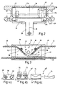
- Fig. 3 shows a view of the driver 36 in a view from underneath.
- the driver 36 has a generally designated 42 Holding section and a longitudinal channel 40 for the empty strand 46th of the toothed belt 44.
- the longitudinal channel 40 has continuous a cross section which is larger than the cross section of Toothed belt 44, so that the idler strand 46 free through the longitudinal channel 40 can pass.
- the holding portion 42 has two on one side to the bottom, so for visible in Fig. 3 side tooth channels 56, 58 for the end portions 52 and 54 of the toothed belt 44.
- the tooth channels 56, 58 have a shape such that the end portions 52 and 54 of the toothed belt 44 positively therein can be inserted. The insertion takes place from the Bottom of the driver 36 off.
- a tooth channel should in the present case such Can be understood in the channel with a strap or a chain a longitudinally non-uniform cross section so can be inserted, that a positive connection is achieved.
- the tooth channels 56, 58 are in the through the toothed belt 44th spanned plane in the driver 36 inwardly opposite the longitudinal extent of the load strand 48 bent. This will achieved that at a tensile load facing inward Teeth of the toothed belt 44 in the corresponding recesses of the Tooth channel 56 are pressed.
- the tooth channels 56, 58 are also connected to each other, so that in the view of Fig. 3, that is from below, the total so formed tooth channel assumes approximately the shape of a sine wave half. If the tooth channels 56, 58 are not connected to each other For example, they may be up to illustrated ends 60, 62 of the End portions 52, 54 of the toothed belt 44 extend. If the Toothed channels 56, 58 are connected to each other, they can either as shown in dashed lines in Fig. 3, by a Connecting portion to be connected to each other, also is designed as a tooth channel. Alternatively, the connection However, also "tooth-free" be formed.
- the puncture channel 64 can be described from the top of the Sine half-wave go out and parallel to the longitudinal extent extend the load strand 48; However, the puncture channel 64 could also continue parallel to the tooth channel 58.
- Timing belt When mounting the belt 44 is a greater length Timing belt first with an end portion, eg. 54, in the a toothed channel 58 is inserted. Subsequently, the free End around the pulleys 30, 32 led around. In connection then the timing belt 44 is cut to the appropriate length. Subsequently, the second end portion 52 in the second toothed channel 56 is inserted. The end sections 52, 54 are then secured in the tooth channels 56, 58, for example. by the screws 66.
- Fig. 4 shows schematically alternative embodiments of Carrier of the door drive according to the invention.
- FIG. 4a shows a driver 36 ', in which two channels 56', 58 ' are provided.
- the channel 58 ' may be similar to the tooth channel To be formed tooth channel 58 of FIG. 3, although he in FIG. 4a is shown tooth-free.
- the tooth channel 58 is the course of the tooth canal 58 'starting from a side edge the driver 36 'initially straight and then runs approximately over 270 ° on a circular line.
- the channel 56 ' is designed as a tooth-free channel, resembles in Layout, however, the tooth channel 58 '.
- a toothed belt pulley 70 rotatably mounted on the driver 36 '.
- the toothed belt pulley 70 serves for tensioning the toothed belt 44. To this The purpose is necessary, the rotational position of the pulley 70 with respect to the driver 36 'set by appropriate means.
- the driver 36 ' also has not one Longitudinal channel 40 for the backbone 46 of the toothed belt 44. With others Words is the slack side 46 of the belt 44 at this Embodiment laterally guided past the driver 36 '.
- FIG. 4b Another alternative embodiment of a driver 36 '' is shown in Fig. 4b.
- two channels 56 ", 58" are provided.
- the channels may be like the channels 56, 58 of the driver 36 Fig. 3 be open laterally. You can, however, alternatively also like a blind hole, starting from opposite ends 73 of the driver 36 '' be formed.
- the leading edges of the Sliders 72 can turn as a counter-profile to a toothed belt 44 be formed.
- teeth may be provided, according to the Art of a sprocket between the links of a chain.
- the driver 36 '' has similar to the driver 36 via a Longitudinal channel 40 '' for the slack side of the not shown Traction means.
- FIG. 4c An embodiment according to the invention of a driver 36 '' ' is shown in Fig. 4c.
- the driver 36 '' ' is formed in two parts, with a Basic element 74 and a tooth insert 76.
- the tooth insert 76th can be dimensioned so that the end portions 52, 54 of the Timing belt 44 between the base member 74 and the tooth insert 76 are compressed slightly. In that case you could do without additional securing means such as the screws 66.
- the tooth insert 76 could also be used with a horizontal protruding edge provided after insertion in the base member 74 which then formed tooth channels 56, 58th overlaps.
- the driver 76 is preferably made of plastic.
- the toothed belt 44 is preferably also a plastic toothed belt with a steel insert.
- the running rail 22 is made either of molded sheet metal or of an aluminum profile, that can be extruded, for example.
Landscapes
- Power-Operated Mechanisms For Wings (AREA)
- Belt Conveyors (AREA)
- Character Spaces And Line Spaces In Printers (AREA)
- Gates (AREA)
Description
- Fig. 1
- eine schematische Darstellung einer bevorzugten Ausführungsform des erfindungsgemäßen Torantriebes;
- Fig. 2
- eine schematische Schnittansicht entlang der Linie II-II von Fig. 1;
- Fig. 3
- eine Ansicht des in Fig. 2 gezeigten Mitnehmers von unten mit festgelegtem Zahnriemen; und
- Fig. 4a bis 4c
- schematisch alternative Ausführungsformen von Mitnehmern des erfindungsgemäßen Garagentorantriebes, woher die Ausführungsformen der Fig. 4a, 4b nicht zur Erfindung gehören.
Claims (8)
- Torantrieb, insbesondere für Garagentore (12), mit einem Zugmittelgetriebe (30, 32, 36, 44), das ein antreibbares formschlüssiges Zugmittel (44) mit einer Vielzahl von sich quer erstreckenden Vorsprüngen und einen an dem Zugmittel (44) festgelegten Mitnehmer (36) aufweist, der lösbar mit einem in einer Laufschiene (22) geführten Laufschlitten (24) verriegelt ist, der mit dem Tor (12) koppelbar ist, wobei das Zugmittel (44) mittels eines Verschlusses (50) als Endloszugmittel (44) ausgebildet ist und der Mitnehmer (36) den Verschluß (50) bildet,
dadurch gekennzeichnet, daß
der Mitnehmer (36) wenigstens einen Kanal (56, 58) aufweist, der entsprechend zu den Vorsprüngen des Zugmittels (44) Quervertiefungen aufweist und zur Seite hin offen ist und daß ein Ende des Zugmittels (44) seitlich in den Kanal (56, 58) lösbar eingeführt ist, wobei die zwei Endabschnitte (52, 54) des ursprünglich nicht geschlossenen Zugmittels (44) jeweils seitlich in zwei in dem Mitnehmer (36) vorgesehene Kanäle (56, 58) eingeführt sind, und wobei die Kanäle (56, 58) miteinander verbunden sind. - Torantrieb nach Anspruch 1, dadurch gekennzeichnet, daß das Zugmittel (44) ein Zahnriemen (44) ist und daß der Mitnehmer zwei Zahnkanäle (56,58) aufweist, in die die Endabschnitte (52, 54) des Zahnriemens (44) seitlich eingeführt sind.
- Torantrieb nach Anspruch 1 oder 2, dadurch gekennzeichnet, daß wenigstens einer der Kanäle (56, 58) gegenüber der Längserstreckung des Zugmittels (44) abgebogen ist.
- Torantrieb nach Anspruch 3, dadurch gekennzeichnet, daß der Kanal (56, 58) in der Ebene des Zugmittels (44) nach innen abgebogen ist.
- Torantrieb nach einem der Ansprüche 1 - 4, dadurch gekennzeichnet, daß sich die Kanäle (56, 58) überlappen.
- Torantrieb nach einem der Ansprüche 1 - 5, dadurch gekennzeichnet, daß der Mitnehmer (36) als Schlitten ausgebildet ist, der parallel zu dem Laufschlitten (24) an der Laufschiene (22) verfahrbar ist.
- Torantrieb nach einem der Ansprüche 1 - 6, dadurch gekennzeichnet, daß der Mitnehmer (36) einen Kanal (40) für das Leertrum (46) des Zugmittels (44) aufweist.
- Torantrieb nach einem der Ansprüche 1 - 7, dadurch gekennzeichnet, daß der Mitnehmer (36') Mittel (70) zum Spannen des Zugmittels (44) aufweist.
Applications Claiming Priority (2)
| Application Number | Priority Date | Filing Date | Title |
|---|---|---|---|
| DE19816564 | 1998-04-15 | ||
| DE19816564A DE19816564C1 (de) | 1998-04-15 | 1998-04-15 | Torantrieb |
Publications (3)
| Publication Number | Publication Date |
|---|---|
| EP0950789A2 EP0950789A2 (de) | 1999-10-20 |
| EP0950789A3 EP0950789A3 (de) | 2003-04-02 |
| EP0950789B1 true EP0950789B1 (de) | 2005-07-27 |
Family
ID=7864520
Family Applications (1)
| Application Number | Title | Priority Date | Filing Date |
|---|---|---|---|
| EP99105809A Expired - Lifetime EP0950789B1 (de) | 1998-04-15 | 1999-03-23 | Torantrieb |
Country Status (5)
| Country | Link |
|---|---|
| EP (1) | EP0950789B1 (de) |
| AT (1) | ATE300654T1 (de) |
| DE (1) | DE19816564C1 (de) |
| ES (1) | ES2246549T3 (de) |
| PT (1) | PT950789E (de) |
Families Citing this family (2)
| Publication number | Priority date | Publication date | Assignee | Title |
|---|---|---|---|---|
| DE19839110A1 (de) | 1998-08-27 | 2000-03-02 | Abon Antriebe Und Sicherheitss | Garagentorantrieb mit Führungsschlitten |
| DE10226303B4 (de) * | 2002-06-13 | 2013-06-27 | Novoferm Tormatic Gmbh | Antriebseinheit mit integrierter Halte- und Justiervorrichtung, insbesondere für ein Garagen- oder Sektionaltor, sowie ein Verfahren zur Montage einer integrierten Halte- und Justiervorrichtung für eine solche Antriebseinheit |
Family Cites Families (4)
| Publication number | Priority date | Publication date | Assignee | Title |
|---|---|---|---|---|
| DE7630475U1 (de) * | 1976-09-29 | 1978-08-17 | Siemens Ag, 1000 Berlin Und 8000 Muenchen | Vorrichtung zum oeffnen und schliessen von toren |
| DE9300398U1 (de) * | 1993-01-14 | 1993-02-25 | Robert Bosch Gmbh, 7000 Stuttgart | Antriebsvorrichtung für ein Torblatt |
| DE19635153C1 (de) * | 1996-08-30 | 1997-11-20 | Bosch Gmbh Robert | Torantriebsvorrichtung |
| WO1998013625A1 (de) * | 1996-09-26 | 1998-04-02 | Hörmann KG Antriebstechnik | Kupplung für zahngurte |
-
1998
- 1998-04-15 DE DE19816564A patent/DE19816564C1/de not_active Expired - Fee Related
-
1999
- 1999-03-23 EP EP99105809A patent/EP0950789B1/de not_active Expired - Lifetime
- 1999-03-23 AT AT99105809T patent/ATE300654T1/de not_active IP Right Cessation
- 1999-03-23 PT PT99105809T patent/PT950789E/pt unknown
- 1999-03-23 ES ES99105809T patent/ES2246549T3/es not_active Expired - Lifetime
Also Published As
| Publication number | Publication date |
|---|---|
| EP0950789A2 (de) | 1999-10-20 |
| DE19816564C1 (de) | 1999-07-29 |
| ES2246549T3 (es) | 2006-02-16 |
| EP0950789A3 (de) | 2003-04-02 |
| ATE300654T1 (de) | 2005-08-15 |
| PT950789E (pt) | 2005-09-30 |
Similar Documents
| Publication | Publication Date | Title |
|---|---|---|
| EP0708218B1 (de) | Einrichtung für die Ausführung des Schliess- und Öffnungsvorganges eines Kippfensters | |
| DE3811704A1 (de) | Antrieb fuer einen oeffnungsabschluss wie tor oder tuer aus gelenkig miteinander verbundenen lamellen | |
| DE3135401A1 (de) | Tor mit einer verriegelungseinrichtung | |
| DE3829922A1 (de) | Verbindung eines seilgetriebenen fensterhebemechanismus einer kraftfahrzeugtuer-fensterscheibe | |
| DE19544630C1 (de) | Bowdenrohr-Fensterheber mit Seillängenausgleich | |
| EP0764233B1 (de) | Rollo oder dergleichen | |
| DE10203904B4 (de) | Antriebsvorrichtung für Kraftfahrzeugschiebedächer | |
| EP1999331B1 (de) | Beschlag | |
| EP2050912A2 (de) | Schienenelement und Torantrieb | |
| DE19853989C1 (de) | Vorrichtung zum Öffnen und Verschliessen einer Öffnung in einer Wandung mittels einer Schiebetür | |
| DE19501230A1 (de) | Formschlüssige Antriebseinrichtung | |
| DE19629051A1 (de) | Fördersystem mit Greifklammern | |
| DE1683026C2 (de) | Lamellenjalousie | |
| DE2937121A1 (de) | Schiebedachantrieb | |
| DE10045804A1 (de) | Kraftfahrzeugfensterheber | |
| EP1061215B1 (de) | Getriebeanordnung für einen Stangenverschluss | |
| DE19816564C1 (de) | Torantrieb | |
| DE3127929A1 (de) | Eckumlenkung fuer treibstangenbeschlaege von fenstern und tueren od. dgl. | |
| DE19600949C2 (de) | Rolladen für Fenster oder Türen | |
| DE9114374U1 (de) | Treibstangenbeschlag für Fenster, Türen o.dgl. | |
| DE10138586A1 (de) | Führungsanordnung für einen Kraftfahrzeugfensterheber | |
| DE19816563C1 (de) | Torantrieb | |
| EP3235994B1 (de) | Antriebsvorrichtung für ein anzutreibendes element | |
| EP1071859B1 (de) | Schliessvorrichtung für flügelfenster und flügeltüren | |
| CH656428A5 (en) | Element-type lifting gate |
Legal Events
| Date | Code | Title | Description |
|---|---|---|---|
| PUAI | Public reference made under article 153(3) epc to a published international application that has entered the european phase |
Free format text: ORIGINAL CODE: 0009012 |
|
| AK | Designated contracting states |
Kind code of ref document: A2 Designated state(s): AT BE CH CY DE DK ES FI FR GB GR IE IT LI LU MC NL PT SE |
|
| AX | Request for extension of the european patent |
Free format text: AL;LT;LV;MK;RO;SI |
|
| RAP1 | Party data changed (applicant data changed or rights of an application transferred) |
Owner name: PRETTL, ROLF |
|
| PUAL | Search report despatched |
Free format text: ORIGINAL CODE: 0009013 |
|
| AK | Designated contracting states |
Kind code of ref document: A3 Designated state(s): AT BE CH CY DE DK ES FI FR GB GR IE IT LI LU MC NL PT SE Designated state(s): AT BE CH CY DE DK ES FI FR GB GR IE IT LI LU MC NL PT SE |
|
| AX | Request for extension of the european patent |
Extension state: AL LT LV MK RO SI |
|
| 17P | Request for examination filed |
Effective date: 20030926 |
|
| 17Q | First examination report despatched |
Effective date: 20031105 |
|
| AKX | Designation fees paid |
Designated state(s): AT BE CH CY DE DK ES FI FR GB GR IE IT LI LU MC NL PT SE |
|
| GRAP | Despatch of communication of intention to grant a patent |
Free format text: ORIGINAL CODE: EPIDOSNIGR1 |
|
| GRAS | Grant fee paid |
Free format text: ORIGINAL CODE: EPIDOSNIGR3 |
|
| GRAA | (expected) grant |
Free format text: ORIGINAL CODE: 0009210 |
|
| RBV | Designated contracting states (corrected) |
Designated state(s): AT BE CH CY DK ES FI FR GB GR IE IT LI LU MC NL PT SE |
|
| AK | Designated contracting states |
Kind code of ref document: B1 Designated state(s): AT BE CH CY DK ES FI FR GB GR IE IT LI LU MC NL PT SE |
|
| PG25 | Lapsed in a contracting state [announced via postgrant information from national office to epo] |
Ref country code: IE Free format text: LAPSE BECAUSE OF FAILURE TO SUBMIT A TRANSLATION OF THE DESCRIPTION OR TO PAY THE FEE WITHIN THE PRESCRIBED TIME-LIMIT Effective date: 20050727 Ref country code: FI Free format text: LAPSE BECAUSE OF FAILURE TO SUBMIT A TRANSLATION OF THE DESCRIPTION OR TO PAY THE FEE WITHIN THE PRESCRIBED TIME-LIMIT Effective date: 20050727 |
|
| REG | Reference to a national code |
Ref country code: GB Ref legal event code: FG4D Free format text: NOT ENGLISH |
|
| REG | Reference to a national code |
Ref country code: CH Ref legal event code: EP |
|
| REG | Reference to a national code |
Ref country code: IE Ref legal event code: FG4D Free format text: LANGUAGE OF EP DOCUMENT: GERMAN |
|
| REG | Reference to a national code |
Ref country code: DE Ref legal event code: 8566 |
|
| REG | Reference to a national code |
Ref country code: SE Ref legal event code: TRGR |
|
| REG | Reference to a national code |
Ref country code: PT Ref legal event code: SC4A Effective date: 20050802 |
|
| PG25 | Lapsed in a contracting state [announced via postgrant information from national office to epo] |
Ref country code: GR Free format text: LAPSE BECAUSE OF FAILURE TO SUBMIT A TRANSLATION OF THE DESCRIPTION OR TO PAY THE FEE WITHIN THE PRESCRIBED TIME-LIMIT Effective date: 20051027 Ref country code: DK Free format text: LAPSE BECAUSE OF FAILURE TO SUBMIT A TRANSLATION OF THE DESCRIPTION OR TO PAY THE FEE WITHIN THE PRESCRIBED TIME-LIMIT Effective date: 20051027 |
|
| GBT | Gb: translation of ep patent filed (gb section 77(6)(a)/1977) |
Effective date: 20051111 |
|
| REG | Reference to a national code |
Ref country code: ES Ref legal event code: FG2A Ref document number: 2246549 Country of ref document: ES Kind code of ref document: T3 |
|
| REG | Reference to a national code |
Ref country code: IE Ref legal event code: FD4D |
|
| PGFP | Annual fee paid to national office [announced via postgrant information from national office to epo] |
Ref country code: PT Payment date: 20060223 Year of fee payment: 8 |
|
| PGFP | Annual fee paid to national office [announced via postgrant information from national office to epo] |
Ref country code: FR Payment date: 20060313 Year of fee payment: 8 |
|
| PGFP | Annual fee paid to national office [announced via postgrant information from national office to epo] |
Ref country code: NL Payment date: 20060314 Year of fee payment: 8 |
|
| PGFP | Annual fee paid to national office [announced via postgrant information from national office to epo] |
Ref country code: AT Payment date: 20060315 Year of fee payment: 8 |
|
| PG25 | Lapsed in a contracting state [announced via postgrant information from national office to epo] |
Ref country code: MC Free format text: LAPSE BECAUSE OF NON-PAYMENT OF DUE FEES Effective date: 20060331 Ref country code: LU Free format text: LAPSE BECAUSE OF NON-PAYMENT OF DUE FEES Effective date: 20060331 Ref country code: LI Free format text: LAPSE BECAUSE OF NON-PAYMENT OF DUE FEES Effective date: 20060331 Ref country code: CH Free format text: LAPSE BECAUSE OF NON-PAYMENT OF DUE FEES Effective date: 20060331 |
|
| PGFP | Annual fee paid to national office [announced via postgrant information from national office to epo] |
Ref country code: BE Payment date: 20060331 Year of fee payment: 8 |
|
| ET | Fr: translation filed | ||
| PLBE | No opposition filed within time limit |
Free format text: ORIGINAL CODE: 0009261 |
|
| STAA | Information on the status of an ep patent application or granted ep patent |
Free format text: STATUS: NO OPPOSITION FILED WITHIN TIME LIMIT |
|
| 26N | No opposition filed |
Effective date: 20060428 |
|
| REG | Reference to a national code |
Ref country code: CH Ref legal event code: PL |
|
| PG25 | Lapsed in a contracting state [announced via postgrant information from national office to epo] |
Ref country code: SE Free format text: LAPSE BECAUSE OF NON-PAYMENT OF DUE FEES Effective date: 20070324 |
|
| PG25 | Lapsed in a contracting state [announced via postgrant information from national office to epo] |
Ref country code: PT Free format text: LAPSE BECAUSE OF NON-PAYMENT OF DUE FEES Effective date: 20070924 |
|
| REG | Reference to a national code |
Ref country code: PT Ref legal event code: MM4A Free format text: LAPSE DUE TO NON-PAYMENT OF FEES Effective date: 20070924 |
|
| EUG | Se: european patent has lapsed | ||
| PG25 | Lapsed in a contracting state [announced via postgrant information from national office to epo] |
Ref country code: AT Free format text: LAPSE BECAUSE OF NON-PAYMENT OF DUE FEES Effective date: 20070323 |
|
| GBPC | Gb: european patent ceased through non-payment of renewal fee |
Effective date: 20070323 |
|
| NLV4 | Nl: lapsed or anulled due to non-payment of the annual fee |
Effective date: 20071001 |
|
| BERE | Be: lapsed |
Owner name: *PRETTL ROLF Effective date: 20070331 |
|
| PG25 | Lapsed in a contracting state [announced via postgrant information from national office to epo] |
Ref country code: BE Free format text: LAPSE BECAUSE OF NON-PAYMENT OF DUE FEES Effective date: 20070331 |
|
| REG | Reference to a national code |
Ref country code: FR Ref legal event code: ST Effective date: 20071130 |
|
| PG25 | Lapsed in a contracting state [announced via postgrant information from national office to epo] |
Ref country code: NL Free format text: LAPSE BECAUSE OF NON-PAYMENT OF DUE FEES Effective date: 20071001 |
|
| PGFP | Annual fee paid to national office [announced via postgrant information from national office to epo] |
Ref country code: SE Payment date: 20060314 Year of fee payment: 8 |
|
| PG25 | Lapsed in a contracting state [announced via postgrant information from national office to epo] |
Ref country code: GB Free format text: LAPSE BECAUSE OF NON-PAYMENT OF DUE FEES Effective date: 20070323 |
|
| PGFP | Annual fee paid to national office [announced via postgrant information from national office to epo] |
Ref country code: IT Payment date: 20080326 Year of fee payment: 10 |
|
| PG25 | Lapsed in a contracting state [announced via postgrant information from national office to epo] |
Ref country code: FR Free format text: LAPSE BECAUSE OF NON-PAYMENT OF DUE FEES Effective date: 20070402 |
|
| PGFP | Annual fee paid to national office [announced via postgrant information from national office to epo] |
Ref country code: GB Payment date: 20060322 Year of fee payment: 8 |
|
| PG25 | Lapsed in a contracting state [announced via postgrant information from national office to epo] |
Ref country code: CY Free format text: LAPSE BECAUSE OF FAILURE TO SUBMIT A TRANSLATION OF THE DESCRIPTION OR TO PAY THE FEE WITHIN THE PRESCRIBED TIME-LIMIT Effective date: 20050727 |
|
| PGFP | Annual fee paid to national office [announced via postgrant information from national office to epo] |
Ref country code: ES Payment date: 20090821 Year of fee payment: 11 |
|
| PG25 | Lapsed in a contracting state [announced via postgrant information from national office to epo] |
Ref country code: IT Free format text: LAPSE BECAUSE OF NON-PAYMENT OF DUE FEES Effective date: 20090323 |
|
| REG | Reference to a national code |
Ref country code: ES Ref legal event code: FD2A Effective date: 20110419 |
|
| PG25 | Lapsed in a contracting state [announced via postgrant information from national office to epo] |
Ref country code: ES Free format text: LAPSE BECAUSE OF NON-PAYMENT OF DUE FEES Effective date: 20110404 |
|
| PG25 | Lapsed in a contracting state [announced via postgrant information from national office to epo] |
Ref country code: ES Free format text: LAPSE BECAUSE OF NON-PAYMENT OF DUE FEES Effective date: 20100324 |