EP0950425A2 - Tubes pour la micro-chirurgie et procédés de fabrication - Google Patents
Tubes pour la micro-chirurgie et procédés de fabrication Download PDFInfo
- Publication number
- EP0950425A2 EP0950425A2 EP99302205A EP99302205A EP0950425A2 EP 0950425 A2 EP0950425 A2 EP 0950425A2 EP 99302205 A EP99302205 A EP 99302205A EP 99302205 A EP99302205 A EP 99302205A EP 0950425 A2 EP0950425 A2 EP 0950425A2
- Authority
- EP
- European Patent Office
- Prior art keywords
- inner layer
- thickness
- reduced
- catheter
- region
- Prior art date
- Legal status (The legal status is an assumption and is not a legal conclusion. Google has not performed a legal analysis and makes no representation as to the accuracy of the status listed.)
- Withdrawn
Links
Images
Classifications
-
- A—HUMAN NECESSITIES
- A61—MEDICAL OR VETERINARY SCIENCE; HYGIENE
- A61M—DEVICES FOR INTRODUCING MEDIA INTO, OR ONTO, THE BODY; DEVICES FOR TRANSDUCING BODY MEDIA OR FOR TAKING MEDIA FROM THE BODY; DEVICES FOR PRODUCING OR ENDING SLEEP OR STUPOR
- A61M25/00—Catheters; Hollow probes
- A61M25/0009—Making of catheters or other medical or surgical tubes
-
- F—MECHANICAL ENGINEERING; LIGHTING; HEATING; WEAPONS; BLASTING
- F16—ENGINEERING ELEMENTS AND UNITS; GENERAL MEASURES FOR PRODUCING AND MAINTAINING EFFECTIVE FUNCTIONING OF MACHINES OR INSTALLATIONS; THERMAL INSULATION IN GENERAL
- F16L—PIPES; JOINTS OR FITTINGS FOR PIPES; SUPPORTS FOR PIPES, CABLES OR PROTECTIVE TUBING; MEANS FOR THERMAL INSULATION IN GENERAL
- F16L11/00—Hoses, i.e. flexible pipes
- F16L11/20—Double-walled hoses, i.e. two concentric hoses
-
- A—HUMAN NECESSITIES
- A61—MEDICAL OR VETERINARY SCIENCE; HYGIENE
- A61M—DEVICES FOR INTRODUCING MEDIA INTO, OR ONTO, THE BODY; DEVICES FOR TRANSDUCING BODY MEDIA OR FOR TAKING MEDIA FROM THE BODY; DEVICES FOR PRODUCING OR ENDING SLEEP OR STUPOR
- A61M25/00—Catheters; Hollow probes
- A61M25/0043—Catheters; Hollow probes characterised by structural features
- A61M25/0045—Catheters; Hollow probes characterised by structural features multi-layered, e.g. coated
-
- A—HUMAN NECESSITIES
- A61—MEDICAL OR VETERINARY SCIENCE; HYGIENE
- A61M—DEVICES FOR INTRODUCING MEDIA INTO, OR ONTO, THE BODY; DEVICES FOR TRANSDUCING BODY MEDIA OR FOR TAKING MEDIA FROM THE BODY; DEVICES FOR PRODUCING OR ENDING SLEEP OR STUPOR
- A61M25/00—Catheters; Hollow probes
- A61M25/0043—Catheters; Hollow probes characterised by structural features
- A61M25/0054—Catheters; Hollow probes characterised by structural features with regions for increasing flexibility
-
- B—PERFORMING OPERATIONS; TRANSPORTING
- B29—WORKING OF PLASTICS; WORKING OF SUBSTANCES IN A PLASTIC STATE IN GENERAL
- B29L—INDEXING SCHEME ASSOCIATED WITH SUBCLASS B29C, RELATING TO PARTICULAR ARTICLES
- B29L2031/00—Other particular articles
- B29L2031/753—Medical equipment; Accessories therefor
- B29L2031/7542—Catheters
Definitions
- This invention relates to methods of making medico-surgical tubes.
- the invention is more particularly concerned with tubes with a soft tip, and with methods of manufacture of such tubes.
- a method of making a medico-surgical tube characterised in that a tubular member is formed by continuously co-extruding an inner layer and an outer layer, that the thickness of the extruded inner layer is periodically reduced to form regions along the tubing of reduced thickness, and that the tubing is cut at the regions to form tubes with an end region of reduced stiffness.
- the thickness of the inner layer is preferably reduced by increasing its internal diameter.
- the thickness of the inner layer may be reduced along the region such that the stiffness varies along the region.
- the thickness of the inner layer is preferably reduced to zero along a part at least of the region.
- the material of the inner layer is preferably stiffer than the material of the outer layer.
- the cut end of the tubing including the region of reduced thickness may be end formed and a side opening formed close to the closed end.
- the catheter 1 is about 75-100cm long with a rounded tip at its patient end 2 and a side opening 3 close to the tip.
- the machine end 4 of the catheter 1 is open and cut square for attachment to a conventional epidural connector, not shown.
- the wall 10 of the catheter 1 is extruded from a thermoplastics material.
- the wall 10 has an inner layer 11 and an outer layer 12 of different materials, the inner layer 11 being of a stiffer material than the outer layer 12.
- Both layers 11 and 12 may be of the same polymer, such as PVC, but with differing amounts of plasticizer, or the layers could be of different polymers, such as an outer layer of PVC and an inner layer of ABS, nylon or polycarbonate.
- the reduced thickness of the inner layer 11 along the region 13 makes this more flexible than the remainder of the catheter 1, and the tip 2, with no inner layer, is relatively soft. This reduces the risk of damage to the dura and enables the forward end of the catheter 1 to bend to conform to the shape of the epidural space with a reduced risk of kinking. Because the inner layer 11 is stiffer than the outer layer 12, it can be relatively thin and still provide sufficient rigidity to the main part of the catheter. This ensures that the inner diameter of the catheter 1 is kept as large as possible. Reducing the thickness of the inner layer 11, even to a zero thickness, does not greatly affect the overall thickness of the wall of the catheter 1 so that it still presents a relatively smooth internal surface.
- the stepped change in wall thickness along the region 13 gives a more gradual change in stiffness and thereby ensures that the catheter curves gradually if it is bent at its patient end.
- the inner layer could be gradually reduced in thickness along the region at the patient end.
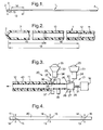
- the extrusion machine 20 has two extrusion heads 21 and 22 for extruding the inner and outer layers 11 and 12 respectively.
- the rear extrusion head 21 has a conventional hopper 23 and heated extruder screw 24 for supplying the harder plastics material 25 used in the inner layer 11 in molten form to an extrusion die 26.
- the extrusion die 26 comprises a fixed outer ring 27 having a circular passage 28 defining the outer diameter of the inner layer 11, the passage tapering slightly to a smaller diameter at its forwards, left-hand end.
- the die 26 also includes a solid inner cone 29 the outside surface of which defines the internal diameter of the inner layer 11.
- the outer surface of the cone 29 is tapered parallel with the taper on the passage 28 through the outer ring 27 and the cone projects into the ring so that an annular space 30 is defined between the two components, which defines the outlet orifice of the die 26.
- the inner cone 29 is connected by a coupling 31 to an actuator control 32 operable to displace the cone axially in either direction.
- an actuator control 32 operable to displace the cone axially in either direction.
- the forward extrusion head 22 has a conventional hopper 33 and heated extruder screw 34 for supplying the softer plastics material 35 used in the outer layer 12 in molten form to an extrusion die 36.
- the extrusion die 36 comprises a fixed outer ring 37 and a fixed inner ring 38.
- the inner ring 38 has an aperture of the same diameter as the external diameter of the inner layer 11 so that the ring closely embraces the inner layer as it emerges from the rear extrusion head 21.
- the outer ring 37 has a circular aperture with a larger diameter equal to the external diameter of the tube 1.
- a pin 39 may be located between the outer and inner rings 37 and 38 to provide a small diameter lumen within the thickness of the outer layer 12. such as for inflating a cuff.
- the forward extrusion head 22 therefore, extrudes the softer outer layer 12 directly on top of the harder inner layer 11 so that composite two-layer tubing 40 emerges continuously from the machine 20, as shown in Figure 4, which shows the diameter of the tubing to an exaggerated scale.
- the actuator 32 is operated such that the cone 29 is periodically displaced forward to reduce the thickness of the inner layer 11 to about half its usual thickness for a distance of about 13mm and is then displaced fully forwards to reduce the thickness to zero for about 12mm. It is then opened fully to its usual position.
- the tubing 40 emerging from the machine 20 will have an inner layer 11 of full thickness along most of its length but interrupted periodically by regions 13 of reduced thickness.
- the tubing 40 is cut into lengths at the right-hand end of the regions 13 of reduced thickness, which provides the patient end 2 of the finished catheters 1. The cut lengths of tube are then end formed and the side openings are made in the usual way to form the finished catheters 1.
- the method of making the catheter 1 enables a soft patient end tip to be provided as a continuous process without the need for subsequent assembly operations.
- the invention is not confined to epidural catheters but could be used to provide a tip of reduced stiffness to other tubes such as endotracheal tubes.
- the catheter could be reinforced such as by incorporating a helical reinforcing element, or a braid into the outer layer.
- a lumen could be formed along the outer layer for various conventional purposes.
Landscapes
- Engineering & Computer Science (AREA)
- Health & Medical Sciences (AREA)
- Life Sciences & Earth Sciences (AREA)
- General Engineering & Computer Science (AREA)
- Biomedical Technology (AREA)
- Biophysics (AREA)
- Pulmonology (AREA)
- Anesthesiology (AREA)
- Mechanical Engineering (AREA)
- Heart & Thoracic Surgery (AREA)
- Hematology (AREA)
- Animal Behavior & Ethology (AREA)
- General Health & Medical Sciences (AREA)
- Public Health (AREA)
- Veterinary Medicine (AREA)
- Media Introduction/Drainage Providing Device (AREA)
- Extrusion Moulding Of Plastics Or The Like (AREA)
Applications Claiming Priority (2)
| Application Number | Priority Date | Filing Date | Title |
|---|---|---|---|
| GB9807856 | 1998-04-15 | ||
| GBGB9807856.1A GB9807856D0 (en) | 1998-04-15 | 1998-04-15 | Medico-surgical tubes and methods of manufacture |
Publications (2)
| Publication Number | Publication Date |
|---|---|
| EP0950425A2 true EP0950425A2 (fr) | 1999-10-20 |
| EP0950425A3 EP0950425A3 (fr) | 1999-11-17 |
Family
ID=10830279
Family Applications (1)
| Application Number | Title | Priority Date | Filing Date |
|---|---|---|---|
| EP99302205A Withdrawn EP0950425A3 (fr) | 1998-04-15 | 1999-03-22 | Tubes pour la micro-chirurgie et procédés de fabrication |
Country Status (4)
| Country | Link |
|---|---|
| EP (1) | EP0950425A3 (fr) |
| JP (1) | JPH11319105A (fr) |
| AU (1) | AU2367299A (fr) |
| GB (1) | GB9807856D0 (fr) |
Cited By (3)
| Publication number | Priority date | Publication date | Assignee | Title |
|---|---|---|---|---|
| DE20110121U1 (de) * | 2001-06-19 | 2002-12-05 | Braun Melsungen Ag | Katheter |
| EP2520412A1 (fr) * | 2011-05-02 | 2012-11-07 | Astra Tech AB | Procédé pour la fabrication d'un objet tubulaire pour l'insertion dans une voie de passage corporelle |
| US10076435B2 (en) | 2015-02-25 | 2018-09-18 | Cook Medical Technologies Llc | Stent deployment system with overmolded tip |
Families Citing this family (2)
| Publication number | Priority date | Publication date | Assignee | Title |
|---|---|---|---|---|
| JP2003102827A (ja) * | 2001-09-28 | 2003-04-08 | Terumo Corp | 医療用チューブ |
| DE102017206154A1 (de) * | 2017-04-11 | 2018-10-11 | B. Braun Melsungen Ag | Schlauchleitung und Verfahren zu deren Herstellung |
Citations (1)
| Publication number | Priority date | Publication date | Assignee | Title |
|---|---|---|---|---|
| WO1994001160A1 (fr) | 1992-07-14 | 1994-01-20 | Arrow International Investment Corporation | Catheter epidural a double durometre en une seule piece |
Family Cites Families (3)
| Publication number | Priority date | Publication date | Assignee | Title |
|---|---|---|---|---|
| US4596563A (en) * | 1983-06-09 | 1986-06-24 | Cordis Corporation | Thin-walled multi-layered catheter having a fuseless tip |
| US5125913A (en) * | 1990-05-11 | 1992-06-30 | Fbk International Corporation | Soft-tipped catheters |
| DE4032869A1 (de) * | 1990-10-17 | 1992-04-23 | Gercke Hans Hermann | Verfahren zur herstellung von kathetern |
-
1998
- 1998-04-15 GB GBGB9807856.1A patent/GB9807856D0/en not_active Ceased
-
1999
- 1999-03-22 EP EP99302205A patent/EP0950425A3/fr not_active Withdrawn
- 1999-04-12 AU AU23672/99A patent/AU2367299A/en not_active Abandoned
- 1999-04-14 JP JP11106476A patent/JPH11319105A/ja active Pending
Patent Citations (1)
| Publication number | Priority date | Publication date | Assignee | Title |
|---|---|---|---|---|
| WO1994001160A1 (fr) | 1992-07-14 | 1994-01-20 | Arrow International Investment Corporation | Catheter epidural a double durometre en une seule piece |
Cited By (9)
| Publication number | Priority date | Publication date | Assignee | Title |
|---|---|---|---|---|
| DE20110121U1 (de) * | 2001-06-19 | 2002-12-05 | Braun Melsungen Ag | Katheter |
| EP2520412A1 (fr) * | 2011-05-02 | 2012-11-07 | Astra Tech AB | Procédé pour la fabrication d'un objet tubulaire pour l'insertion dans une voie de passage corporelle |
| WO2012150251A1 (fr) * | 2011-05-02 | 2012-11-08 | Astra Tech Ab | Procédé de fabrication d'un objet tubulaire destiné à être inséré dans un passage corporel |
| EP2965891A1 (fr) * | 2011-05-02 | 2016-01-13 | Dentsply IH AB | Procédé pour la fabrication d'un objet tubulaire destiné à être inséré dans une voie de passage corporelle |
| US9352504B2 (en) | 2011-05-02 | 2016-05-31 | Dentsply International Inc. | Method for manufacturing of a tubular object for insertion into a body passageway |
| AU2012251696B2 (en) * | 2011-05-02 | 2016-07-21 | Dentsply Ih Ab | Method for manufacturing of a tubular object for insertion into a body passageway |
| US10076435B2 (en) | 2015-02-25 | 2018-09-18 | Cook Medical Technologies Llc | Stent deployment system with overmolded tip |
| US10716693B2 (en) | 2015-02-25 | 2020-07-21 | Cook Medical Technologies Llc | Stent deployment system with overmolded tip |
| US10806618B2 (en) | 2015-02-25 | 2020-10-20 | Cook Medical Technologies Llc | Stent deployment system with overmolded tip |
Also Published As
| Publication number | Publication date |
|---|---|
| EP0950425A3 (fr) | 1999-11-17 |
| GB9807856D0 (en) | 1998-06-10 |
| AU2367299A (en) | 1999-10-28 |
| JPH11319105A (ja) | 1999-11-24 |
Similar Documents
| Publication | Publication Date | Title |
|---|---|---|
| US5125913A (en) | Soft-tipped catheters | |
| US5868718A (en) | Process to form dimensionally variable tubular members for use in catheter procedures | |
| US6135992A (en) | Medical catheter | |
| US4842590A (en) | Catheter and method for making | |
| US4330497A (en) | Method of making grooved plastic medical tubing | |
| US5456674A (en) | Catheters with variable properties | |
| EP1401630B1 (fr) | Dispositif medical a element extrude presentant une orientation helicoidale | |
| US11491304B2 (en) | Extrusion with preferential bend axis | |
| US7638087B2 (en) | Medico-surgical tubes and methods of manufacture | |
| EP0950425A2 (fr) | Tubes pour la micro-chirurgie et procédés de fabrication | |
| US6673291B1 (en) | Methods of manufacturing medico-surgical tubes | |
| JPH0928808A (ja) | 二重チューブ及び二重チューブを用いたバルーンカテーテル | |
| GB2336338A (en) | Manufacture of a catheter by co-extrusion | |
| JPH09313613A (ja) | 拡張体付カテーテル | |
| CA2270829C (fr) | Tubes medico-chirurgicaux et leurs methodes de fabrication | |
| WO2017037404A1 (fr) | Canules internes et ensemble tube pour trachéostomie | |
| CA2347024C (fr) | Tubes et procede pour leur fabrication | |
| JP3977116B2 (ja) | ガイドチューブの製造方法 | |
| JP3310601B2 (ja) | 断面形状可変押出成形用ダイ機構 | |
| JP2006314476A (ja) | カテーテル、およびその成形装置 | |
| JPH09327516A (ja) | バルーンカテーテル |
Legal Events
| Date | Code | Title | Description |
|---|---|---|---|
| PUAI | Public reference made under article 153(3) epc to a published international application that has entered the european phase |
Free format text: ORIGINAL CODE: 0009012 |
|
| PUAL | Search report despatched |
Free format text: ORIGINAL CODE: 0009013 |
|
| AK | Designated contracting states |
Kind code of ref document: A2 Designated state(s): DE FR GB IE IT |
|
| AX | Request for extension of the european patent |
Free format text: AL;LT;LV;MK;RO;SI |
|
| AK | Designated contracting states |
Kind code of ref document: A3 Designated state(s): AT BE CH CY DE DK ES FI FR GB GR IE IT LI LU MC NL PT SE |
|
| AX | Request for extension of the european patent |
Free format text: AL;LT;LV;MK;RO;SI |
|
| RIC1 | Information provided on ipc code assigned before grant |
Free format text: 6A 61M 25/00 A, 6F 16L 11/20 B |
|
| 17P | Request for examination filed |
Effective date: 20000316 |
|
| AKX | Designation fees paid |
Free format text: DE FR GB IE IT |
|
| STAA | Information on the status of an ep patent application or granted ep patent |
Free format text: STATUS: THE APPLICATION IS DEEMED TO BE WITHDRAWN |
|
| 18D | Application deemed to be withdrawn |
Effective date: 20011001 |