EP2965891A1 - Procédé pour la fabrication d'un objet tubulaire destiné à être inséré dans une voie de passage corporelle - Google Patents
Procédé pour la fabrication d'un objet tubulaire destiné à être inséré dans une voie de passage corporelle Download PDFInfo
- Publication number
- EP2965891A1 EP2965891A1 EP15180547.0A EP15180547A EP2965891A1 EP 2965891 A1 EP2965891 A1 EP 2965891A1 EP 15180547 A EP15180547 A EP 15180547A EP 2965891 A1 EP2965891 A1 EP 2965891A1
- Authority
- EP
- European Patent Office
- Prior art keywords
- tube
- tapered mandrel
- extrusion nozzle
- extruded tube
- mandrel
- Prior art date
- Legal status (The legal status is an assumption and is not a legal conclusion. Google has not performed a legal analysis and makes no representation as to the accuracy of the status listed.)
- Withdrawn
Links
Images

Classifications
-
- B—PERFORMING OPERATIONS; TRANSPORTING
- B29—WORKING OF PLASTICS; WORKING OF SUBSTANCES IN A PLASTIC STATE IN GENERAL
- B29C—SHAPING OR JOINING OF PLASTICS; SHAPING OF MATERIAL IN A PLASTIC STATE, NOT OTHERWISE PROVIDED FOR; AFTER-TREATMENT OF THE SHAPED PRODUCTS, e.g. REPAIRING
- B29C48/00—Extrusion moulding, i.e. expressing the moulding material through a die or nozzle which imparts the desired form; Apparatus therefor
- B29C48/001—Combinations of extrusion moulding with other shaping operations
- B29C48/0022—Combinations of extrusion moulding with other shaping operations combined with cutting
-
- A—HUMAN NECESSITIES
- A61—MEDICAL OR VETERINARY SCIENCE; HYGIENE
- A61F—FILTERS IMPLANTABLE INTO BLOOD VESSELS; PROSTHESES; DEVICES PROVIDING PATENCY TO, OR PREVENTING COLLAPSING OF, TUBULAR STRUCTURES OF THE BODY, e.g. STENTS; ORTHOPAEDIC, NURSING OR CONTRACEPTIVE DEVICES; FOMENTATION; TREATMENT OR PROTECTION OF EYES OR EARS; BANDAGES, DRESSINGS OR ABSORBENT PADS; FIRST-AID KITS
- A61F5/00—Orthopaedic methods or devices for non-surgical treatment of bones or joints; Nursing devices; Anti-rape devices
- A61F5/44—Devices worn by the patient for reception of urine, faeces, catamenial or other discharge; Portable urination aids; Colostomy devices
- A61F5/451—Genital or anal receptacles
- A61F5/453—Genital or anal receptacles for collecting urine or other discharge from male member
-
- A—HUMAN NECESSITIES
- A61—MEDICAL OR VETERINARY SCIENCE; HYGIENE
- A61M—DEVICES FOR INTRODUCING MEDIA INTO, OR ONTO, THE BODY; DEVICES FOR TRANSDUCING BODY MEDIA OR FOR TAKING MEDIA FROM THE BODY; DEVICES FOR PRODUCING OR ENDING SLEEP OR STUPOR
- A61M25/00—Catheters; Hollow probes
- A61M25/0009—Making of catheters or other medical or surgical tubes
-
- A—HUMAN NECESSITIES
- A61—MEDICAL OR VETERINARY SCIENCE; HYGIENE
- A61M—DEVICES FOR INTRODUCING MEDIA INTO, OR ONTO, THE BODY; DEVICES FOR TRANSDUCING BODY MEDIA OR FOR TAKING MEDIA FROM THE BODY; DEVICES FOR PRODUCING OR ENDING SLEEP OR STUPOR
- A61M25/00—Catheters; Hollow probes
- A61M25/0017—Catheters; Hollow probes specially adapted for long-term hygiene care, e.g. urethral or indwelling catheters to prevent infections
-
- B—PERFORMING OPERATIONS; TRANSPORTING
- B29—WORKING OF PLASTICS; WORKING OF SUBSTANCES IN A PLASTIC STATE IN GENERAL
- B29C—SHAPING OR JOINING OF PLASTICS; SHAPING OF MATERIAL IN A PLASTIC STATE, NOT OTHERWISE PROVIDED FOR; AFTER-TREATMENT OF THE SHAPED PRODUCTS, e.g. REPAIRING
- B29C48/00—Extrusion moulding, i.e. expressing the moulding material through a die or nozzle which imparts the desired form; Apparatus therefor
- B29C48/001—Combinations of extrusion moulding with other shaping operations
-
- B—PERFORMING OPERATIONS; TRANSPORTING
- B29—WORKING OF PLASTICS; WORKING OF SUBSTANCES IN A PLASTIC STATE IN GENERAL
- B29C—SHAPING OR JOINING OF PLASTICS; SHAPING OF MATERIAL IN A PLASTIC STATE, NOT OTHERWISE PROVIDED FOR; AFTER-TREATMENT OF THE SHAPED PRODUCTS, e.g. REPAIRING
- B29C48/00—Extrusion moulding, i.e. expressing the moulding material through a die or nozzle which imparts the desired form; Apparatus therefor
- B29C48/03—Extrusion moulding, i.e. expressing the moulding material through a die or nozzle which imparts the desired form; Apparatus therefor characterised by the shape of the extruded material at extrusion
- B29C48/09—Articles with cross-sections having partially or fully enclosed cavities, e.g. pipes or channels
-
- B—PERFORMING OPERATIONS; TRANSPORTING
- B29—WORKING OF PLASTICS; WORKING OF SUBSTANCES IN A PLASTIC STATE IN GENERAL
- B29C—SHAPING OR JOINING OF PLASTICS; SHAPING OF MATERIAL IN A PLASTIC STATE, NOT OTHERWISE PROVIDED FOR; AFTER-TREATMENT OF THE SHAPED PRODUCTS, e.g. REPAIRING
- B29C48/00—Extrusion moulding, i.e. expressing the moulding material through a die or nozzle which imparts the desired form; Apparatus therefor
- B29C48/03—Extrusion moulding, i.e. expressing the moulding material through a die or nozzle which imparts the desired form; Apparatus therefor characterised by the shape of the extruded material at extrusion
- B29C48/13—Articles with a cross-section varying in the longitudinal direction, e.g. corrugated pipes
-
- B—PERFORMING OPERATIONS; TRANSPORTING
- B29—WORKING OF PLASTICS; WORKING OF SUBSTANCES IN A PLASTIC STATE IN GENERAL
- B29C—SHAPING OR JOINING OF PLASTICS; SHAPING OF MATERIAL IN A PLASTIC STATE, NOT OTHERWISE PROVIDED FOR; AFTER-TREATMENT OF THE SHAPED PRODUCTS, e.g. REPAIRING
- B29C57/00—Shaping of tube ends, e.g. flanging, belling or closing; Apparatus therefor, e.g. collapsible mandrels
- B29C57/02—Belling or enlarging, e.g. combined with forming a groove
- B29C57/04—Belling or enlarging, e.g. combined with forming a groove using mechanical means
-
- B—PERFORMING OPERATIONS; TRANSPORTING
- B29—WORKING OF PLASTICS; WORKING OF SUBSTANCES IN A PLASTIC STATE IN GENERAL
- B29D—PRODUCING PARTICULAR ARTICLES FROM PLASTICS OR FROM SUBSTANCES IN A PLASTIC STATE
- B29D23/00—Producing tubular articles
- B29D23/001—Pipes; Pipe joints
-
- B—PERFORMING OPERATIONS; TRANSPORTING
- B29—WORKING OF PLASTICS; WORKING OF SUBSTANCES IN A PLASTIC STATE IN GENERAL
- B29C—SHAPING OR JOINING OF PLASTICS; SHAPING OF MATERIAL IN A PLASTIC STATE, NOT OTHERWISE PROVIDED FOR; AFTER-TREATMENT OF THE SHAPED PRODUCTS, e.g. REPAIRING
- B29C48/00—Extrusion moulding, i.e. expressing the moulding material through a die or nozzle which imparts the desired form; Apparatus therefor
- B29C48/25—Component parts, details or accessories; Auxiliary operations
- B29C48/269—Extrusion in non-steady condition, e.g. start-up or shut-down
- B29C48/2694—Intermittent extrusion
-
- B—PERFORMING OPERATIONS; TRANSPORTING
- B29—WORKING OF PLASTICS; WORKING OF SUBSTANCES IN A PLASTIC STATE IN GENERAL
- B29C—SHAPING OR JOINING OF PLASTICS; SHAPING OF MATERIAL IN A PLASTIC STATE, NOT OTHERWISE PROVIDED FOR; AFTER-TREATMENT OF THE SHAPED PRODUCTS, e.g. REPAIRING
- B29C48/00—Extrusion moulding, i.e. expressing the moulding material through a die or nozzle which imparts the desired form; Apparatus therefor
- B29C48/25—Component parts, details or accessories; Auxiliary operations
- B29C48/30—Extrusion nozzles or dies
- B29C48/32—Extrusion nozzles or dies with annular openings, e.g. for forming tubular articles
-
- B—PERFORMING OPERATIONS; TRANSPORTING
- B29—WORKING OF PLASTICS; WORKING OF SUBSTANCES IN A PLASTIC STATE IN GENERAL
- B29C—SHAPING OR JOINING OF PLASTICS; SHAPING OF MATERIAL IN A PLASTIC STATE, NOT OTHERWISE PROVIDED FOR; AFTER-TREATMENT OF THE SHAPED PRODUCTS, e.g. REPAIRING
- B29C48/00—Extrusion moulding, i.e. expressing the moulding material through a die or nozzle which imparts the desired form; Apparatus therefor
- B29C48/25—Component parts, details or accessories; Auxiliary operations
- B29C48/355—Conveyors for extruded articles
-
- B—PERFORMING OPERATIONS; TRANSPORTING
- B29—WORKING OF PLASTICS; WORKING OF SUBSTANCES IN A PLASTIC STATE IN GENERAL
- B29L—INDEXING SCHEME ASSOCIATED WITH SUBCLASS B29C, RELATING TO PARTICULAR ARTICLES
- B29L2031/00—Other particular articles
- B29L2031/753—Medical equipment; Accessories therefor
- B29L2031/7542—Catheters
Definitions
- the present invention relates to an apparatus and a method for manufacturing a tubular object, such as a tube or a catheter, for insertion into a body passageway.
- tubular objects for insertion into a body passageway
- tubular objects conventionally comprise an insertable end provided with one or more draining openings such that fluid can enter the tube, and a non-insertable end provided with an outlet being in fluid connection with the draining openings via the tube.
- the non-insertable end of the tubular object may advantageously be flared.
- a flared end can prevent that the tubular object is pushed so far into the body passageway that the non-insertable end of the tubular object disappears into the body passageway.
- a flared end also makes it easier for an operator to get hold of the tubular object when it should be removed the body passageway.
- the flared end may also serve as a connector for connecting the tubular object to a receptacle.
- GB 744 327 discloses an extrusion process for forming an endless tube.
- the extruded tube is cut into suitable lengths, and subsequently, a tip portion and a flared end portion are formed at the respective ends.
- Formation of the flared end is made by pushing the extruded end over a conical or frusto-conical mandrel during simultaneous heating, and the thus formed part is thereafter immediately cooled in order to obtain a permanent deformation.
- this known method is relatively cumbersome and costly, and does not lend itself for fully automated manufacturing.
- a method for manufacturing a medical tubular object comprising the steps of:
- tubular object refers to an object at least part of which forms a tube.
- tube here refers to an elongated shaft with a lumen therein.
- the tube may typically be an elongate hollow cylinder, but may also be a hollow shaft of other cross-sectional shapes.
- tapered mandrel indicates a mandrel with a cross-sectional area that increases in the direction of extrusion.
- the tapered mandrel may have a conical or frusto-conical shape.
- the tapered mandrel may also take other shapes that allow formation of a flared or funnel-shaped end of the tube.
- the flared end formed by the mandrel generally has a circular cross-section
- non-circular cross-sections such as oval or elliptical cross-sections are also feasible, and may be formed in the same way by providing a corresponding shape of the mandrel.
- the flared end may similarly be formed with varying thickness around its circumference and/or along its length.
- the present invention is based on the realization that by using a moveable tapered mandrel, an initial part of the extruded tube can be expanded into a flared end immediately after the tube leaves the extrusion nozzle. Then the tapered mandrel can be moved away such that it does not interfere with extrusion of the rest of the tube. As the formation of the flared end of the tube is integrated in the extrusion process, a more efficient production process can be achieved compared to prior art methods.
- a flared end can be formed without any preparatory work, such as heating, that may otherwise be required.
- additional heating may be used.
- additional heating may e.g. be provided by internal heating of the mandrel, or by external application of the heating, e.g. by directing a hot air stream towards the mandrel.
- many other ways of accomplishing local heating are also feasible.
- the immediate advancement of the initial part of the extruded tube onto the tapered mandrel are also highly advantageous for many other reasons. For example, this leads to a very fast and efficient manufacturing process, since exact positioning of the tube on the mandrel becomes very simple, whereby no time and cost consuming post positioning is to get the tube into position to form the flared end. The risk for cassation is also alleviated. Further, since the connector is formed as an integrated part of the manufacturing of the tube, no separate glueing of connector to a shaft is necessary, and there is also a reduced risk for breakage between the shaft and the connector. Still further, since the material used in the shaft and the material used in the connector, share the same manufacturing history, the properties of these materials are more controllable.
- This integrated procedure also leads to less cumbersome and tedious handling of the material, compared to e.g. extrusion of a tube and subsequent forming of a flared end after extrusion. This also leads to an energy effective production. Further, the integrated production also leads to less harm to the material, since there is no need for repeated subsequent heating and cooling of the material. At the end, this also leads to an increased quality of the end product.
- a flared end can prevent that the tubular object is pushed so far into the body passageway that the non-insertable end of the tubular object disappears into the body passageway.
- a flared end also makes it easier for an operator to get hold of the tubular object when the tubular object should be removed from the body passageway.
- the flared end may also serve as a connector for connecting the tubular object to a receptacle.
- the tapered mandrel may be moved, or displaced, in a direction of the extrusion. This allows extrusion of a substantially straight tube while the tapered mandrel remains within the flared end. It also allows the tapered mandrel to be removed from the flared end of the tubular object.
- the tapered mandrel may be moved at a speed that substantially corresponds to a speed at which the extruded tube is produced.
- the method may comprise securing the flared end of the extruded tube at the tapered mandrel.
- This can be achieved by means of a clamping arrangement arranged to press the flared end of the tube against the mandrel.
- the clamping arrangement also has the additional purpose and advantage of assisting in forming the flared end to the desired shape over the mandrel.
- the clamping arrangement preferably serves the dual functions of both securing the flared end to the mandrel and shaping the flared end into the desired shape.
- the tube material may comprise at least one of monosaccharide, disaccharide, oligosaccharide and polysaccharide.
- the tube material may primarily comprise water, at least one of sugar and starch and gelatin. Tube materials comprising these ingredients may form degradable materials that may be totally dissolved if maintained in water, and have also been found to be particularly suitable for extrusion.
- the above manufacturing method can also be used for polymers, such as polyethylene, polypropylene or polyvinyl chloride, or any other material suitable for extrusion.
- the tube material may be heated before and/or during extrusion, but may also be performed at room temperature.
- provision of heat may be advantageous for certain thermoplastic polymers, such as polyethylene.
- additional heat is not required. To maintain the form, cooling or drying might be used.
- an end of the tube opposite the flared end may be formed into a rounded tip portion, said forming preferably involving melting.
- the extrusion nozzle further comprises a centrally protruding pin, wherein the extrusion nozzle is arranged to extrude the tube over said centrally protruding pin.
- the centrally protruding pin may serve as an abutment or positive stop for the cutting and/or the punching actions, and may also serve the purpose of maintaining the shape of the extruded tube during punching and/or cutting.
- an opening may be formed in the tube wall, said forming preferably comprising at least one of punching and blank cutting.
- the opening may serve as a drainage opening that allows fluid to enter a lumen of the tube.
- the method is particularly useful for manufacturing of catheters, and most preferably urinary catheters.
- an apparatus for manufacturing a medical tubular object, such as a catheter, for insertion into a body passageway comprising:
- the above described method and apparatus may be used to produce a tube that constitutes, or is part of, a medical device, such as a catheter, stent, etc.
- a medical device such as a catheter, stent, etc.
- the above described method and apparatus is suitable in a process for producing urinary catheters.
- the invention will in the following be discussed in relation to a urinary catheter. However, it is to be noted that the same technical teaching may also be used for producing of other types of medical devices insertable into a body passageway, such as other types of catheters, stents, etc.
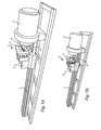
- Figs. 1 a and 1 b schematically illustrate an apparatus according to an embodiment of the invention for manufacturing a catheter tube for insertion into a urethra.
- the apparatus 1 comprises an extruder 2, which will normally include a mixing screw (not shown) leading to an extrusion nozzle 3, such as a die.
- the apparatus can also include a cutting means (not shown) for cutting the extruded tube at a predetermined length.
- Extruders as such are well-known in the art, and no detailed explanation will be provided on the mechanics thereof. An example of an extruder is described in US2008/0193583 , which is hereby incorporated by reference.
- the apparatus 1 further includes a tapered mandrel 4 arranged adjacent the extrusion nozzle 3, and being movable in a direction of the extrusion.
- the tapered mandrel is arranged such that its cross-sectional area increases in the direction of extrusion.
- the tapered mandrel preferably has a conical or frusto-conical shape.
- the mandrel 4 is preferably arranged on a holding structure 6, which is movable along a guide rail 7 in a direction towards and away from the extruder 2.
- the apparatus preferably includes an openable clamping arrangement 5 that can be closed around the tapered mandrel.
- the clamping arrangement includes two clamping elements that are arranged on opposite sides of the tapered mandrel.
- the clamping elements are configured such that, when the clamping elements are closed around the tapered mandrel, the portion of an extruded tube that has been advanced onto the tapered mandrel is pressed against the tapered mandrel such that funnel-shaped connector end is formed.
- a sensor (not shown) may be used to determine a suitable positioning of the extruded tube on the mandrel before closing of the clamping arrangement. As the extruded tube advances onto the tapered madrel the sensor hereby activates the closing of the clamping elements e.g.
- the funnel shaped material on the tappered mandrel surrounded by the clamping elements is moved away frrom the extrusion nozzel and in the same direction as the extrusion direction, at a speed suitable for forming a tube.
- the clamping arrangement comprises two parts which are moevable in relation to each other.
- the clamping arrangement may instead comprise 3, 4, or more parts, depending on the desired shape and design of the funnel shaped end.
- the surface finish of the funnel shaped end might be smooth, or vary in roughness, depending on the design of the outside of the connector.
- the degree of smoothness/roughness may be controlled by arranging a corresponding smoothness/roughness on the inner side of the clamping arrangement.
- the inner side of the clamping arrangement may be used to form embossment, corrugation and the like on the outer surface of the funnel shaped end.
- the inner side of the clamping arrangement may be used to emboss or form a trade name on the funnel shaped end of the tubular object.
- a holding means 8 such as a holding plate, may be arranged beneath the extruded material, to maintain the extruded tube in a relatively straight, and preferably essentially horizontal position.
- the holding plate may e.g. be connected to a rearward part of the clamping arrangement, and be arranged to be withdrawn along with the mandrel as it is moved away from the extruder.
- Fig. 1 a illustrate the apparatus with the clamping arrangement 5 in an opened position
- Fig. 1b illustrate the clamping arrangement 5 in a closed position.
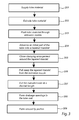
- a tube material is placed in the extruder 2, in step 201.
- the tube material may vary e.g. depending on the desired characteristics of the resulting catheter tube.
- the process has been found to be particularly suitable for extrusion of degradable catheter tubes, i.e. catheter tubes that can be totally dissolved if maintained in water.
- Degradable catheter tubes are preferably primarily made of sugar and/or starch, and preferably comprise at least one of monosaccharide, disaccharide and polysaccharide. Examples of such materials are known from the previous application with application number EP09171080 by the same applicant, which is hereby incorporated by reference.
- the degradable material for extrusion comprises brown syrup (50kg), black syrup (25kg), flour (40kg) water (16+19 kg), liquorices (3 l), carbon black (1 liter), sodium chloride (500 ml), ammonium chloride (7 kg), water (1 liter) and anise oil (60 ml).
- the brown syrup, flour and water (16 kg) are mixed at room temperature until homogenous. NaCl was added and the mixture heated to 90°C until 65-67% water content.
- Black syrup water (19kg), liquorices+ 1l wate, carbon black is added and mixed, and subsequently heated to 98°C until 70-72% water content is reached.
- Salmiak (aq) and anise oil is added and mixed. Thereafter, the mixture rested for 12 h at room temperature, and is then ready for extrusion.
- the extruder 2 is then operated, in step 202, to extrude the tube material, e.g. by initiating the turning of the screw which advances the tube material towards the extrusion nozzle.
- the tube material can be extruded at room temperature in a "cold press" screw extruder without temperature zones. However, it may also be possible to heat the tube material before and/or during extrusion.
- the extruder is operated at room temperature, i.e. 23-25°C.
- the temperature within the extrusion screw will, even when operated at room temperature without additional heating, often be higher. For example, during extrusion with the above-discussed exemplary material at room temperature, wherein a pressure of 4-10 kPa was exerted, a temperature within the extrusion screw of up to ca 50°C was obtained.
- an extruded tube 6 is formed.
- An initial part of the extruded tube is immediately advanced onto the tapered mandrel 4, in step 204, and expanded such that a flared, or funnel-shaped, end 7 is formed.
- Fig. 2a After a predetermined length of the extruded tube has been advanced onto the tapered mandrel such that a desired length of the tube has been expanded, the clamping arrangement 5 is closed around the tapered mandrel, in step 205. This is schematically illustrated in Fig. 2b . As the clamping elements press the flared end of the tube against the tapered mandrel, the flared end is secured at the mandrel. Additionally, the clamping arrangement may be configured to form the flared into a desired shape.
- step 206 the tapered mandrel 4 is pulled away from the extrusion nozzle 3, in the direction of extrusion, and at the same speed as the extruded tube 6 is produced.
- the tapered mandrel remains within and supports the flared end throughout the extrusion process.
- the extruded tube is preferably stretched between the extrusion nozzle and the tapered mandrel. If a relatively soft material is used, the extruded material may be arranged to be expelled in a downward or vertical direction, in order to avoid sagging and the like.
- holding means such as a holding plate or the like, may be arranged to follow the extruded material during extrusion, and to maintain the extruded material in an essentially straight, and preferably essentially horizontal, position.
- the holding means is preferably arranged to be moved together with the mandrel during extrusion.
- step 207 the extruded tube is cut at a desired predetermined length, such that the tube can be removed for subsequent processing.
- the thus formed open ended tube is useable for many applications, and for many types of medical tubular objects, and may e.g. be used as a urinary catheter. However, in case of e.g. urinary catheters, it is often preferred to have a rounded, closed tip portion, and drainage openings formed on the side of the catheter end.
- the tubular object producible in the above-discussed way may also be formed with such a closed distal end. For instance, an insertable end of the tubular object (i.e. the end opposite the flared end) can be formed into a rounded tip portion, in step 208, by e.g. melting and/or by forming at room temperature before drying.
- one or more drainage openings can be formed in the tube wall, in step 209, by e.g. punching and/or blank cutting.
- the punching step might be prior to step 208 i.e prior to the forming and/or closing of the tip end.
- a pin might be inserted into the tube prior to punching, laser cutting etc,
- drainage holes can easily be formed before closing of the tube end by forming a tip.
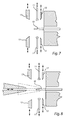
- Fig. 7 schematically illustrate a tip forming device which may be used in conjunction with the apparatus discussed above with reference to Fig.1 , and which may also form an integrated part of this apparatus.
- the nozzle 3 of the extruder 2 is provided with a centrally protruding pin 10.
- the pin 10 preferably protrudes a certain distance, such as 1-3 cm, out from the extruder nozzle 3.
- Punching means 11 are arranged radially separated from the pin 10, and being moveable towards the pin 10 for punching holes in the tube.
- the punching means may use laser or the like for forming the holes, whereby no movement relative to the pin 10 is necessary.
- cutting means 12 radially separated from the pin, such as a mechanical cutting tool, a laser cutting tool or the like, for cutting of the extruded tube.
- a mechanical cutting tool is used, the cutting tool is preferably moveable towards the pin 10.
- the cutting tool is preferably moveable in a circle around the pin 10, to effect complete cutting of the tube.
- a plurality of cutting tools may be provided, which together effect the complete cutting along the circumference of the extruded tube.
- the cutting tools are preferably arranged between the punching means 11 and the extruder 2.
- the cutting may be effected either before, during of after the formation of the holes by the punching means 11.
- tip forming means 13 for forming a rounded, closed tip.
- the tip forming means 13 preferably comprises two or more parts being moveable towards each other, and with inner surfaces being shaped to correspond to the desired shape of the closed tip portion. Thereby, clamping of the parts together around the tube end forms the tip portion to its desired shape.
- the moveable parts may be used without any additional heat. However, preferably, the moveable parts are heated at their forward ends, at the surfaces arranged to be in contact with the tube end, thereby effecting a certain degree of melting of the tube material.
- the tip forming means 13 is preferably arranged at a certain distance from the pin 10 in the axial direction. Hereby, cutting and hole formation may be effected when the tube is still arranged on the pin 10, and thereafter the tube may be pulled, by the mandrel 4 and clamping arrangement 5, away from the pin 10, and to a position where the tip forming means 13 may form the tip portion.
- the mandrel 4 When using the tip forming device shown in Fig. 7 , the mandrel 4 will initially be brought to a position adjacent to, or abutting, the forward end of the centrally protruding pin 10. Since the centrally protruding pin has a relatively limited extension, adequate formation of the extruded tube over the mandrel 4 will still be feasible.
- the mandrel may be brought closer to the extrusion opening.
- this may be effected by providing an opening bore in the mandrel 4, and allowing the mandrel to be at least partly pushed over the centrally protruding pin 10, as is shown schematically in Fig. 8 .
- the mandrel may be arranged as close to the extruder opening as in the initially discussed embodiments, and still allowing a pin to extend out from the extruder nozzle for subsequent use in tip formation.
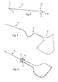
- Fig. 4 schematically illustrates an example of a urinary catheter 10 manufactured according to the above described manufacturing process.
- the illustrated urinary catheter comprises an insertable end 11 provided with draining openings 12 to allow fluid to enter the tube, and a non-insertable end 13 provided with an outlet 14, being in fluid connection with the draining openings 12 via a lumen (not shown) of the tube.
- the non-insertable end 13 of the tube is flared.
- the flared end may serve as a connector 15 for connecting the tube to a receptacle for collection of fluid.
- the flared connector 15 may be connected to the receptacle 16 by means of a tube 17 as illustrated in Fig.5 .
- An alternative is to arrange the catheter inside the receptacle 16, such that the catheter tube may be maneuvered through an opening 17 of the receptacle and pulled out until the flared end 15 forms a mechanical seal connection with the opening 17 at a restriction 18 of the receptacle, as illustrated in Fig. 6 .
- the catheters may be made in various lengths and dimensions.
- the length of the catheter tube for female catheters are in the range 50-200mm, such as with a length in the size of 150 mm, and for male catheters may preferably in a length in the range of 180-450 mm, such as in the size of 400 mm.
- the indicated lengths refer to the length of the catheter tube excluding the flared end.
- the tube may be subject to some degree of shrinkage during drying and cooling. In the exemplary degradable material discussed above, drying at 40°C for 20h typically decreases the diameter with 15-18%, and the length with 8-9%.
- the outer diameter of the tube after drying/cooling is preferably in the range 3-15 mm, and more preferably in the range 5-10 mm, and most preferably in the range 6-7 mm, such as 6.5 mm.
- the inner diameter of the tube after drying/cooling is preferably in the range 1-10 mm, and more preferably in the range 2-6 mm, and most preferably in the range 3-4 mm, such as 3.4 mm.
- the thickness of the tube after drying/cooling is preferably in the range 0.5-4 mm, and more preferably in the range 1-3 mm, and most preferably in the range 1.5-2 mm.
- the flared end preferably has an inner diameter at its largest end in the range 5-15 mm, and more preferably in the range 7-12 mm, and most preferably in the range 9-11 mm, such as 10.4 mm.
- the length of the flared end is preferably in the range 10-100 mm, and more preferably in the range 20-60 mm, and most preferably in the range 25-50 mm, such as 35 mm.
Landscapes
- Health & Medical Sciences (AREA)
- Engineering & Computer Science (AREA)
- Mechanical Engineering (AREA)
- Life Sciences & Earth Sciences (AREA)
- Animal Behavior & Ethology (AREA)
- General Health & Medical Sciences (AREA)
- Biomedical Technology (AREA)
- Heart & Thoracic Surgery (AREA)
- Veterinary Medicine (AREA)
- Public Health (AREA)
- Hematology (AREA)
- Epidemiology (AREA)
- Biophysics (AREA)
- Pulmonology (AREA)
- Anesthesiology (AREA)
- Nursing (AREA)
- Vascular Medicine (AREA)
- Orthopedic Medicine & Surgery (AREA)
- Reproductive Health (AREA)
- Urology & Nephrology (AREA)
- Extrusion Moulding Of Plastics Or The Like (AREA)
- Media Introduction/Drainage Providing Device (AREA)
- Materials For Medical Uses (AREA)
Priority Applications (1)
| Application Number | Priority Date | Filing Date | Title |
|---|---|---|---|
| EP15180547.0A EP2965891A1 (fr) | 2011-05-02 | 2011-05-02 | Procédé pour la fabrication d'un objet tubulaire destiné à être inséré dans une voie de passage corporelle |
Applications Claiming Priority (2)
| Application Number | Priority Date | Filing Date | Title |
|---|---|---|---|
| EP15180547.0A EP2965891A1 (fr) | 2011-05-02 | 2011-05-02 | Procédé pour la fabrication d'un objet tubulaire destiné à être inséré dans une voie de passage corporelle |
| EP11164474.6A EP2520412B1 (fr) | 2011-05-02 | 2011-05-02 | Procédé pour la fabrication d'un objet tubulaire pour l'insertion dans une voie de passage corporelle |
Related Parent Applications (2)
| Application Number | Title | Priority Date | Filing Date |
|---|---|---|---|
| EP11164474.6A Division EP2520412B1 (fr) | 2011-05-02 | 2011-05-02 | Procédé pour la fabrication d'un objet tubulaire pour l'insertion dans une voie de passage corporelle |
| EP11164474.6A Previously-Filed-Application EP2520412B1 (fr) | 2011-05-02 | 2011-05-02 | Procédé pour la fabrication d'un objet tubulaire pour l'insertion dans une voie de passage corporelle |
Publications (1)
| Publication Number | Publication Date |
|---|---|
| EP2965891A1 true EP2965891A1 (fr) | 2016-01-13 |
Family
ID=44317931
Family Applications (2)
| Application Number | Title | Priority Date | Filing Date |
|---|---|---|---|
| EP11164474.6A Not-in-force EP2520412B1 (fr) | 2011-05-02 | 2011-05-02 | Procédé pour la fabrication d'un objet tubulaire pour l'insertion dans une voie de passage corporelle |
| EP15180547.0A Withdrawn EP2965891A1 (fr) | 2011-05-02 | 2011-05-02 | Procédé pour la fabrication d'un objet tubulaire destiné à être inséré dans une voie de passage corporelle |
Family Applications Before (1)
| Application Number | Title | Priority Date | Filing Date |
|---|---|---|---|
| EP11164474.6A Not-in-force EP2520412B1 (fr) | 2011-05-02 | 2011-05-02 | Procédé pour la fabrication d'un objet tubulaire pour l'insertion dans une voie de passage corporelle |
Country Status (10)
| Country | Link |
|---|---|
| US (1) | US9352504B2 (fr) |
| EP (2) | EP2520412B1 (fr) |
| JP (1) | JP6008944B2 (fr) |
| CN (1) | CN103492156B (fr) |
| AU (1) | AU2012251696B2 (fr) |
| BR (1) | BR112013027717B1 (fr) |
| DK (1) | DK2520412T3 (fr) |
| HU (1) | HUE026835T2 (fr) |
| RU (1) | RU2591950C2 (fr) |
| WO (1) | WO2012150251A1 (fr) |
Families Citing this family (14)
| Publication number | Priority date | Publication date | Assignee | Title |
|---|---|---|---|---|
| WO2014077886A1 (fr) | 2012-11-14 | 2014-05-22 | Hollister Incorporated | Cathéter jetable à couche centrale intérieure sélectivement dégradable |
| DK3065793T3 (da) | 2013-11-08 | 2021-05-17 | Hollister Inc | Oleofile smurte katetre |
| AU2014362360B2 (en) | 2013-12-12 | 2020-01-02 | Hollister Incorporated | Flushable catheters |
| ES2802950T3 (es) | 2013-12-12 | 2021-01-22 | Hollister Inc | Catéteres desechables por el inodoro |
| CA2933485C (fr) * | 2013-12-12 | 2023-09-26 | Hollister Incorporated | Catheter se desintegrant dans les toilettes |
| DK3620198T3 (da) | 2013-12-12 | 2021-04-12 | Hollister Inc | Udskyllelige katetre |
| DK3310404T3 (da) | 2015-06-17 | 2024-03-25 | Hollister Inc | Selektivt vanddesintegrerbare materialer og katetre fremstillet af sådanne materialer |
| EP3178514A1 (fr) * | 2015-12-09 | 2017-06-14 | Dentsply IH AB | Cathéter urinaire à connecteur intégré |
| USD842984S1 (en) | 2015-12-09 | 2019-03-12 | Dentsply Ih Ab | Catheter |
| CN106393753A (zh) * | 2016-08-30 | 2017-02-15 | 重庆凯龙科技有限公司 | 用于传感器管路的制备方法 |
| CN109773845B (zh) * | 2019-01-28 | 2021-08-06 | 六安中财管道科技有限公司 | 一种pvc管材、型材移动切割装置 |
| CN109822346B (zh) * | 2019-04-02 | 2024-05-28 | 佛山市顺德区思创自动化机械有限公司 | 留置针扩口组装机 |
| CN110948844A (zh) * | 2019-12-30 | 2020-04-03 | 巢湖市金辉自控设备有限公司 | 一种自动控制的塑胶管扩口裁剪装置 |
| KR102305650B1 (ko) * | 2021-05-21 | 2021-09-29 | (주)명보 | 튜브 어셈블리 제조 장치 및 튜브 어셈블리 제조 방법 |
Citations (3)
| Publication number | Priority date | Publication date | Assignee | Title |
|---|---|---|---|---|
| US4250072A (en) * | 1979-05-18 | 1981-02-10 | Flynn Vincent J | Radiopaque polyurethane resin compositions |
| GB2284764A (en) * | 1993-11-30 | 1995-06-21 | Mmg | Catheter and urine collection device assembly |
| EP0950425A2 (fr) * | 1998-04-15 | 1999-10-20 | Smiths Industries Public Limited Company | Tubes pour la micro-chirurgie et procédés de fabrication |
Family Cites Families (13)
| Publication number | Priority date | Publication date | Assignee | Title |
|---|---|---|---|---|
| FR1077474A (fr) | 1953-01-15 | 1954-11-08 | Procédé et dispositif pour la fabrication de sondes et instruments analogues | |
| US3677684A (en) * | 1969-12-15 | 1972-07-18 | Nat Distillers Chem Corp | Apparatus for enlarging an extremity of a plastic pipe |
| US3708253A (en) * | 1970-09-01 | 1973-01-02 | J Lemelson | Extrusion apparatus |
| US3983203A (en) * | 1973-11-16 | 1976-09-28 | Sherwood Medical Industries Inc. | Method of making a catheter with an integral Luer lock means |
| DE2612993C3 (de) * | 1976-03-26 | 1979-07-12 | Zumbach Electronic Ag, Orpund (Schweiz) | Vorrichtung zur Prüfung der Wandstärke eines Rohres |
| US4234301A (en) * | 1979-03-19 | 1980-11-18 | Hayes Fay A | Gasket feeding apparatus for an inplace gasket belling machine |
| NL9400453A (nl) * | 1994-03-22 | 1995-11-01 | Wavin Bv | Werkwijze en inrichting voor het vervaardigen van biaxiaal georiënteerde buis uit thermoplastisch kunststofmateriaal. |
| DE19751103A1 (de) | 1997-11-18 | 1999-05-27 | Autodesk Inc | Verfahren zum Bemaßen von auf einer Anzeigeeinrichtung dargestellten graphischen Objekten |
| GB9810850D0 (en) * | 1998-05-20 | 1998-07-22 | Smiths Industries Plc | Medico-surgical tubes and methods of manufacture |
| US7604472B2 (en) * | 2003-07-12 | 2009-10-20 | Hayes Jr Frank F | Method and apparatus for forming flared tube ends |
| JP3619239B1 (ja) * | 2003-08-27 | 2005-02-09 | 株式会社プラ技研 | 樹脂製多層チューブの押出成形装置 |
| KR100689238B1 (ko) * | 2005-06-17 | 2007-03-02 | 이근호 | 발룬 카테테르 제조장치 및 그 방법 |
| EP2301595B1 (fr) * | 2009-09-23 | 2014-01-22 | Dentsply IH AB | Cathéter rinçable et procédé de production d'un tel cathéter |
-
2011
- 2011-05-02 DK DK11164474.6T patent/DK2520412T3/en active
- 2011-05-02 EP EP11164474.6A patent/EP2520412B1/fr not_active Not-in-force
- 2011-05-02 EP EP15180547.0A patent/EP2965891A1/fr not_active Withdrawn
- 2011-05-02 HU HUE11164474A patent/HUE026835T2/en unknown
-
2012
- 2012-05-02 WO PCT/EP2012/058008 patent/WO2012150251A1/fr active Application Filing
- 2012-05-02 CN CN201280020306.2A patent/CN103492156B/zh not_active Expired - Fee Related
- 2012-05-02 US US13/461,828 patent/US9352504B2/en active Active
- 2012-05-02 BR BR112013027717-3A patent/BR112013027717B1/pt not_active IP Right Cessation
- 2012-05-02 RU RU2013153265/05A patent/RU2591950C2/ru not_active IP Right Cessation
- 2012-05-02 AU AU2012251696A patent/AU2012251696B2/en not_active Ceased
- 2012-05-02 JP JP2014508778A patent/JP6008944B2/ja not_active Expired - Fee Related
Patent Citations (3)
| Publication number | Priority date | Publication date | Assignee | Title |
|---|---|---|---|---|
| US4250072A (en) * | 1979-05-18 | 1981-02-10 | Flynn Vincent J | Radiopaque polyurethane resin compositions |
| GB2284764A (en) * | 1993-11-30 | 1995-06-21 | Mmg | Catheter and urine collection device assembly |
| EP0950425A2 (fr) * | 1998-04-15 | 1999-10-20 | Smiths Industries Public Limited Company | Tubes pour la micro-chirurgie et procédés de fabrication |
Also Published As
| Publication number | Publication date |
|---|---|
| CN103492156B (zh) | 2016-02-17 |
| EP2520412A1 (fr) | 2012-11-07 |
| AU2012251696A8 (en) | 2015-11-05 |
| JP2014523351A (ja) | 2014-09-11 |
| HUE026835T2 (en) | 2016-07-28 |
| CN103492156A (zh) | 2014-01-01 |
| AU2012251696A1 (en) | 2013-10-17 |
| WO2012150251A1 (fr) | 2012-11-08 |
| BR112013027717B1 (pt) | 2021-03-16 |
| RU2591950C2 (ru) | 2016-07-20 |
| EP2520412B1 (fr) | 2015-08-12 |
| BR112013027717A2 (pt) | 2016-12-27 |
| US20130116662A1 (en) | 2013-05-09 |
| DK2520412T3 (en) | 2015-11-02 |
| RU2013153265A (ru) | 2015-06-10 |
| AU2012251696B2 (en) | 2016-07-21 |
| US9352504B2 (en) | 2016-05-31 |
| JP6008944B2 (ja) | 2016-10-19 |
Similar Documents
| Publication | Publication Date | Title |
|---|---|---|
| AU2012251696B2 (en) | Method for manufacturing of a tubular object for insertion into a body passageway | |
| DE102009030492B4 (de) | Verfahren zur Herstellung eines Kunststoffartikels sowie Blasformwerkzeug | |
| DE102006039656B4 (de) | Vorrichtung und Verfahren zum Herstellen eines Hohlkörpers aus einem rondenförmigen Werkstück | |
| DE69523249T2 (de) | Verfahren zum Blasformen von grossen Behältern durch Streckblasformen | |
| DE69012129T2 (de) | Verfahren zum formen von rohren unter verwendung von pneumatischem unter- und überdruck an der oberfläche des kühldorns. | |
| EP3758910B1 (fr) | Procédé et dispositif pour la fabrication d'un tuyau de conduite à isolation thermique | |
| DE1604689A1 (de) | Verfahren und Vorrichtung zur Formung bzw. Herstellung hohler Gegenstaende | |
| EP3227086A1 (fr) | Dispositif de cintrage d'une pièce de profile à usiner | |
| EP1366884A1 (fr) | Procédé et dispositif pour l'extrusion des tuyaux à épaisseur de paroi variable | |
| CN105121127B (zh) | 用于生产容器的方法和穿孔装置 | |
| WO2008104323A1 (fr) | Procédé et dispositif de fabrication en continu d'un tube d'assemblage en matière plastique avec manchon de raccord | |
| EP3134248B1 (fr) | Dispositif et procédé de formage à chaud d'ébauches de tuyau optimisé en termes de cycle et de complexité | |
| CN211888501U (zh) | 一种用于弯管和直管的管口整形工装 | |
| DE890865C (de) | Verfahren zum Herstellen von Faltenrohren aus thermoplastischen Kunststoffen | |
| DE102009044279B4 (de) | Verfahren zur Herstellung eines Wandanschlussstücks und zugehöriges Wandanschlussstück | |
| DE19627675C2 (de) | Tiefziehsystem zur Herstellung von Hohlkörpern, insbesondere dickbauchigen Behältnissen mit engen Halsbereichen | |
| US11358206B1 (en) | Tubular joint roll forming machine | |
| JP7032949B2 (ja) | 曲げ成形型 | |
| CN114769352B (zh) | 一种不锈钢管成型方法 | |
| DE10259641B4 (de) | Verwendung eines Formwerkzeuges zum Umformen von Halbzeugen aus Kunststoff | |
| AT522497B1 (de) | Verfahren zum Herstellen eines Rohres, sowie Vorrichtung zum Durchführen des Verfahrens | |
| DE102007031876A1 (de) | Extrusionsblasen | |
| CN112742893A (zh) | 一种锥孔挤压式直缝焊管成型装置及其成型方法 | |
| EP1239999B1 (fr) | Procede et appareil permettant de modifier la forme d'un tuyau en plusieurs etapes | |
| CN113618997A (zh) | 一种异型管及其生产工艺 |
Legal Events
| Date | Code | Title | Description |
|---|---|---|---|
| PUAI | Public reference made under article 153(3) epc to a published international application that has entered the european phase |
Free format text: ORIGINAL CODE: 0009012 |
|
| AC | Divisional application: reference to earlier application |
Ref document number: 2520412 Country of ref document: EP Kind code of ref document: P |
|
| AK | Designated contracting states |
Kind code of ref document: A1 Designated state(s): AL AT BE BG CH CY CZ DE DK EE ES FI FR GB GR HR HU IE IS IT LI LT LU LV MC MK MT NL NO PL PT RO RS SE SI SK SM TR |
|
| STAA | Information on the status of an ep patent application or granted ep patent |
Free format text: STATUS: THE APPLICATION IS DEEMED TO BE WITHDRAWN |
|
| 18D | Application deemed to be withdrawn |
Effective date: 20160714 |