EP0949385B1 - Assemblage d'éléments d'évacuation d'un lavabo - Google Patents
Assemblage d'éléments d'évacuation d'un lavabo Download PDFInfo
- Publication number
- EP0949385B1 EP0949385B1 EP99302751A EP99302751A EP0949385B1 EP 0949385 B1 EP0949385 B1 EP 0949385B1 EP 99302751 A EP99302751 A EP 99302751A EP 99302751 A EP99302751 A EP 99302751A EP 0949385 B1 EP0949385 B1 EP 0949385B1
- Authority
- EP
- European Patent Office
- Prior art keywords
- washbasin
- drain
- drain assembly
- rod
- lift rod
- Prior art date
- Legal status (The legal status is an assumption and is not a legal conclusion. Google has not performed a legal analysis and makes no representation as to the accuracy of the status listed.)
- Expired - Lifetime
Links
- 239000002699 waste material Substances 0.000 claims description 5
- 230000008878 coupling Effects 0.000 claims description 4
- 238000010168 coupling process Methods 0.000 claims description 4
- 238000005859 coupling reaction Methods 0.000 claims description 4
- 230000000284 resting effect Effects 0.000 claims description 2
- 239000007788 liquid Substances 0.000 claims 1
- 238000007789 sealing Methods 0.000 claims 1
- 229910001220 stainless steel Inorganic materials 0.000 description 7
- 239000010935 stainless steel Substances 0.000 description 7
- 239000010797 grey water Substances 0.000 description 4
- XLYOFNOQVPJJNP-UHFFFAOYSA-N water Substances O XLYOFNOQVPJJNP-UHFFFAOYSA-N 0.000 description 4
- 238000009434 installation Methods 0.000 description 3
- 239000007769 metal material Substances 0.000 description 3
- 239000002861 polymer material Substances 0.000 description 3
- 239000007787 solid Substances 0.000 description 3
- 229920001059 synthetic polymer Polymers 0.000 description 3
- 239000000356 contaminant Substances 0.000 description 2
- 239000003365 glass fiber Substances 0.000 description 2
- 239000002184 metal Substances 0.000 description 2
- 230000002093 peripheral effect Effects 0.000 description 2
- 238000004140 cleaning Methods 0.000 description 1
- 230000006835 compression Effects 0.000 description 1
- 238000007906 compression Methods 0.000 description 1
- 238000011109 contamination Methods 0.000 description 1
- 230000000694 effects Effects 0.000 description 1
- 230000002349 favourable effect Effects 0.000 description 1
- 239000000835 fiber Substances 0.000 description 1
- 239000010806 kitchen waste Substances 0.000 description 1
- 238000012423 maintenance Methods 0.000 description 1
- 230000014759 maintenance of location Effects 0.000 description 1
- 239000000463 material Substances 0.000 description 1
- 210000002445 nipple Anatomy 0.000 description 1
- 239000002245 particle Substances 0.000 description 1
- 230000000717 retained effect Effects 0.000 description 1
Images


Classifications
-
- E—FIXED CONSTRUCTIONS
- E03—WATER SUPPLY; SEWERAGE
- E03C—DOMESTIC PLUMBING INSTALLATIONS FOR FRESH WATER OR WASTE WATER; SINKS
- E03C1/00—Domestic plumbing installations for fresh water or waste water; Sinks
- E03C1/12—Plumbing installations for waste water; Basins or fountains connected thereto; Sinks
- E03C1/22—Outlet devices mounted in basins, baths, or sinks
- E03C1/23—Outlet devices mounted in basins, baths, or sinks with mechanical closure mechanisms
- E03C1/2302—Outlet devices mounted in basins, baths, or sinks with mechanical closure mechanisms the actuation force being transmitted to the plug via rigid elements
-
- E—FIXED CONSTRUCTIONS
- E03—WATER SUPPLY; SEWERAGE
- E03C—DOMESTIC PLUMBING INSTALLATIONS FOR FRESH WATER OR WASTE WATER; SINKS
- E03C1/00—Domestic plumbing installations for fresh water or waste water; Sinks
- E03C1/12—Plumbing installations for waste water; Basins or fountains connected thereto; Sinks
- E03C1/22—Outlet devices mounted in basins, baths, or sinks
- E03C1/23—Outlet devices mounted in basins, baths, or sinks with mechanical closure mechanisms
-
- E—FIXED CONSTRUCTIONS
- E03—WATER SUPPLY; SEWERAGE
- E03C—DOMESTIC PLUMBING INSTALLATIONS FOR FRESH WATER OR WASTE WATER; SINKS
- E03C1/00—Domestic plumbing installations for fresh water or waste water; Sinks
- E03C1/12—Plumbing installations for waste water; Basins or fountains connected thereto; Sinks
- E03C1/26—Object-catching inserts or similar devices for waste pipes or outlets
- E03C1/264—Separate sieves or similar object-catching inserts
-
- E—FIXED CONSTRUCTIONS
- E03—WATER SUPPLY; SEWERAGE
- E03C—DOMESTIC PLUMBING INSTALLATIONS FOR FRESH WATER OR WASTE WATER; SINKS
- E03C1/00—Domestic plumbing installations for fresh water or waste water; Sinks
- E03C1/12—Plumbing installations for waste water; Basins or fountains connected thereto; Sinks
- E03C1/22—Outlet devices mounted in basins, baths, or sinks
- E03C1/23—Outlet devices mounted in basins, baths, or sinks with mechanical closure mechanisms
- E03C2001/2315—Outlet devices mounted in basins, baths, or sinks with mechanical closure mechanisms the actuation force created by a turning movement of a handle
Definitions
- This invention relates to a washbasin drain assembly.
- Design of subsystems of a commercial passenger aircraft is a continuing pursuit of a favorable balance between functionality and weight.
- a basin made of stainless steel is heavier than a basin of comparable size and made of a material having a higher strength-to-weight ratio than stainless steel, such as a glass fiber reinforced synthetic polymer material.
- the thickness of the basin In order to provide a basin of sufficient strength made from non-metallic material, the thickness of the basin must generally be greater than the thickness of a basin made of stainless steel.
- the drain body that is connected to the outlet opening of the lavatory washbasin in a commercial passenger aircraft is connected to a waste line which supplies the gray water from the basin either to a pressure responsive valve which feeds the gray water to a drain mast for discharge from the aircraft or to a vacuum interface valve for supplying the water to a vacuum sewer through which the water is delivered to a collecting tank aboard the aircraft.
- a waste line which supplies the gray water from the basin either to a pressure responsive valve which feeds the gray water to a drain mast for discharge from the aircraft or to a vacuum interface valve for supplying the water to a vacuum sewer through which the water is delivered to a collecting tank aboard the aircraft.
- a vacuum interface valve for supplying the water to a vacuum sewer through which the water is delivered to a collecting tank aboard the aircraft.
- there may be other devices downstream of the drain body there may be other devices downstream of the drain body.
- a solid contaminant in the gray water may interfere with operation of the interface valve or other downstream device and may lead to a flooding condition.
- strainer in the outlet of a washbasin to prevent solid objects from entering the drain line.
- the purpose of the strainer may be either to protect against loss, e.g. of small items of jewelry, or to protect against blockage of the drain line, e.g. by kitchen waste.
- the strainer openings are fairly large, typically having a minimum linear dimension of at least 5 mm.
- a downstream device such as a vacuum interface valve
- an improved washbasin drain assembly for fitting in a outlet opening of a washbasin and connecting to a waste line, according to claim 1.
- FIG. 1 illustrates a relatively thin washbasin 4 made of a metallic material such as stainless steel and having an inner rim surrounding an outlet opening 8.
- a drain body 12 which has an external flange 14 and is internally threaded at 16, is positioned below the outlet opening of the washbasin.
- a seat 20 has a flange 22 above the outlet opening of the basin and an extension sleeve extending through the outlet opening and in threaded engagement with the drain body 12.
- the annular margin surrounding the outlet opening of the basin is clamped between the flanges 14 and 22, and a gasket is provided to prevent leakage of water between the flange 14 and the underside of the basin.
- the seat 20 defines a drain passage connecting the interior space of the washbasin to the drain body.
- the seat 20 has an internal flange or shoulder 44 at the lower end of its extension sleeve.
- a filter subassembly 48 includes a mesh cup 52 with a circular opening at its bottom end and an annular rim 56 at its top end, and a tube 60 attached to the cup 52 and extending upward from the circular opening at the bottom of the cup.
- the filter subassembly 48 is located in the drain body with the annular rim 56 resting on the shoulder 44 so that the tube 60 is coaxial with the drain body 12.
- the aperture size of the mesh cup 52 depends on the nature and structure of the downstream device to be protected and the nature of the contaminants against which the downstream device is to be protected. Research has shown that the type of debris that is deposited in the lavatory washbasin of a commercial passenger aircraft depends on the route served by the aircraft. Therefore the actual mesh size may depend on the route. If the service of a particular aircraft is changed, the mesh size of the filter to be installed in that aircraft can also be changed. The size may be in the range from 40 ⁇ m to 5 mm, preferably 100 ⁇ m to 2 mm.
- the tube 60 is constructed with a solid wall in order to afford sufficient rigidity to allow it to be gripped by service personnel without collapsing the tube.
- the drain body has a lateral stub 80 just above the connection nipple 24.
- the purpose of the lateral stub 80 will be described below.
- the stopper assembly 40' includes a circular plug 88 having an annular flange formed with a peripheral groove containing an O-ring.
- a guide sleeve 92 formed with openings 96 is attached to the plug 88 and extends downward from the annular flange.
- a cylindrical socket 100 formed with inverted J-shaped slots 102 projects downward from the plug and is removably coupled to a lift rod 104 which extends axially within the drain body, passing through the tube 60, and has a stem 108 fitted in the guideway 34 and restrained against lateral movement by the guide webs 32.
- FIG. 2 shows several views of the stopper subassembly 40' in order to illustrate the manner in which the plug 88 is attached to the lift rod 104.
- the sleeve 92 is not shown in FIG. 2, in order to avoid concealing the socket 100.
- the lift rod 104 is formed with lower and upper transverse bores through which respective pins 106, 108 extend.
- the upper pin 108 functions as a bayonet pin for coupling the plug 88 to the lift rod 104 by engagement in the J-shaped slots.
- a spring 112 is captive on the lift rod between the two pins. When the plug 88 is engaged with the lift rod 104, the spring 112 is held in compression between the lower pin 106 and the lower end of the socket 100.
- the circular plug 88 is disengaged from the lift rod 104 by pressing down on the plug and rotating it clockwise through 90° in order to align the upper pin 108 with the slots 102.
- the plug can then be removed from the seat, exposing the filter subassembly.
- the lift rod 104 is formed with two transverse openings 116.
- a pivot rod 120 extending through a ball journalled in the lateral stub 80 and held captive by a cap nut 84' having an inner end which threads the upper opening 116.
- Angular movement of the pivot rod 120 about a horizontal axis is transmitted through the lift rod to the plug 88, which can be raised toward an open position, in which it is clear of the seat 20 and water can flow from the basin into the drain body, and lowered toward a closed position in which it seals the drain passage.
- the guide sleeve 92 serves to guide movement of the plug 88 relative to the seat 20 and the openings 96 prevent large particles from entering the drain body 12.
- the coupling of the lift rod 104 to the pivot rod 120 and the coupling of the plug 88 to the lift rod 104 provide positive retention of the plug 88 and lift rod 104.
- the filter is designed to maximize the filter area within the space available in the drain body 10.
- the available space is limited by the lift rod and the connection to the pivot rod.
- the cup is about 5.5 cm long and about 2.3 cm in diameter.
- the basin 4 is mounted in a deck 124. Spaced somewhat from the rim of the basin 4 is a circular opening in the deck and a draw bar guide 132 is fitted in this opening and is held in position by a nut.
- the draw bar guide 132 defines a circular bore through which a draw bar 136, provided at its upper end with an actuator knob, is fitted slidably.
- a detent mechanism cooperating with peripheral grooves in the draw bar establishes two principal operating positions (open and closed) for the draw bar.
- a linkage rod 140 has upper and lower vertical segments and inner and outer (with respect to the drain body 12) horizontal segments.
- the draw bar 136 is provided with a clamp 144 having a first jaw which grips the lower end of the draw bar 136 and a second jaw which grips the upper vertical segment of the linkage rod 140.
- the upper clamp 144 holds the upper vertical segment of the linkage rod substantially parallel to the draw bar.
- the upper clamp can be attached to the draw bar at any angular position about the axis of the draw bar and it can also be attached to the upper vertical segment of the linkage rod at any angular position about a vertical axis. Further, the vertical position at which the upper clamp grips the upper segment of the linkage rod is adjustable.
- the inner horizontal segment of the linkage rod is attached to the pivot rod 120 by a lower clamp 148, which can be attached to the pivot rod and the inner horizontal segment of the linkage rod at any horizontal. position.
- the lower clamp includes a swivel allowing the angular position of the inner horizontal segment relative to the pivot rod to vary about a vertical axis. Play in the connection between the linkage rod and the pivot rod allows limited angular relative movement of the inner horizontal segment and the pivot rod about a horizontal axis perpendicular to the lift rod.
- This arrangement of the linkage rod and the upper and lower clamps provides wide flexibility in location of the draw bar guide 132 relative to the basin 4. Because the lower vertical segment connects the inner and outer horizontal segments, the linkage rod does not encroach substantially on the space immediately below the draw bar, leaving this space available for other equipment.
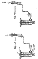
- FIGS. 3A and 3B illustrate the drain assembly of FIG. 1 in the open and closed conditions respectively.
- the drain body is attached to the basin by a mounting nut in threaded engagement with the drain body.
- the annular margin of the basin is clamped between the flanges of the seat 20 and the drain body 12. This is advantageous in an aircraft application because it avoids the need for the mounting nut, which adds weight and is a potential source of failure due to the possibility of loosening through vibration.
- the annular margin of the basin 4 is clamped between the flanges of the seat 20 and the drain body 12, the vertical position of the lateral stub 80 relative to the seat 20 depends on the thickness of the basin.
- the thickness of the basin 4' is significantly greater than the thickness of the basin 4 shown in FIGS. 3A and 4B and so the flange 22 of the seat 20 is higher relative to the drain body 12.
- the vertical distance between the flange 22 of the seat 20 and the lateral stub 80 significantly greater in the case of FIGS. 4A and 4B than in the case of FIGS. 3A and 3B. Accordingly, the range of movement through which the stopper subassembly 40' must move in order to lift the plug is shifted upward relative to the arrangement shown in FIGS. 3A and 3B.
- the inner end of the pivot rod is fitted in the lower opening 116, as shown in FIGS. 4A and 4B. It will therefore be seen that use of two openings 116 in the lift rod allows the same drain assembly to be used not only with a thin basin made of metal but also with a thicker basin, such as one made of a glass fiber reinforced synthetic polymer material.
Landscapes
- Engineering & Computer Science (AREA)
- Environmental & Geological Engineering (AREA)
- Health & Medical Sciences (AREA)
- Life Sciences & Earth Sciences (AREA)
- Hydrology & Water Resources (AREA)
- Public Health (AREA)
- Water Supply & Treatment (AREA)
- Mechanical Engineering (AREA)
- Sink And Installation For Waste Water (AREA)
Claims (7)
- Ensemble d'évacuation pour un lavabo destiné à être installé dans une ouverture de sortie (8) d'un lavabo (4) et à être connecté à une canalisation de décharge, comprenant un corps d'évacuation (12) qui définit un passage d'évacuation reliant l'espace intérieur du lavabo (4) à la canalisation de décharge et un ensemble de bouchon (40', 88) en engagement coopérant avec le corps d'évacuation (12) pour sceller de manière sélective le passage d'évacuation, lequel ensemble d'évacuation comprend en outre un sous-ensemble de filtre amovible (48, 52, 56, 60) arrangé dans le corps d'évacuation (12) en aval de l'ensemble de bouchon (40', 88) par rapport à la direction d'écoulement du liquide depuis le lavabo (4) vers la canalisation de décharge, caractérisé en ce que le sous-ensemble de filtre (48, 52, 56, 60) comporte une coupelle en treillis (52) ayant une ouverture circulaire au niveau de son extrémité inférieure et un tube (60) s'étendant vers le haut depuis cette ouverture, en ce que l'ensemble de bouchon (40', 88) est connecté à une bielle de relevage (104) s'étendant à travers le tube (60) et à un bouchon (88) attaché à la bielle de relevage (104) pour engager le siège (20), et en ce que la bielle de relevage (104) est arrangée de manière à lever et abaisser sélectivement le bouchon (88).
- Ensemble d'évacuation pour un lavabo selon la revendication 1, caractérisé en ce que le sous-ensemble de filtre (4, 8, 52, 56, 60) comporte une coupelle en treillis (52) ayant une dimension de maille dans la plage de 40 µm à 5 mm.
- Ensemble d'évacuation pour un lavabo selon la revendication 1, caractérisé en ce que l'ensemble d'évacuation comprend un siège (20) ayant un bride (22) s'étendant par-dessus une bordure interne annulaire du lavabo (4) entourant l'ouverture de sortie (8) de celui-ci et un manchon s'étendant vers le bas depuis la bride (22) dans le corps d'évacuation (12), et en ce que le sous-ensemble de filtre (48, 52, 56, 60) est supporté par le siège (20).
- Ensemble d'évacuation pour un lavabo selon la revendication 3, caractérisé en ce que le siège (20) comporte un épaulement intérieur (44) et en ce que le sous-ensemble de filtre (48, 52, 56, 60) comporte un rebord (56) reposant sur l'épaulement (44).
- Ensemble d'évacuation pour un lavabo selon la revendication 1, caractérisé en ce que la bielle de relevage (104) comprend au moins deux trous transversaux (116), en ce que le corps d'évacuation (12) est pourvu d'un tronçon latéral (80), et en ce qu'une bielle pivotante (120) est prévue pour s'engager sélectivement avec les trous (116) de la bielle de relevage (104) à travers le tronçon latéral (80).
- Ensemble d'évacuation pour un lavabo selon la revendication 5, caractérisé en ce que l'ensemble d'évacuation pour lavabo est arrangé dans une plate-forme (124), en ce qu'un guide de barre d'attelage (132) est monté dans la plate-forme (124), et en ce qu'un accouplement de bielle (13, 144, 140, 148) est arrangé à coulissement en relation avec le guide de barre d'attelage (132) en vue de l'engagement avec la bielle pivotante (120).
- Ensemble d'évacuation pour un lavabo selon la revendication 1, caractérisé en ce que le bouchon (88) est attaché de manière détachable à la bielle de relevage (104).
Applications Claiming Priority (2)
| Application Number | Priority Date | Filing Date | Title |
|---|---|---|---|
| US57993 | 1998-04-09 | ||
| US09/057,993 US6023795A (en) | 1998-04-09 | 1998-04-09 | Washbasin drain assembly |
Publications (3)
| Publication Number | Publication Date |
|---|---|
| EP0949385A2 EP0949385A2 (fr) | 1999-10-13 |
| EP0949385A3 EP0949385A3 (fr) | 2000-08-09 |
| EP0949385B1 true EP0949385B1 (fr) | 2004-10-13 |
Family
ID=22013992
Family Applications (1)
| Application Number | Title | Priority Date | Filing Date |
|---|---|---|---|
| EP99302751A Expired - Lifetime EP0949385B1 (fr) | 1998-04-09 | 1999-04-08 | Assemblage d'éléments d'évacuation d'un lavabo |
Country Status (3)
| Country | Link |
|---|---|
| US (1) | US6023795A (fr) |
| EP (1) | EP0949385B1 (fr) |
| DE (1) | DE69921003T2 (fr) |
Families Citing this family (22)
| Publication number | Priority date | Publication date | Assignee | Title |
|---|---|---|---|---|
| US6154898A (en) * | 1999-05-19 | 2000-12-05 | Wcm Industries, Inc. | Wastewater drain control for fluid compartments |
| JP2002004376A (ja) * | 2000-06-19 | 2002-01-09 | Jamco Corp | 排水弁 |
| PL352340A1 (en) * | 2002-02-20 | 2003-08-25 | Roman Arseniuk | Drain-off outlet with a strainer |
| AU2003221626B2 (en) * | 2002-05-02 | 2006-08-17 | Pipesafe Pty Limited | Pipe filter and closure assembly |
| AUPS207102A0 (en) * | 2002-05-02 | 2002-06-06 | Stephenson, Mark Andrew | Pipe filter and sealing apparatus |
| NL1021226C2 (nl) * | 2002-08-07 | 2004-02-10 | Marinus Van Eijk | Geïntegreerd zeefsysteem. |
| DE102004048992B4 (de) * | 2004-10-04 | 2015-02-05 | Dieter Küchenmeister | Abflussvorrichtung für Sanitärbecken und Verwendung der Abflussvorrichtung in einem Spülbecken |
| US7886372B2 (en) * | 2005-02-11 | 2011-02-15 | As Ip Holdco, L.L.C. | Drain assembly for rapid installation in sanitary vessels |
| US8869319B2 (en) * | 2005-09-13 | 2014-10-28 | Hayward Industries, Inc. | Circular suction outlet assembly and cover |
| DE102006004225B4 (de) * | 2006-01-30 | 2012-07-12 | Airbus Operations Gmbh | Duschablauf in Flugzeugen |
| US7856680B2 (en) * | 2006-01-30 | 2010-12-28 | Airbus Deutschland Gmbh | Shower drainage outlet in aircraft |
| US8065758B1 (en) | 2006-05-17 | 2011-11-29 | Edgar Gabriel Mendez | Lavatory vessel liquid dispenser |
| US8407829B2 (en) | 2007-11-30 | 2013-04-02 | Masco Corporation Of Indiana | Coupling for a faucet lift rod |
| US8407828B2 (en) | 2007-11-30 | 2013-04-02 | Masco Corporation Of Indiana | Faucet mounting system including a lift rod |
| CN101215848B (zh) * | 2008-01-10 | 2010-06-09 | 宁波搏盛阀门管件有限公司 | 一种洗槽下水的开关装置 |
| US20100235983A1 (en) * | 2009-03-19 | 2010-09-23 | Jones Chad H | Pop-Up Stopper Assembly |
| US9151027B2 (en) * | 2010-11-03 | 2015-10-06 | Art Plastics Pty Ltd | Bathroom fittings |
| US20120192799A1 (en) * | 2011-01-28 | 2012-08-02 | Bazemore Sr Tommy | Drainable Aquarium with Redundant Leak Prevention |
| CN103835348B (zh) * | 2013-04-17 | 2016-04-06 | 路达(厦门)工业有限公司 | 排水塞连动装置 |
| US9624656B2 (en) | 2013-07-30 | 2017-04-18 | Jarrod Colacino | Drain cover assembly |
| US10358804B1 (en) | 2016-12-01 | 2019-07-23 | American Airlines, Inc. | Lavatory sink drain assembly |
| US11555552B2 (en) * | 2020-10-12 | 2023-01-17 | B/E Aerospace, Inc. | Retainer guidance for rinsing valves |
Family Cites Families (20)
| Publication number | Priority date | Publication date | Assignee | Title |
|---|---|---|---|---|
| US989410A (en) * | 1910-05-09 | 1911-04-11 | Harry A Peters | Strainer for sink-outlets. |
| US1161766A (en) * | 1915-04-03 | 1915-11-23 | Ernest Ferran | Sink-strainer. |
| US1612588A (en) * | 1926-06-11 | 1926-12-28 | Lacoste Patrick | Sink strainer |
| US2032525A (en) * | 1933-01-16 | 1936-03-03 | Frank G Brotz | Lavatory waste and fitting |
| US1980280A (en) * | 1933-06-24 | 1934-11-13 | John D Martin | Liner for grape shipping boxes |
| US1976549A (en) * | 1934-04-26 | 1934-10-09 | Foose Edward | Drain fixture for sinks |
| US2348093A (en) * | 1943-06-19 | 1944-05-02 | Abram N Pasman | Waste outlet fitting |
| US2475048A (en) * | 1945-12-15 | 1949-07-05 | Smith Corp A O | Stopper |
| US2859453A (en) * | 1956-04-02 | 1958-11-11 | Bloch Leon | Drain control device for bath tubs |
| FR1255751A (fr) * | 1960-04-29 | 1961-03-10 | Dispositif de commande de vidange pour lavabos et installations analogues | |
| US3169254A (en) * | 1962-10-16 | 1965-02-16 | Sterling Faucet Company | Simplified lavatory drain pipe assembly |
| US3727763A (en) * | 1971-08-24 | 1973-04-17 | P Arenskov | Strainer-stopper assembly |
| US4045351A (en) * | 1975-12-31 | 1977-08-30 | Peterson Carl M | Sink strainer device |
| DE2842490A1 (de) * | 1978-09-29 | 1980-04-10 | Thorwarth & Grebe Ohg | Ablaufverschluss fuer waschbecken, spuelbecken o.dgl. |
| DE2900812C2 (de) * | 1979-01-11 | 1980-11-06 | Hans Grohe Gmbh & Co Kg, 7622 Schiltach | Schutzkappe für Ablaufventile von Waschbecken, Wannen u.dgl |
| GB2233894A (en) * | 1989-07-18 | 1991-01-23 | Brec Builders Ltd | Obturating device |
| EP0531316A4 (en) * | 1990-05-04 | 1993-05-26 | Jattke, Udo | Hydrostatic drain plug |
| DE9007043U1 (de) * | 1990-06-25 | 1990-08-30 | Rauer, Dietmar, 4100 Duisburg | Abwasserfilterventil |
| DE4414357A1 (de) * | 1994-04-25 | 1995-10-26 | Norbert Scherer | Waschbeckenauslaufgarnitur mit Haarsieb |
| DE29610774U1 (de) * | 1996-06-19 | 1996-08-29 | Cheng, Tsan-Hsiung, Tainan City | Abflußleitungsanordnung |
-
1998
- 1998-04-09 US US09/057,993 patent/US6023795A/en not_active Expired - Lifetime
-
1999
- 1999-04-08 EP EP99302751A patent/EP0949385B1/fr not_active Expired - Lifetime
- 1999-04-08 DE DE69921003T patent/DE69921003T2/de not_active Expired - Lifetime
Also Published As
| Publication number | Publication date |
|---|---|
| US6023795A (en) | 2000-02-15 |
| EP0949385A3 (fr) | 2000-08-09 |
| DE69921003D1 (de) | 2004-11-18 |
| EP0949385A2 (fr) | 1999-10-13 |
| DE69921003T2 (de) | 2006-02-02 |
Similar Documents
| Publication | Publication Date | Title |
|---|---|---|
| EP0949385B1 (fr) | Assemblage d'éléments d'évacuation d'un lavabo | |
| KR900004457B1 (ko) | 전환 밸브 | |
| US4856121A (en) | Air gap faucet | |
| US3314085A (en) | Concealed pop-up valve for waste drains | |
| EA008425B1 (ru) | Пробка для сливного отверстия | |
| US10889967B2 (en) | Vacuum breaker with back flow preventer | |
| EP0572468A1 (fr) | Raccords de soupape de vidange | |
| US2250291A (en) | Vacuum breaker for water systems | |
| GB2425818A (en) | Set of components for the modular construction of an outlet assembly | |
| JPH04297631A (ja) | ハンドシャワーユニットの設置構造 | |
| CA1116976A (fr) | Clapet antiretour | |
| US5881398A (en) | Washbasin valve with integrated water trap | |
| US5038814A (en) | Back flow preventer and integral vacuum breaker | |
| US3512545A (en) | Airgap | |
| GB2541476A (en) | Plumbing connector having non-return valve | |
| NO164259B (no) | Ventil til bruk i en sugeledning for drenering av vaeske. | |
| JP4324888B2 (ja) | 吸排気弁 | |
| US6584625B2 (en) | Drain flow control device for commercial drainage system | |
| CN216278726U (zh) | 一种便于安装的油管防溢阀 | |
| EP2297497B1 (fr) | Agencement de vanne d'eaux usées | |
| US6499501B1 (en) | Conduit system for proximate flow of clean and waste water | |
| US7465399B1 (en) | Filtered and unfiltered water ducting in sink fitting | |
| WO2021058237A1 (fr) | Siphon d'appareil sanitaire réglable doté d'une soupape d'arrêt | |
| CN215137413U (zh) | 一种除污过滤器 | |
| CN216007157U (zh) | 水槽下水器 |
Legal Events
| Date | Code | Title | Description |
|---|---|---|---|
| PUAI | Public reference made under article 153(3) epc to a published international application that has entered the european phase |
Free format text: ORIGINAL CODE: 0009012 |
|
| AK | Designated contracting states |
Kind code of ref document: A2 Designated state(s): DE FR |
|
| AX | Request for extension of the european patent |
Free format text: AL;LT;LV;MK;RO;SI |
|
| RAP1 | Party data changed (applicant data changed or rights of an application transferred) |
Owner name: EVAC INTERNATIONAL OY |
|
| PUAL | Search report despatched |
Free format text: ORIGINAL CODE: 0009013 |
|
| AK | Designated contracting states |
Kind code of ref document: A3 Designated state(s): AT BE CH CY DE DK ES FI FR GB GR IE IT LI LU MC NL PT SE |
|
| AX | Request for extension of the european patent |
Free format text: AL;LT;LV;MK;RO;SI |
|
| 17P | Request for examination filed |
Effective date: 20001204 |
|
| AKX | Designation fees paid |
Free format text: DE FR |
|
| GRAP | Despatch of communication of intention to grant a patent |
Free format text: ORIGINAL CODE: EPIDOSNIGR1 |
|
| RIN1 | Information on inventor provided before grant (corrected) |
Inventor name: HEMMER, NATHAN A., Inventor name: MCGOWAN,ARTHUR J. JR., Inventor name: POETTER, JOCHEN, |
|
| GRAS | Grant fee paid |
Free format text: ORIGINAL CODE: EPIDOSNIGR3 |
|
| GRAA | (expected) grant |
Free format text: ORIGINAL CODE: 0009210 |
|
| RIN1 | Information on inventor provided before grant (corrected) |
Inventor name: HEMMER, NATHAN A., Inventor name: MCGOWAN,ARTHUR J. JR., Inventor name: POETTER, JOCHEN, |
|
| AK | Designated contracting states |
Kind code of ref document: B1 Designated state(s): DE FR |
|
| PG25 | Lapsed in a contracting state [announced via postgrant information from national office to epo] |
Ref country code: FR Free format text: LAPSE BECAUSE OF FAILURE TO SUBMIT A TRANSLATION OF THE DESCRIPTION OR TO PAY THE FEE WITHIN THE PRESCRIBED TIME-LIMIT Effective date: 20041013 |
|
| REF | Corresponds to: |
Ref document number: 69921003 Country of ref document: DE Date of ref document: 20041118 Kind code of ref document: P |
|
| PLBE | No opposition filed within time limit |
Free format text: ORIGINAL CODE: 0009261 |
|
| STAA | Information on the status of an ep patent application or granted ep patent |
Free format text: STATUS: NO OPPOSITION FILED WITHIN TIME LIMIT |
|
| 26N | No opposition filed |
Effective date: 20050714 |
|
| EN | Fr: translation not filed | ||
| REG | Reference to a national code |
Ref country code: DE Ref legal event code: R082 Ref document number: 69921003 Country of ref document: DE Representative=s name: K & H BONAPAT PATENTANWAELTE KOCH - VON BEHREN, DE Ref country code: DE Ref legal event code: R082 Ref document number: 69921003 Country of ref document: DE Representative=s name: K & H BONAPAT, DE Ref country code: DE Ref legal event code: R082 Ref document number: 69921003 Country of ref document: DE Representative=s name: GRAF GLUECK HABERSACK KRITZENBERGER, DE |
|
| PGFP | Annual fee paid to national office [announced via postgrant information from national office to epo] |
Ref country code: DE Payment date: 20120920 Year of fee payment: 14 |
|
| PG25 | Lapsed in a contracting state [announced via postgrant information from national office to epo] |
Ref country code: DE Free format text: LAPSE BECAUSE OF NON-PAYMENT OF DUE FEES Effective date: 20131101 |
|
| REG | Reference to a national code |
Ref country code: DE Ref legal event code: R119 Ref document number: 69921003 Country of ref document: DE Effective date: 20131101 |