EP0947592B1 - Copper alloy and method of manufacturing same - Google Patents
Copper alloy and method of manufacturing same Download PDFInfo
- Publication number
- EP0947592B1 EP0947592B1 EP97939214A EP97939214A EP0947592B1 EP 0947592 B1 EP0947592 B1 EP 0947592B1 EP 97939214 A EP97939214 A EP 97939214A EP 97939214 A EP97939214 A EP 97939214A EP 0947592 B1 EP0947592 B1 EP 0947592B1
- Authority
- EP
- European Patent Office
- Prior art keywords
- brass
- phase
- sec
- hot
- temperature
- Prior art date
- Legal status (The legal status is an assumption and is not a legal conclusion. Google has not performed a legal analysis and makes no representation as to the accuracy of the status listed.)
- Expired - Lifetime
Links
Images


Classifications
-
- C—CHEMISTRY; METALLURGY
- C22—METALLURGY; FERROUS OR NON-FERROUS ALLOYS; TREATMENT OF ALLOYS OR NON-FERROUS METALS
- C22F—CHANGING THE PHYSICAL STRUCTURE OF NON-FERROUS METALS AND NON-FERROUS ALLOYS
- C22F1/00—Changing the physical structure of non-ferrous metals or alloys by heat treatment or by hot or cold working
- C22F1/08—Changing the physical structure of non-ferrous metals or alloys by heat treatment or by hot or cold working of copper or alloys based thereon
-
- C—CHEMISTRY; METALLURGY
- C22—METALLURGY; FERROUS OR NON-FERROUS ALLOYS; TREATMENT OF ALLOYS OR NON-FERROUS METALS
- C22C—ALLOYS
- C22C9/00—Alloys based on copper
- C22C9/04—Alloys based on copper with zinc as the next major constituent
Definitions
- This invention relates to a method of manufacturing metal products.
- This invention is related to Cu-Zn-based copper alloy, that is brass, and a method of manufacturing brass.
- Metals such as aluminum and stainless steel have been known to present 1000% or higher elongation. This excellent elongation is obtained because the strain is released by grain boundary sliding of crystal grains.
- the grain boundary sliding works most effectively when an external force of such a strain rate as 0.01/sec. This is why aluminum and stainless steel show high ductility when they undergo such low-rate external force.
- an external force of a high strain rate exceeding 0.1/sec is given to crystal grains, the grain boundary sliding does not work effectively and crystal grains undergo substantial dislocation, thereby developing cracks in the metal.
- metals may be recrystallized by thermal energy or a strain energy due to deformation in working (dynamic recrystallization). Dynamic recrystallization for improving ductility is practically employed in manufacturing metals such as brass.
- Brass is applied to a wide variety of applications, and properties required to brass differ depending on the application. For example, brass for forging requires high ductility against an external high-rate force mentioned above. Brass applied to parts kept contact with water (valves, faucet fittings, etc.), requires high corrosion resistance and high erosion resistance to water. Furthermore, high strength and machinability are also required in various applications.
- Copper alloy known to have excellent corrosion resistance to water is Cu-Zn-Sn-based copper alloy (JIS C4641) or naval brass bar, and Cu-Zn-based copper alloy (JIS C6782) or high tensile brass bar.
- Corrosion resistance of brass mainly means resistance to dezincing. Because of the difference of ionization tendency of Cu and Zn, Zn is liable to dissolve in water faster than Cu and, as a result, the brass reduces its Zn content and loses strength with the lapse of time. Such phenomenon is called dezincing, which becomes the important problem when the brass is applied to water-contact parts.
- the conventional arts have produced brass which is substantially in a single phase of ⁇ phase without depositing the ⁇ phase, which is very inferior in corrosion resistance.
- the above-mentioned conventional brass which is substantially of the single ⁇ phase is inferior in mechanical strength and machinability.
- the conventional brass having crystal structure of ⁇ + ⁇ type has good mechanical strength and machinability, it is inferior in corrosion resistance since the ⁇ phase is extremely inferior in corrosion resistance. In other words, in the conventional arts, it is difficult to manage to enhance corrosion resistance and mechanical strength as well as machinability simultaneously.
- JP-A-3110042 discloses a method for producing brass with improved hot rolling workability.
- the brass has a Zn content of 25-45wt%. From a melt temperature of ⁇ 1050°C the brass is cooled at a rate of ⁇ 100°C/s
- a metal so constructed that, when it is given an external force and deformed, the strain in the crystal structure will disperses.
- the strain energy caused by the deformation can work as an energy source for recrystallization.
- the strain in the crystal structure disperses without concentrating locally, thereby producing a large strain energy which enables recrystallization and prevents crystal grains from dislocating.
- a metal that presents high ductility by an external high-rate force is provided.
- Also disclosed herein is a method of manufacturing metal products - which contains hot- working process of metal on conditions that if strain energy of metal crystals deformed by an external force in hot working is denoted by SE, and heat energy given to the metal crystals by heating in hot working is denoted by TE; SE+TE > Minimum energy necessary for recrystallization of deformed metal crystal TE ⁇ Energy necessary for a crystal grain to coarsen under the condition of no external-force.
- a metal in hot working is not heated up to such high temperature as the crystal grains coarsen so as to reduce the ductility.
- the method offers a way to satisfy the conditions needed for the strain energy in metal caused by deformation due to an external force to become large enough so that effective recrystallization takes place even at a relatively low temperature (energy due to deformation is considered potential energy caused by dislocation).
- such conditions can be adjusted so that the metal crystal structure to be subjected to hot working develops strain dispersedly when subjected to an external force (dispersion of strain is microscopically considered to be dispersion of dislocation ).
- crystal grains do not coarsen when heated, and dynamic recrystallization takes place effectively in a metal when an external force in working is given, thus realizing high ductility to an external high-rate force.
- crystal structure that develops strain when given an external force is a mixture of relatively soft and hard crystals of sufficiently fine grain size.
- soft crystals when given an external force, soft crystals deform (supposedly due to the grain boundary sliding between soft and hard crystals), and the deformed soft crystals migrate and disperse.
- the crystal structure mentioned above can be realized by an alloy which contains two kinds of metal elements and deposit a soft and hard crystal phase, typically brass, which is an alloy of Cu and Zn.
- Embodied examples of an alloy of this invention are ⁇ + ⁇ -, ⁇ + ⁇ + ⁇ - and ⁇ + ⁇ - type brass of fine crystal grains of 15 ⁇ m or smaller in diameter.
- a third element contributing to accelerate recrystallization rate may be solid-dissolved in soft crystals of the alloy made of two kinds of metals as mentioned above.
- the typical third element for example, is Sn in brass the atomic radius of which resembles closely to the above-mentioned two kinds of metal elements so that substitutional solid solution in soft crystals may take place.
- the present method proposes to provide brass possessing ⁇ + ⁇ crystal structure within the temperature range for recrystallization, and also satisfying the following conditions within the recrystallization temperature range :
- a desirable example of such a brass has the following high hot ductility within the recrystallization temperature range:
- the conventional brass cannot realize such high elongation percentage as mentioned above.
- the conventional superplastic materials e.g. aluminum and stainless steel
- the conventional superplastic materials are not provided with good ductility against high-rate strain as in (1) and (2) above.
- the " ⁇ + ⁇ type" brass possesses ⁇ + ⁇ crystal-structure in room temperature, and also in room temperature satisfies the following conditions:
- the " ⁇ + ⁇ + ⁇ type" brass possesses ⁇ + ⁇ + ⁇ crystal-structure at room temperature, and also at room temperature satisfies the following conditions:
- this type of brass may preferably be manufactured to satisfy the following conditions at room temperature:
- the " ⁇ + normal ⁇ type" brass possesses ⁇ + ⁇ crystal-structure at room temperature, and also at room temperature satisfies the following conditions:
- the " ⁇ + reinforced ⁇ type" brass possesses ⁇ + ⁇ crystal-structure at room temperature, and also at room temperature satisfies the following conditions:
- Machining resistance index based on, as the reference, the free-cutting brass bar conforming to JIS (Japanese Industrial Standard) C 3604 is 80 or higher.
- SPZ zinc aluminum
- aluminum are, when placed in water, inferior in corrosion resistance, and particularly aluminum develops pitting.
- these metals are tough, they are also inferior in machinability.
- the present invention proposes to manufacture brass with a step of manufacturing brass castings by performing casting under the following conditions:
- the production method of this invention further contains the step of making brass extrusions by performing, after performing casting as mentioned above, hot extrusion of the above-mentioned brass castings within the temperature range of 480°C-650°C, preferably 480°C-600°C.
- the cooling rate after the hot extrusion is, preferably 0.4K/sec or higher, until the temperature is lowered to 400°C or below.
- a method of manufacturing the brass according to this invention contains a step of producing brass extrusions by hot-extruding brass the apparent Zn content of which is 37%-46% by wt. under the following conditions:
- This production method may further contain the step of making brass forgings by reheating and hot-forging the above-mentioned brass extrusions within the temperature range of 480°C-750°C.
- the strain rate in hot-forging is preferably 1/sec or higher. Such rapid hot-forging will not increase the crystal grain size.
- the cooling rate after hot forging is preferably 0.4K/sec or higher, until the temperature is lower to 400°C or below. Due to this rapid cooling, crystal grains do not increase in diameter even after the cooling, thus remaining as fine crystal grains of 15 ⁇ m or smaller size.
- cooling conditions of 0.4 - 5K/sec may be selected until cooling rate after hot extrusion or hot forging is lowered to 400°C or below.
- a heat-treatment step may be added so that the brass forging can be heated and kept at 400-550°C for 30 sec or longer and then cooled at a cooling rate of 0.4-5K/sec until its temperature is lowered to 400°C or below.
- a cooling condition of 0.4 - 10K/sec may be selected until the temperature after hot extrusion or hot forging is lowered to 400°C or below.
- a heat-treatment step following the hot forging process may be added so that the brass forging can be heated and kept at 450-550°C for 30 sec or longer and then cooled at a cooling rate of 0.4-10K/sec until its temperature is lowered to 400°C or below.
- a cooling condition of 5 - 1000K/sec may be selected until the cooling rate after hot extrusion or hot forging is lowered to 400°C or below.
- a heat-treatment step following the hot forging process may be added so that the brass forging can be heated and kept at 475-550°C for 30 sec or longer and then cooled at a cooling rate of 5-1000K/sec or higher until its temperature is lowered to 400°C or below.
- a further method of producing brass contains the step of: heating and then cooling the brass of the apparent Zn content of 37-46% by wt., and controlling at least any one of heating temperature, heat retaining time and cooling rate so that the crystal structure of the cooled brass can be selected out of the ⁇ + ⁇ , ⁇ + ⁇ + ⁇ , and ⁇ + ⁇ types.
- the cooling rate may be controlled to the lowest rate for obtaining the ⁇ + ⁇ type, and to a higher rate for obtaining the ⁇ + ⁇ + ⁇ type. and to the highest rate for obtaining the ⁇ + ⁇ type.
- the brass produced according to this invention can exhibit good machinability and mechanical strength.
- the machining resistance index based, as a reference, on the free cutting brass bar conforming to JIS (Japanese Industrial Standard) C 3604 can be 80 or higher, and o.2% yield strength or the yield stress can be 300 N/mm 2 or mores
- no copper alloy has been provided with such good machinability and strength.
- bronze has cutting resistance index of 80 or more, its 2% yield strength is only about 80 N/mm 2 and its tensile strength is only about 220 N/mm 2 . It is generally difficult to improve the strength of bronze because the copper content of bronze is 79% or more.
- One of the ways of improving the strength of bronze is to increase the Sn content of bronze.
- the brass produced by the method of this invention are provided with the following stress corrosion cracking resistance: When a cylindrical specimen of such brass is exposed to an ammoniacal atmosphere over 14% ammonia water for 24 hours under a load, the maximum stress under which the specimen does not crack is 180 N/mm 2 or more.
- improvements in strength and corrosion resistance are essential (though other factors are also required).
- the SCC resistance is improved in this invention by taking advantage of excellent corrosion resistance of copper.
- bronze is less durable to stress and causes plastic deformation by stress of about 100 N/mm 2 .
- the brass produced by the method of this invention can have the following good machinability and corrosion resistance: Its machining resistance index based, as the reference, on the free-cutting brass bar is 80 or higher, and when a dezinking corrosion test is conducted in accordance with a technical standard T-303 of JBMA, the maximum dezinking penetration depth is 100 ⁇ m or less if the direction of the maximum dezinking penetration depth is parallel with the working direction, and 70 ⁇ m or less if the direction of the maximum dezinking penetration depth is rectangular to the working direction.
- free-cutting brass bars are inferior in corrosion resistance, and when a dezinking test is conducted as mentioned above, the maximum dezinking penetration depth reaches approximately 200 ⁇ m.
- One of the ways of improving machinability of brass is to reduce the average crystal grain size to 15 ⁇ m or smaller, preferably 10 ⁇ m or smaller.
- the parts softer than the ⁇ phase are composed of such metals as Pb and Bi, that is, metals other than the metal constituting the ⁇ phase.
- the parts harder than the ⁇ phase are composed of the ⁇ or ⁇ phases, intermetallic compounds such as FeSi and FeP, or oxides of Cu and Mg.
- brass may be produced by the following method.
- the ⁇ phase For the ⁇ + ⁇ type of crystal structure, it is effective to make the ⁇ phase contain Sn preferably in a quantity 8% by wt. or more.
- the ⁇ phase For the ⁇ + ⁇ type of crystal structure, it is effective to make the ⁇ phase contain third elements (e.g. Sn, Si, Al, Sb, Ge or Ga) for the purpose of improving corrosion resistance.
- the Sn concentration in the phase is preferably 1.5% by wt. or higher.
- it is also effective to produce crystal structure composed of the ⁇ phase, ⁇ phase and parts which surround crystal grains of the ⁇ phase and offers higher corrosion resistance than that of the ⁇ phase.
- the parts which offer higher corrosion resistance than the ⁇ phase does is, for example, the ⁇ phase that contains Sn of 8% by wt. or more.
- the ⁇ phase that contains Sn of 8% by wt. or more.
- the brass having machinability and corrosion resistance improved by following the teachings of this specification is applicable to a variety of applications, especially to water piping parts. Because the average crystal grain size of the brass made available by this invention is small, the brass is rather inferior in cold ductility. However, for applications to water piping parts, which do not require such high cold ductility as martensite and shape memory alloys possess, such brass can fully satisfy the product quality required for the parts.
- This invention makes available a wide variety of products using brass.
- copper alloys of Cu-Zn system cover a wide range, including water contact parts such as faucets and water supply pipes, electric household appliances, mechanical parts, architectural materials, gas fittings, and optical instrument parts.
- water contact parts such as faucets and water supply pipes, electric household appliances, mechanical parts, architectural materials, gas fittings, and optical instrument parts.
- copper alloys it is required to excel not only in general properties, such as mechanical strength, cold rollability, hardness, machinability, and polishability, but also in different properties required as water contact parts, such as corrosion resistance, erosion resistance, and resistance to stress corrosion cracking.
- One principle of this invention attaches importance for improving the above-mentioned properties to properties of crystal phases of Cu-Zn alloys.
- the crystal phase present three phases, ⁇ , ⁇ and ⁇ , have been known so far.
- the ⁇ phase excels in corrosion resistance and mechanical strength, but it has not been tried to utilize such properties positively because of its high brittleness.
- the ⁇ phase has low corrosion resistance and has been considered to be unsuitable to water contact parts.
- the ⁇ phase excels in corrosion resistance and cold ductility but is inferior in strength and machinability.
- properties of respective phases have been rendered a fixed idea, and no positive attempt to alter properties of crystal phases has so far been made.
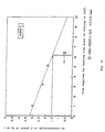
- FIG. 1 shows properties of three phases which appear in Cu-Zn alloys and those of pure Cu, Zn and Sn.
- pure Cu is inferior in yield strength and machinability (easiness to be machined) although it excels in corrosion resistance, ductility at room temperature and cold forgeability (easiness to be cold-forged).
- a Cu-Zn alloy to which Zn is added is conventionally used for wide range of applications.
- the Cu-Zn alloys come to differ in crystal structure by quantity of Zn to be added.
- the apparent Zn content of a Cu-Zn alloy is 37% or less by weight, the crystal structure becomes a single ⁇ phase, and when the apparent Zn content is larger than 37%, the ⁇ phase appears in the crystal structure of the alloy (as ⁇ + ⁇ or ⁇ type).
- the ⁇ phase appears (as ⁇ + ⁇ + ⁇ , ⁇ + ⁇ , or ⁇ + ⁇ type or single ⁇ phase). Even when the true Zn content is low, the apparent Zn content increases and the ⁇ phase appears if Sn (having Zn equivalent of 2) is added and the alloy is subjected to a special heat treatment.
- apparent Zn content means "[(B+t ⁇ Q)/(A+B+t ⁇ Q)] ⁇ 100", where A is the Cu content (% by wt.), B is the Zn content (% by wt.), t is Zn equivalent (% by wt.) of an added third element, for example, Sn, and Q is the content of the third element (% by wt.).
- the single ⁇ phase excels in corrosion resistance and cold forgeability, it is inferior in yield strength and machinability. Addition of Sn can improve the corrosion resistance and yield strength of the Cu-Zn alloys, but the 2% by wt or more addition of Sn tends to make the alloys brittle.
- the ⁇ phase has properties approximately contrary to the ⁇ phase in that the ⁇ phase excels in yield strength, hot forgeability (easiness to be hot-forged) and machinability although it is inferior in corrosion resistance and cold forgeability.
- One knowledge the inventors obtained is that addition of Sn to crystal grains of the ⁇ phase improves corrosion resistance and yield strength; particularly the corrosion resistance is improved to a degree nearly comparable to the alloy of the single ⁇ phase.
- the ⁇ phase appears when Sn is added in a specific quantity or more to the Cu alloy.
- the ⁇ phase excels in corrosion resistance and yield strength although it is brittle.
- the "corrosion resistance" of copper alloys means mainly resistance to dezinking corrosion.
- the dezinking corrosion is defined as such a phenomenon that because of difference between Cu and Zn in the ionization tendency, Zn is eluted into water earlier than other elements, thus decreasing the strength of the alloy with the lapse of time. This is a problem confronted when the Cu-Zn alloy is used.
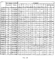
- FIGs. 2A-2C show compositions and properties of 19 examples of brass extrusions made according to thi invention in comparison with brass (as references) according to conventional technology.
- examples 1-19 are described below.
- the alloys have crystal structure of ⁇ + ⁇ type, whose crystal grains are microcrystallized (to 15 ⁇ m or smaller), and the ⁇ phase having improved properties is effectively utilized.
- the alloys have crystal structure of ⁇ + ⁇ + ⁇ type, whose crystal grains are microcrystallized, and the ⁇ and ⁇ phases which have improved properties are effectively utilized.
- Examples 13-15 have crystal structure of ⁇ + ⁇ type, whose crystal grains are microcrystallized.
- Examples 16-19 have crystal structure of ⁇ + ⁇ type, whose crystal grains are microcrystallized, and their ⁇ phase has properties improved by addition of Sn. Furthermore, in these examples 1-19, the ratio of respective crystal phases has been appropriately adjusted. Details of crystal structure of these examples are described later.
- the alloys of examples 1-19 were produced by casting brass samples having compositions shown in FIG. 2A under the production conditions according to the principles of this invention, hot-extruding these samples, and then hot-forging the extrusions (the actual production flow is shown in FIG. 3).
- the heat treatment conditions shown in FIGs. 2A-2C are casting temperatures and cooling methods.
- the cooling rate of air cooling is 0.8K/sec, and that of water cooling is 100K/sec.
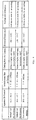
- FIGs 2A-2C are listed as properties "0.2% yield strength (N/mm 2 )” (tensile stress causing permanent elongation of 2%), “cold ductility (%)” (ductility in a cold working zone), “hardness (HV)", “hot ductility” (ductility in a hot working temperature zone, i.e. in a recrystallization temperature zone), “cutting resistance index”, “corrosion resistance”, “erosion resistance” and “stress corrosion cracking resistance” (SCC resistance).
- the "corrosion resistance” was evaluated in accordance with judgment criteria shown by a technical standard (JBMA T-303) of Japan Brass Makers Association on the result of dezinking tests conducted in accordance with the JBMA T-303. That is, in the case where the direction of dezinking penetration depth is parallel with the working direction, the maximum dezinking depth of 100 ⁇ m or less was evaluated as good (o), and in the case where the direction of dezinking penetration depth is rectangular to the working direction, the maximum dezinking depth of 70 ⁇ m or less was evaluated as good (o). The results that do not satisfy these criteria was decided as poor ( ⁇ ).
- the "erosion resistance" was evaluated as good (o) when the tightening torque required for preventing the sample from leakage after the lapse of 1500 hours under the test conditions described later was less than 0.8 N ⁇ m, and as poor ( ⁇ ) when the tightening torque was 8% or more.
- the stress corrosion cracking resistance was evaluated as good (o) when the sample did not crack after the lapse of 24 hours under the test conditions described later, and as poor ( ⁇ ) when the sample cracked on the same condition as above.
- samples 1-5 were evaluated as good (o) or excellent ( ⁇ ) as to the yield strength, cold ductility, corrosion resistance, erosion resistance and stress corrosion cracking resistance.
- Examples 1 and 2 were evaluated as poor ( ⁇ ) as to machinability, and such evaluation is supposed to be for the reason that both the samples did not satisfy the optimum conditions where the ⁇ phase is to be 3% or more and the ⁇ phase is to be 5% or more.
- Hot ductility of example 1 was also evaluated as poor ( ⁇ ); this evaluation is supposed to be for the reason that in the hot working the ⁇ phase did not reach 30% because the apparent Zn content was less than 38%.
- examples 13-15 were evaluated as good (o) or excellent ( ⁇ ).
- the evaluation results of corrosion resistance and erosion resistance of examples 13-15 as poor ( ⁇ ) is supposed to be for the reason that these samples do not contain the ⁇ phase, and that the Sn concentration in their ⁇ phase does not reach 1.5% by wt.
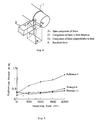
- FIG. 1 shows one example of a production process using hot forging for brass products.
- a mixture of electrolytic copper, electrolytic zinc and scraps is melted and cast into an intermediate form.
- the formed castings are rapidly cooled and extruded in the form of bar- or wire rod-shaped billets.
- the bar- or wire rod-shaped billets are subjected to cold drawing, annealing and pickling. Then the billets are cut to a predetermined length.
- step 4 the billets are heated for securing properties suitable for forging in the next step 5.
- step 5 the hot billets are set into forging dies, and forged. Then, as preparation for progressing to step 6, the forgings are cooled. After the cooling, the forgings are pickled and shot-blasted to remove the thin oxide coating formed on the surfaces, and deburred.
- step 7 through working of cutting, grinding and plating, final products are obtained.
- FIGs. 4 and 5 compare two examples of the production methods of this invention (methods 1 and 2 of this invention) in accordance with the production process shown in FIG. 3 in comparison with a conventional production method.
- the "apparent Zn content” is involved in the mixing ratio of the materials melted at step 1 shown in FIG. 1, the "solidification rate at casting” and “cooling rate after casting” are involved in casting conditions at step 1, and the “extrusion temperature” and “cooling after extrusion” are involved in conditions of hot extrusion at step 2.
- the "grain size” means that of the billets after hot extrusion at step 2 (and also the crystal grain size of final products in this invention); the " ⁇ -phase ratio", “forging temperature” and “strain and strain rate” are involved in forging condition at step 5; and the “yield strength” and " ⁇ -, ⁇ -, and ⁇ -phase ratios after forging” mean those of the products finished at step 7.
- the apparent Zn content of methods 1 and 2 of this invention is high (typically the quantity of Sn addition is large), the solidification rate at hot casting and the cooling rate after casting are high, the temperature in hot extrusion (at step 2) is low, and the cooling rate after the extrusion is high (practically the extrusions are cooled at 0.4K/sec or a higher rate).
- the sectional area reduction by extrusion is 90% or more, preferably 95% or more, which is not shown in FIG. 4.
- billets prepared by methods 1 and 2 of this invention can be forged at low forging temperature and at a high strain and strain rate (at step 5) as compared with the billets prepared by the conventional method.
- Such advantages are suppose to be for the reason that as shown in FIG. 5, the billets by methods 1 and 2 of this invention have smaller crystal grain size than that of billets obtained by the conventional method, and contain the ⁇ phase, which excels in hot ductility even at relatively low forging temperature, at an appropriate ratio. It is advantageous to allow forging at lower temperatures because deterioration of the forging equipment can be reduced.
- the yield strength of the products forged by methods 1 and 2 of this invention is substantially larger than that of products of the conventional forging.
- FIG. 6 shows hot ductility of two kinds of billets, one produced by a method of this invention and the other produced by the conventional method (actually example 10 and reference 4, which are shown in FIGs, 2A-2C) in the forging temperature zone.
- the abscissa shows the strain rate (sec -1 ), and the ordinate shows strain ⁇ L (%).
- Example 10 is obviously superior in hot ductility to reference 4.
- FIG. 7 shows results of cutting tests conducted on reference 3, examples 8, 10 and 11, free cutting brass bars (JIS C 3604), and brass of single ⁇ phase.
- a main component force Fv was measured while cutting the circumferential surface of a round-bar sample 1 with a lath at two different speeds of 100 and 400 m/min.
- the cutting resistance index of each sample is expressed as percentage of a main component force of a free cutting brass bar which has been said to have the best machinability, to the main component force of each sample.
- the cutting resistance indexes of example 8, 10 and 11 reach near 90% of that of the free cutting brass bar having the best machinability with the results better than that of reference 3 and the single ⁇ -phase brass bar.
- FIG. 9 shows results of erosion resistance tests on examples 8 and 11 and reference 4 shown in FIGS. 2A-2C
- FIG. 10 portrays the method of erosion resistance tests.
- the erosion resistance tests were conducted using a cylindrical sample 5 having an orifice inside. After water was passed through the orifice at a flow velocity of 40 m/sec for a predetermined period of time, tightening torque required for tightening a disk seat 9 to seal the orifice 7 under hydraulic pressure of 4.9 ⁇ 10 5 Pa (5 kg/cm 2 ) was determined.
- FIG. 9 it can be seen that examples 8 and 11 have higher erosion resistance than that of reference 4.
- SCC strain corrosion cracking
- a cylindrical sample placed in a glass desiccator 11 as shown in FIG. 11 was exposed to an atmosphere of NH 3 vapor for 24 hours, and then checked the sample on cracking.
- Fig. 12 shows test results (relationship between main stress and cracking) of examples 8, 11 and 15, and reference 4. From FIG. 9, it is realized that examples 8, 11 and 15 have higher SCC resistance than that of reference 4.
- examples 1-19 of this invention shown in FIGs, 2A-2C have good properties.
- examples 16-19 have properties improved by microcrystallizing the crystal structure of ⁇ + ⁇ type (to 15 ⁇ m or finer) and also by adding Sn to the ⁇ phase, and this type of brass according to this invention is hereinafter referred to as " ⁇ + reinforced ⁇ type".
- Examples 1-5 have properties improved by microcrystallizing the crystal grain size in the crystal structure of ⁇ + ⁇ type and also by utilizing the ⁇ phase.
- This type of brass is hereinafter referred to as " ⁇ + ⁇ type.”
- Examples 6-12 have properties improved by microcrystallizing the crystal grain size in the crystal structure of ⁇ + ⁇ + ⁇ type and also by utilizing the ⁇ phase.
- This type of brass is hereinafter referred to as " ⁇ + ⁇ + ⁇ type.”
- Examples 13-15 have properties improved by microcrystallizing the crystal grain size in the crystal structure of ⁇ + ⁇ type.
- This type of brass is hereinafter referred to as " ⁇ + normal ⁇ type.”
- This type of crystal structure has an intercrystalline ⁇ phase that contains 1.5% by wt. or more of Sn between crystal grains of the ⁇ phase.
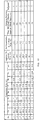
- FIG. 13 the compositions, apparent Zn content, Sn concentrations in the ⁇ phase and results of corrosion resistance tests (to dezinking corrosion) of examples 1-7 are listed.
- the Sn concentrations in the ⁇ phase were adjusted by heat and cooling treatment and quantitatively analyzed by EPMA analysis.
- the corrosion resistance was judged by the method described already in connection with FIGs. 2A-2C.
- FIG. 14 is a graph showing results of experiments on the relationship between cooling time for cooling from heat treatment temperatures down to 400°C and the Sn concentration in the ⁇ phase. From FIG. 14, it is realized that when the cooling rate in the period from the start of cooling down to 400°C is 0.4K/sec or higher (in the zone on the left side of point (1) in FIG. 14), the Sn concentration in the ⁇ phase becomes 1.5% by wt. or more. Further the experiments proved that as the upper limit of the cooling rate, the rates up to at least 1000K/sec are permissible. Furthermore, not only in the case where the heat treatment temperature is 550°C, but also even in such other cases as the heat treatment temperature of 510°C, the same experimental results as above were obtained.
- FIG. 15 shows results of experiments conducted to study the effect of the heat treatment temperature (temperature of sample specimens in heat treatment) and heat treatment time (time in which the heat treatment temperature is retained) on the Sn concentration in the ⁇ phase and the areal occupation ratio of the ⁇ phase.
- FIG. 15 reveals that the Sn concentration in the ⁇ phase increases with rise of the heat treatment temperature, or with extension of the heat treatment time.
- the areal occupation ratio of the ⁇ phase decreases with rise of the heat treatment temperature, or extension of the heat treatment time.
- the heat treatment temperature shown in FIG. 15 is in the range of 475-550°C and the heat treatment time is 30 sec. or longer, it is possible to increase the Sn concentration in the ⁇ phase. Extending the heat treatment time increases the Sn content in the ⁇ phase, thus improving the corrosion resistance.
- the heat treatment time is preferably 3 hr or shorter.
- FIG. 16A is a microscopic photograph showing crystal structure of a brass sample, No. 7, represented in FIG. 18.
- FIG. 16B is a schematic drawing of crystal structure prepared on the basis of FIG. 16A.
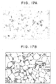
- FIG. 17A is a microscopic photograph showing crystal structure of a brass sample, No. 4, represented in FIG. 18.
- FIG. 17B is a schematic drawing of crystal structure prepared on the basis of FIG. 17A.
- the ⁇ phase black spots in the figure
- the ⁇ phase has disappeared.
- the crystal structure shown in FIG. 17A contains the ⁇ and ⁇ phases, and the ⁇ phase deposits on grain boundaries of the ⁇ phase (larger white areas in the figure)) and the ⁇ phase (smaller white areas in the figure) so as to surround the ⁇ phase.
- the average grain size is smaller than the average grain sizes of the ⁇ and ⁇ phases, for example, 8 ⁇ m or smaller, preferably 5 ⁇ m or smaller.
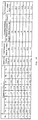
- FIG. 18 tabulates brass samples, Nos. 1-7, of 7 examples related to the " ⁇ + ⁇ type” and " ⁇ + ⁇ + ⁇ type” of this invention (which differ from the examples shown in FIGs. 2A-2C).
- the items shown in FIG. 18 are the composition, apparent Zn content, areal occupation ratio of the " ⁇ phase”, test results of corrosion resistance (dezinking corrosion resistance), and Sn concentration in the ⁇ phase.
- the corrosion resistance test was conducted by a method described in connection with FIGs, 2A-2C.
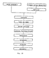
- FIG. 19 shows an example of the methods for producing brass products according to this invention.
- the production method shown in FIG. 19 forms brass of a Cu-Zn-Sn system having such compositions as samples, Nos. 3-7, shown in FIG. 18, by hot forging or hot extrusion.
- the formed intermediate products are subjected to heat treatment at temperature of 400°C or higher and 550°C or lower for 30 sec or longer retaining time, and then cooled down to 400°C at a cooling rate of 0.4K/sec or more and 10K/sec or below.
- the crystal structure of the formed intermediate products turns to the " ⁇ + ⁇ type" or " ⁇ + ⁇ + ⁇ type".
- the formed intermediate products are machined, ground or plated.
- FIG. 21 shows results of experiments conducted to study the relationship of the areal occupation ratio to heat treatment conditions.
- a Cu-Zn-Sn alloy which has composition of sample NO. 3 shown in FIG. 18 was heat-treated under conditions of different treatment temperatures (temperatures of the sample) and different lengths of temperature retaining time, and after each heat treatment, the areal occupation ratio (%) of the ⁇ phase was determined.
- the cooling rate down to 400°C after the heat treatment was 0.4-5K/sec when the treatment temperature is 425°C or below, or 5-10K/sec when the treatment temperature is 450°C or below.
- the areal occupation ratio of the ⁇ phase becomes 3% or more when the heat treatment temperature is 550-400°C, the retaining time is 30 sec or longer, and the cooling rate is in the range of 5-10K/sec.
- the heat treatment temperature exceeds 550°C, the areal occupation ratio of the ⁇ phase does not increase but reveals the reverse tendency to decrease even if the retaining time is extended. Therefore, to increase the areal occupation ratio of the ⁇ phase to 3% or higher, the treatment temperature has to be 550°C or below.
- crystal structure of the " ⁇ + ⁇ type" is formed
- crystal structure of the " ⁇ + ⁇ + ⁇ type" is formed in the heat treatment temperature range of 450-550°C.
- the average crystal grain size is 15 ⁇ m or less, preferably 10 ⁇ m or less.
- Such fine crystal grains allow hot forging at rather lower temperature than in the cases of conventional production method, and has advantages of rather high hot ductility (in the forging temperature zone) and yield point strength (yield strength).
- Different conditions of the production process contribute to microcrystallization of the crystal grains.
- the following conditions can be selected for microcrystallizing the crystal grains.
- the quantity of Zn to be mixed is adjusted so that the ratio of the ⁇ phase to the ⁇ phase in the recrystallization temperature zone can be 30-80%. It is useful for causing dynamic recrystallization during the subsequent hot extrusion or hot forging to maintain the ratio of the ⁇ phase in the above limits (the crystal grain size becomes smaller when the dynamic crystallization occurs).
- the metal mixture is rapidly cooled at a cooling rate of 5K/sec until the temperature of the mixture is lowered to 400°C or below, thus forming intermediate products.
- Such rapid cooling can microcrystallize the crystal grains.
- Another method effective for microcrystallizing the crystal grains in the forging step is to add such elements as B, Fe, Ni, P, Co, Nb, Ii and Zr to the alloy.
- Appropriate ratios of their addition are 0.05-0.5 for B, 0.01-2.0 for Fe, 0.05-0.2 for Ni, 0.04-0.2 for P, 0.01-2.0 for Co, 0.01-0.2 for Nb, 0.01-1.0 for Ti, 0.005-0.5 for Zr.
- P and Fe manifests a synergistic effect.
- the above-mentioned formed intermediate product is heated to the temperature range of 480-650°C (preferably 480-600°C), and formed to bars or wire rods by hot extrusion in this temperature range (step 2).
- the sectional area reduction ratio is set to 90% or more (preferably 95%) to cause effective dynamic recrystallization, thus preventing oversizing of the crystal grains.
- the products are rapidly cooled at a 0.4K/sec or larger rate until the temperature of the products is lowered to 400°C or below to prevent oversizing of the crystal grains. Furthermore lowering the temperature for heating the intermediate products and shortening the heating time are also effective for preventing oversizing of crystal grains.
- the bars or wire rods are cold-extruded, annealed, pickled and cut to a predetermined size to obtain billets for forging (step 3).
- the billets obtained in such a way is heated to secure properties appropriate for the subsequent hot forging.
- the heating temperature is kept in the range of 480-750°C, and the heating time is shortened.
- the heated billets are set into forging dies, and hot-forged in the temperature range of 480-750°C (step 5).
- shortening the interval of time from start of heating to forging operation is effective for suppressing the oversizing of the crystal grains and keeping crystal grains fine.
- the products are cooled to prepare for next pickling or shot blasting.
- it is advantageous to keep the cooling rate at 0.4K/sec or more.
- the microcrystallization of crystal grains is affected by the cooling rate after the casting, conditions of the extrusion, etc. First, a contribution of the cooling rate to the microcrystallization of crystal grains is described in detail with reference to FIGs. 22-25.
- FIG. 22A is a microscopic photograph showing crystal structure of in-process brass produced at a cooling rate of 10K/sec after the casting.
- FIG. 22B is a schematic drawing prepared on the basis of FIG. 22A.
- FIG. 23A is a microscopic photograph in which a part of FIG. 22B is enlarged.
- FIG. 23B is a schematic drawing prepared on the basis of FIG. 22A.
- FIG. 24A is a microscopic photograph showing crystal structure of in-process brass produced at a cooling rate of 1.3K/sec after the casting.
- FIG. 24B is a schematic drawing prepared on the basis of FIG. 24A.
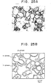
- FIG. 25A is a microscopic photograph in which a part of FIG. 24A is enlarged.
- FIG. 25B is a schematic drawing prepared on the basis of FIG. 25A.
- the higher rate of microcrystallization can be realized by increasing the cooling rate after the casting.
- the cooling rate for example, at the cooling rate of 19K/sec the crystal structure that has an average crystal grain size of 15 ⁇ m or less and in the whole area of which the ⁇ and ⁇ phases are mixed is obtained.
- the cooling rate at the cooling rate of 1.3K/sec the crystal structure that has average crystal grain size of 15 ⁇ m or more is obtained, and besides deposition of the ⁇ phase on the boundary between both the ⁇ phase and the ⁇ phase is observed.
- the average crystal grain size was determined according to the relevant JIS.. Furthermore, subsequent experiments proved that in order to reduce the average crystal grain size to 15 ⁇ m or less, the cooling rate must be 5K/sec or more.
- FIG. 26A is a microscopic photograph showing crystal structure of a bar-shaped extrusion produced from brass composed of 58.3% by wt. of Cu, 1.9% by wt. of Sn, and the remaining percentage of Zn on the conditions of the extrusion temperature of 550°C, extrusion ratio of 50% and cooling rate of 30K/sec by forced air cooling after extrusion.
- FIG. 26B is a schematic drawing prepared on the basis of FIG. 26A.
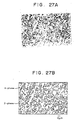
- FIG. 27A is a microscopic photograph showing crystal structure of a forging produced from the bar-shaped extrusion by forging on the conditions of cylindrical forging form, monoaxial compression, 50% forging ratio, forging temperature of 550°C and 20K/sec cooling rate after forging.
- FIG. 27B is a schematic drawing prepared on the basis of FIG. 27A.
- the brass shown in FIGs. 26A and 26B is a mixture of ⁇ and ⁇ phases which contains the ⁇ phase at a ratio ranging from 30% at the minimum to 80% at the maximum in the heating for forging, and in the average particle grain size of 15 ⁇ m or less, thus belonging to the " ⁇ + reinforced ⁇ type". As shown in FIGs. 27A and 27B, further this brass does not cause any change in the crystal grain size, ratio of the ⁇ phase to the ⁇ phase, and shapes of the crystal grains, and also does not cause cracks by the forging.
- FIG. 28A is a microscopic photograph showing crystal structure of a bar-shaped extrusion produced from brass composed of 58.7% by wt. of Cu, 2.3% by wt. of Sn, and the remaining percentage of Zn on the conditions of the extrusion temperature of 550°C, extrusion ratio of 50% and cooling rate of 30K/sec by forced air cooling after extrusion.
- FIG. 28B is a schematic drawing prepared on the basis of FIG. 28A.
- FIG. 29A is a microscopic photograph showing crystal structure of a forging produced from the bar-shaped extrusion by forging on the conditions of cylindrical forging form, monoaxial compression, 50% of forging ratio, forging temperature of 550°C and cooling rate after forging of 20K/sec.
- FIG. 29B is a schematic drawing prepared on the basis of FIG. 29A.
- the brass shown in FIG. 28 as well belongs to the " ⁇ + reinforced ⁇ type". Particularly, this brass did not cause cracks regardless of the fact that the Sn content of this brass widely exceeded the high limit of 1% by wt. at which brass in forging had been traditionally considered to cause cracks. This is supposed to be because the crystal grains are fine.
- microcrystallization of crystal grains is effective for obtaining good hot ductility. Further it is also effective for good hot ductility that, even when the crystal structure of the brass is a mixture of the ⁇ and ⁇ phases, the ratio of the ⁇ phase is in the range of from 30% to 80%. This is considered to be for the following reason:
- the hot forging and hot extrusion cause strain in the crystal structure by an external force. Microscopically this strain means that atomic arrangement in the crystal structure is in disturbed condition, i.e., atomic dislocation.
- dislocated atoms are rearranged to release or free the crystal structure from strain, and as a result good hot ductility is secured.
- the energy sources that cause the dynamic recrystallization are thermal energy by heating and strain by an external force. When subjected to an external force, mixed structure of the ⁇ and ⁇ phases cause dislocation in softer grains of the ⁇ phase by stress from harder grains of the ⁇ phase.
- the strain in the ⁇ phase concentrates on a part (perhaps because shift of ⁇ -phase grains subjected to dislocation is prevented by larger grains of the ⁇ phase). Contrarily, If the crystal grain size of the ⁇ phase is finer, the strain in the ⁇ phase is dispersed (perhaps because ⁇ -phase grains shift by grain boundary sliding caused on the boundary between the ⁇ and ⁇ phases). Since the dispersed strain has larger whole potential energy than that of local strain, recrystallization exceeds a threshold, thereby providing good ductility for the brass.
- Addition of Sn is also considered to contribute not only to improvement of the corrosion resistance of the ⁇ phase but also to acceleration of the recrystallization.
- the acceleration of the recrystallization improves ductility of the brass against an external force exerted at a high rate.
- FIG. 30 shows preferable conditions of four types of brass of this invention concerning their final crystal structure at room temperature, crystal structure in hot working (that is, in the recrystallization zone), and composition.
- FIG. 31 shows typical conditions for casting brass at the first step and for obtaining the final composition shown in FIG. 30 by hot-extruding the brass after the above-mentioned casting.
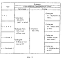
- FIG. 32 shows typical conditions of extrusion and forging when the final composition is obtained by hot-extruding and further hot-forging the brass.
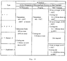
- FIG. 33 shows typical conditions of extrusion, forging and heat treatment when the final composition is obtained by hot-extruding, hot-forging and further heat-treating the brass.
- the numerical values in parentheses are particularly preferable values.
- FIGs. 30-33 the crystal structure, compositions and typical production methods of the brass according to this invention.
- the " ⁇ + ⁇ type" of brass has crystal structure of ⁇ + ⁇ type.
- the areal ratio of the ⁇ phase is 97-70% and that of the ⁇ phase is 3-30%, preferably that of the ⁇ phase is 95-70% and that of the ⁇ phase is 5-30%.
- the average grain size of the ⁇ phase is 15 ⁇ m or less, preferably 10 ⁇ m or less.
- the average grain size of the ⁇ phase (in this case, minor axis) is 8 ⁇ m or less, preferably 5 ⁇ m. In a microscopic photograph it can be observed that on the grain boundary of the ⁇ phase a thin layer of the ⁇ phase is formed.
- the Sn concentration of the ⁇ phase is 8% by wt. or more, e.g., 14-18% in examples 1-5 shown in FIGs. 2A-2C.
- the " ⁇ + ⁇ + ⁇ type" of brass has crystal structure of ⁇ + ⁇ + ⁇ type.
- the areal ratio of the ⁇ phase is 40-94% and respective areal ratios of the ⁇ and ⁇ phases are 3-30% For example, in examples 6-12 shown in FIGs. 2A-2C, the areal ratio of the ⁇ phase is 65-82.5%, that of the ⁇ phase is 9.8-13.4%, and that of the ⁇ phase is 4-24%.
- the average grain sizes of the ⁇ and ⁇ phases are 15 ⁇ m or less, preferably 5 ⁇ m or less.
- the average grain size of the ⁇ phase (in this case, minor axis) is 8 ⁇ m or less, preferably 5 ⁇ m or less.
- a thin layer (8 ⁇ m or less in thickness) of the ⁇ phase is formed so as to surround crystals of the ⁇ phase.
- the Sn concentration in the ⁇ phase is 8% by wt. or more, e.g., 11-13.4% in examples 6-12 shown in FIGs. 2A-2C.
- the " ⁇ + normal ⁇ type" of brass has crystal structure of ⁇ + ⁇ type.
- the areal ratio of the ⁇ phase is 23.1-25.6%.
- the average grain sizes of the ⁇ and ⁇ phases are 15 ⁇ m or less, preferably 5 ⁇ m or less.
- the " ⁇ + reinforced ⁇ type" of brass has crystal structure of ⁇ + ⁇ type.
- the areal ratio of the ⁇ phase is 15% or more, preferably 20% or more, and for example, 23-38% in examples 16-19 shown in FIGs. 2A-2C.
- the average grain sizes of the ⁇ and ⁇ phases are 15 ⁇ m or less, preferably 10 ⁇ m or less.
- the Sn concentration in the ⁇ phase is 1.5% by wt. or more, e.g., 2.5-7.1% by wt. in examples 16-19 shown in FIGs. 2A-2C.
- All the types of brass have crystal structure of ⁇ + ⁇ type, and the areal ratio of the ⁇ phase is 30-80%.
- the average crystal grain sizes of the ⁇ + ⁇ type are 15 ⁇ m or less, preferably 10 ⁇ m or less.
- the crystal grains of the ⁇ phase are substantially uniformly distributed.
- the ⁇ + ⁇ type" and " ⁇ + ⁇ + ⁇ type” of brass have apparent Zn contents of 37-46% by wt, preferably 38-46% by wt. in order to obtain good hot ductility.
- the overall Sn content is 0.9-7% by wt.
- the apparent Zn content is 37.8-44% by wt.
- the overall Sn content is 1.5-3.5% by wt.
- the ⁇ + normal ⁇ type" of brass has the apparent Zn content of 37-44% by wt, preferably 38-44% by wt. in order to obtain good hot ductility.
- the apparent Zn content is 41.8-44% by wt.
- the overall Sn content is less than 0.5% by wt.
- the ⁇ + reinforced ⁇ type" of brass has the apparent Zn content of 37-44% by wt, preferably 38-44% by wt. in order to obtain good hot ductility.
- the overall Sn content is 0.5-7% by wt.
- the apparent Zn content is 40.1-42.6% by wt.
- the overall Sn content is less than 0.8-3.6% by wt.
- the solidification rate at the time of casting is 5 ⁇ 10 1 to 10 5 K/sec, preferably 10 2 to 10 5 K/sec.
- the solidification rate of 10 5 K/sec is the high limit for preventing the brass from becoming amorphous.
- the cooling rate down to 400°C or below after the solidification is to be 5K/sec or more.
- the extrusion temperature is 480-650°C, preferably 480-600°C.
- the sectional reduction ratio (sinking ratio) is 90% or more, preferably 95% or more.
- the cooling rate until the temperature after extrusion is lowered to 400°C or below is 0.4-5K/sec for the " ⁇ + ⁇ type", 9.4-10K/sec for the " ⁇ + ⁇ + ⁇ type", 0.4°C or more for " ⁇ + normal ⁇ type", and 5-1000K for " ⁇ + reinforced ⁇ type”.
- the cooling rate is 0.8K (air cooling) when in examples shown in FIGs.
- Conditions of the hot extrusion are the same as described in (6) above except that regardless of the type of crystal structure the cooling rate after the extrusion is to be 4°C or more until the temperature is lowered to 400°C or below.
- the temperature for the hot forging is 480-750°C, and for example, 500-600°C in examples shown in FIGs. 2A-2C.
- the strain rate of the forging is preferably 1/sec or more.
- the cooling rate after the forging is the same as the cooling rate after the extrusion described in (6) above.
- Conditions of the hot extrusion are the same as described in (7) above.
- Conditions of the hot forging are the same as described in (7) above except that regardless of the type of crystal structure the cooling rate after the forging is to be 4°C or more until the temperature is lowered to 400°C or below.
- the heat treatment is not required for producing the " ⁇ + normal ⁇ type" (that is, when the hot forging is carried out on the above-mentioned condition, the final structure of the " ⁇ + normal ⁇ type” is obtained).
- the heat treatment temperature and the retaining time are 450-550°C and 30 sec or longer for the " ⁇ + ⁇ type", 450-550°C and 30 sec or longer for the " ⁇ + ⁇ + ⁇ type", and 475-550°C and 30 sec or longer for the " ⁇ + reinforced ⁇ type”.
- the cooling rate after the heat treatment is the same as that after the extrusion described in (6) above.
- the ⁇ + ⁇ + ⁇ , ⁇ + ⁇ , ⁇ + normal ⁇ , and ⁇ + reinforced ⁇ types of brass can be applied to products that have been so far made up of materials other than brass for such reasons as surface roughness, corrosion resistance, dimensional accuracy in addition to applications that have traditionally used brass as seen in water-contact parts, such as valves and faucets, metals for sanitary porcelain, different pipe fittings and couplings, pipes, gas fittings, building materials such as doors and knobs, electric household appliances.
- water-contact parts that can use the brass according to this invention, faucets, metal fittings for hot-water supply systems, toilet-seat hot-water washers, etc., water supply pipes, connection pipes, valves, etc. can be exemplified. The following explains some examples.
- FIG. 34 illustrates an example of faucet fitting using a brass extrusion of this invention.
- a pressure-resistant large body subjected to water pressure on the primary side is connected with a spout 25 through a small pressure-resistant fitting 23 on the secondary side.
- the minimum thickness of the body 21 is 0.2 mm or more, and the minimum thickness of the fitting and spout is 0.1 mm or more.
- a brass forging of this invention is used as an elbow pipe 29 connected to a water pipe 27.
- a brass forging of this invention is used as a connecting metal 33 for a shower hose
- a still further example shows a brass forging of this invention used for a fitting 41 in connection between pipes 35, 37 and 39.
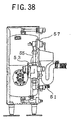
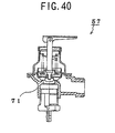
- FIGs. 38, 39, and 40 show brass parts of this invention used for a hot-water supply system.
- FIG. 38 is an overall sectional view of the hot-water supply system.
- a brass forging of this invention is used for a pressure reducing valve 53 connected to a water inlet pipe 51, and a bypass valve connected to a water feed valve 55 for water feed from the pressure reducing valve 53.
- a brass forging of this invention is used for a valve body 61 and valve stem 63 (hatched parts)
- a brass forging of this invention is used for a valve body 71 (a hatched part).
- a brass forging produced by the method of this invention has excellent corrosion resistance and acid resistance, and therefore when used for water-contact parts, the brass has scarce strength reduction due to secular change of the water-contact parts.
- a brass forging of this invention not only excels in corrosion resistance and acid resistance but also has high strength, and therefore it enables water contact parts to have thinner wall.
- the JIS of faucets stipulates pressure-resistant performance of 17.5 kg/cm 2 for pressure-resistant metal parts in water contact.
- the wall thickness of water-contact parts has to be decided by taking decrease of the wall thickness by taking secular corrosion into consideration in connection with this pressure-resistant performance. Hitherto the minimum wall thickness of cylindrical faucet metal parts of 100 mm in diameter has been decided to be 1.0-1.5 mm.
- a brass forging produced by the method of this invention can reduce the minimum wall thickness to 0.8-1.2 mm when used for these parts.
- a brass forging produced by the method of this invention has good machinability, so that the machining time can be shortened, and its high hot ductility secures formability in a short time by forging etc.
- High forgeability in a short time increases degrees of freedom in designing.
- the high hot ductility and the forgeability at such low temperature as 600°C or below improve precision and profile irregularity of forgings and prevents oxide films from being formed on forged surfaces.
- ⁇ + ⁇ + ⁇ , ⁇ + ⁇ , ⁇ +normal ⁇ and ⁇ +reinforced ⁇ types of a brass extrusion according to this invention have very wide applications including products that have been conventionally made of brass, metals other than brass as stainless steel, and nonmetallic materials. Applications include:
Abstract
Description
- This invention relates to a method of manufacturing metal products. This invention is related to Cu-Zn-based copper alloy, that is brass, and a method of manufacturing brass.
- Metals such as aluminum and stainless steel have been known to present 1000% or higher elongation. This excellent elongation is obtained because the strain is released by grain boundary sliding of crystal grains. The grain boundary sliding works most effectively when an external force of such a strain rate as 0.01/sec. This is why aluminum and stainless steel show high ductility when they undergo such low-rate external force. However, when an external force of a high strain rate exceeding 0.1/sec is given to crystal grains, the grain boundary sliding does not work effectively and crystal grains undergo substantial dislocation, thereby developing cracks in the metal.
- As known in the art, to avoid crack initiation by external high-rate force, metals may be recrystallized by thermal energy or a strain energy due to deformation in working (dynamic recrystallization). Dynamic recrystallization for improving ductility is practically employed in manufacturing metals such as brass.
- Conventional brass has realized 100% or a little higher elongation by a high-rate external force of a 0.1/sec strain rate. At present it is difficult, however, for the conventional art to realize further higher elongation. To realize higher elongation against an external high-rate force, the recrystallization rate needs to be increased. However, if metals are placed in such high-temperature condition as to increase the heat energy needed for recrystallization, crystal grains will coarsen before working force works to the grains and as a result dynamic recrystallization will not occur in working. Therefore, since the conventional working force is given at a lower temperature than the temperature above which crystal grains coarsen, enough energy to increase recrystallization rate is not achieved.
- Brass is applied to a wide variety of applications, and properties required to brass differ depending on the application. For example, brass for forging requires high ductility against an external high-rate force mentioned above. Brass applied to parts kept contact with water (valves, faucet fittings, etc.), requires high corrosion resistance and high erosion resistance to water. Furthermore, high strength and machinability are also required in various applications.
- Copper alloy known to have excellent corrosion resistance to water is Cu-Zn-Sn-based copper alloy (JIS C4641) or naval brass bar, and Cu-Zn-based copper alloy (JIS C6782) or high tensile brass bar. Corrosion resistance of brass mainly means resistance to dezincing. Because of the difference of ionization tendency of Cu and Zn, Zn is liable to dissolve in water faster than Cu and, as a result, the brass reduces its Zn content and loses strength with the lapse of time. Such phenomenon is called dezincing, which becomes the important problem when the brass is applied to water-contact parts.
- Improvement of the corrosion resistance disclosed by Examined Japanese Patent Publication No. Sho6158540, 1986, describes the brass which is made by adding Pb, Fe, Ni, Sb and P to Cu-Zn-Sn-based copper alloys and is substantially in the α phase. Improvement in the corrosion resistance disclosed by Laid-open Japanese Patent Publication No. Hei6108184, 1994, describes the brass in which a Cu-Zn-Sn-based copper alloy to which Pb, Fe, Ni, Sb and P are added is, after being subjected to hot extrusion or hot drawing, heat-treated at 500°C-600°C for 30 min - - 3 hours to obtain brass which is substantially in α phase. As mentioned above, to realize brass of good corrosion resistance, the conventional arts have produced brass which is substantially in a single phase of α phase without depositing the β phase, which is very inferior in corrosion resistance.
- However, the above-mentioned conventional brass which is substantially of the single α phase is inferior in mechanical strength and machinability. On the other hand, though the conventional brass having crystal structure of α+β type has good mechanical strength and machinability, it is inferior in corrosion resistance since the β phase is extremely inferior in corrosion resistance. In other words, in the conventional arts, it is difficult to manage to enhance corrosion resistance and mechanical strength as well as machinability simultaneously.
- JP-A-3110042 discloses a method for producing brass with improved hot rolling workability. The brass has a Zn content of 25-45wt%. From a melt temperature of ≥ 1050°C the brass is cooled at a rate of ≥ 100°C/s
- It is an object of the invention to provide a production method for brass.
- According to the present invention, there is provided a method for producing brass extrusions as defined in
claim 1 below. The dependent claims are directed to optional or preferred technical features. - Disclosed herein is a metal so constructed that, when it is given an external force and deformed, the strain in the crystal structure will disperses. In the metal, the strain energy caused by the deformation can work as an energy source for recrystallization. As a result, when an external high-rate force is given to the metal, the strain in the crystal structure disperses without concentrating locally, thereby producing a large strain energy which enables recrystallization and prevents crystal grains from dislocating. Thus a metal that presents high ductility by an external high-rate force is provided.
- Also disclosed herein is a method of manufacturing metal products - which contains hot- working process of metal on conditions that if strain energy of metal crystals deformed by an external force in hot working is denoted by SE, and heat energy given to the metal crystals by heating in hot working is denoted by TE;
SE+TE > Minimum energy necessary for recrystallization of deformed metal crystal
TE < Energy necessary for a crystal grain to coarsen under the condition of no external-force. - In such a production method, a metal in hot working is not heated up to such high temperature as the crystal grains coarsen so as to reduce the ductility. Instead, the method offers a way to satisfy the conditions needed for the strain energy in metal caused by deformation due to an external force to become large enough so that effective recrystallization takes place even at a relatively low temperature (energy due to deformation is considered potential energy caused by dislocation). In practice, such conditions can be adjusted so that the metal crystal structure to be subjected to hot working develops strain dispersedly when subjected to an external force (dispersion of strain is microscopically considered to be dispersion of dislocation ). As a result, crystal grains do not coarsen when heated, and dynamic recrystallization takes place effectively in a metal when an external force in working is given, thus realizing high ductility to an external high-rate force.
- One type of crystal structure that develops strain when given an external force is a mixture of relatively soft and hard crystals of sufficiently fine grain size. In such crystal structure, when given an external force, soft crystals deform (supposedly due to the grain boundary sliding between soft and hard crystals), and the deformed soft crystals migrate and disperse. The crystal structure mentioned above can be realized by an alloy which contains two kinds of metal elements and deposit a soft and hard crystal phase, typically brass, which is an alloy of Cu and Zn. Embodied examples of an alloy of this invention are α+β-, α+β+γ- and α+γ- type brass of fine crystal grains of 15 µm or smaller in diameter.
- To accomplish effective results, a third element contributing to accelerate recrystallization rate (to accelerate nucleation rate for recrystallization) may be solid-dissolved in soft crystals of the alloy made of two kinds of metals as mentioned above. The typical third element, for example, is Sn in brass the atomic radius of which resembles closely to the above-mentioned two kinds of metal elements so that substitutional solid solution in soft crystals may take place.
- The present method proposes to provide brass possessing α+β crystal structure within the temperature range for recrystallization, and also satisfying the following conditions within the recrystallization temperature range :
- (A1) Areal ratio of β phase is 30% - 80%;
- (A2) Average crystal grain sizes of α and β phases are 15 µm or smaller, preferably smaller than 10 µm in; and
- (A3) The α phase exists dispersedly.
-
- A desirable example of such a brass has the following high hot ductility within the recrystallization temperature range:
- (1) The brass is not damaged when given 100% strain at a strain rate of 1/sec;
- (2) The brass is not damaged when given 200% strain at a strain rate of 0.1/sec,
- (3) The brass is not damaged when given larger than 200% strain at a strain rate of 0.01/sec; or
- (4) The brass is not damaged when given larger than 600% strain at a strain rate of 0.001/sec.
-
- The conventional brass cannot realize such high elongation percentage as mentioned above. Also, the conventional superplastic materials (e.g. aluminum and stainless steel) are not provided with good ductility against high-rate strain as in (1) and (2) above.
- The brasses discussed below can be roughly classified into four types called as follows in this specification: "α+γ type," "α+β+γ type, " "α+normal β type, " and "α+ reinforced β type. "
- The "α+γ type" brass possesses α+γ crystal-structure in room temperature, and also in room temperature satisfies the following conditions:
- (B1) The areal ratio of γ phase is 3% - 30%, preferably 5%-30%;
- (B2) Average crystal grain size of the α phase is 15 µm or smaller, preferably 10 µm or smaller;
- (B3) Average crystal grain size of the γ phase is 8 µm or smaller, preferably 5 µm or smaller; and
- (B4) The above-mentioned γ phase exists on the α phase grain boundary. This type of brass excels in machinability.
-
- The "α+β+γ type" brass possesses α+β+γ crystal-structure at room temperature, and also at room temperature satisfies the following conditions:
- (B1) The areal ratio of the α phase is 40% - 94%;
- (B2) The areal ratios of both the β and γ phases are 3% - 30% ;
- (B3) Average crystal grain sizes of β and γ phases are 15 µm or smaller, preferably 10 µm or smaller; and
- (B4) Average crystal grain size of the γ phase is 8 µm or smaller, preferably 5 µm or smaller. This type of brass also excels in machinability.
-
- Further, this type of brass may preferably be manufactured to satisfy the following conditions at room temperature:
- (B5) The γ phase contains 8% by wt. or more Sn, and
- (B6) The β phase is surrounded by the γ phase mentioned above. The brass satisfying the above conditions comes to excel in corrosive resistance and stress corrosion cracking resistance (SCC resistance).
-
- The "α + normal β type" brass possesses α+β crystal-structure at room temperature, and also at room temperature satisfies the following conditions:
- (B1) The areal ratio of β phase is 20% or larger, preferably 25% or larger, and
- (B2) Average crystal grain sizes of the β and γ phases are 15 µm or smaller, preferably 10 µm or smaller. This type of brass excels in machinability and strength.
-
- The "α + reinforced β type" brass possesses α+β crystal-structure at room temperature, and also at room temperature satisfies the following conditions:
- (B1) The areal ratio of the β phase is 15% or larger, preferably 20% or larger,
- (B2) Average crystal grain sizes of the α and β phases are 15 µm or smaller, preferably 10 µm or smaller, and
- (B3) The β phase contains 1.5% by wt. or more Sn. This type of brass excels in machinability corrosion resistance and SCC resistance.
-
- In all types, satisfactory examples present such good hot ductility that does not cause any damage even if 400% strain at a strain rate of 0.01/sec is given within the recrystallization temperature range. A satisfactory example also shows furthermore excellent properties in room temperature as described in (1) - (3) below:
- Machining resistance index based on, as the reference, the free-cutting brass bar conforming to JIS (Japanese Industrial Standard) C 3604 is 80 or higher.
- Through dezincing tests conducted in accordance with the technical standard T-303 of JBMA (Japan Brass Makers Association), corrosion resistance was confirmed as follows: If the direction of the maximum dezinking penetration depth is parallel with the working direction, the maximum dezinking penetration depth is not deeper than 100 µm, and if the direction of the maximum dezinking penetration depth is rectangular to the working direction, the maximum dezinking penetration depth is not deeper than 70 µm.
- After a cylindrical specimen of brass of this invention is exposed to an ammoniacal atmosphere over 14% ammonia water and then a load is applied to the specimen for 24 hours, the maximum stress below which the specimen does not crack is not lower than 180 N/mm2.
- No conventional metals can satisfy the above-mentioned conditions. For example, SPZ (zinc aluminum) and aluminum are, when placed in water, inferior in corrosion resistance, and particularly aluminum develops pitting. In addition, because these metals are tough, they are also inferior in machinability.
- The present invention proposes to manufacture brass with a step of manufacturing brass castings by performing casting under the following conditions:
- (1) Apparent Zn content in material composition is 37%-46% by wt.,
- (2) The solidification rate after casting is 5 x 101-105K/sec, preferably 102 - 105K/sec, and
- (3) The cooling rate after solidification is, until the temperature drops to 400°C or below, 5K/sec or higher.
-
- The brass castings produced by the above-mentioned method show high hot ductility,
- The production method of this invention further contains the step of making brass extrusions by performing, after performing casting as mentioned above, hot extrusion of the above-mentioned brass castings within the temperature range of 480°C-650°C, preferably 480°C-600°C. The cooling rate after the hot extrusion is, preferably 0.4K/sec or higher, until the temperature is lowered to 400°C or below.
- A method of manufacturing the brass according to this invention contains a step of producing brass extrusions by hot-extruding brass the apparent Zn content of which is 37%-46% by wt. under the following conditions:
- (1) Temperature in the extrusion is 480°C-650°C, preferably 480°C-600°C, and
- (2) Reduction in the extrusion is 90% or higher, preferably 95% or higher. The cooling rate after hot extrusion is preferably 0.4K/sec or higher, until the temperature is lowered to 400°C or below. Because of this rapid cooling, crystal grains do not coarsen even after the cooling, and thus the crystal structure having such finer crystal grains as 15 µm or smaller, which is one of the technical effects achievable with this invention, can be obtained.
-
- This production method may further contain the step of making brass forgings by reheating and hot-forging the above-mentioned brass extrusions within the temperature range of 480°C-750°C. The strain rate in hot-forging is preferably 1/sec or higher. Such rapid hot-forging will not increase the crystal grain size. The cooling rate after hot forging is preferably 0.4K/sec or higher, until the temperature is lower to 400°C or below. Due to this rapid cooling, crystal grains do not increase in diameter even after the cooling, thus remaining as fine crystal grains of 15 µm or smaller size.
- For producing the "α+γ type" of brass according to the above-mentioned production method, when the Sn content of brass is 0.9 - 7% by wt., cooling conditions of 0.4 - 5K/sec may be selected until cooling rate after hot extrusion or hot forging is lowered to 400°C or below. Alternatively, when the Sn content of brass material is also 0.9 - 7% by wt., following the hot forging step, a heat-treatment step may be added so that the brass forging can be heated and kept at 400-550°C for 30 sec or longer and then cooled at a cooling rate of 0.4-5K/sec until its temperature is lowered to 400°C or below.
- For producing "α+β+γ type" of brass according to the above-mentioned production method, when the Sn content of the brass is 0.9 - 7% by wt., a cooling condition of 0.4 - 10K/sec may be selected until the temperature after hot extrusion or hot forging is lowered to 400°C or below. Alternatively, instead of adjusting the cooling rate as mentioned above, a heat-treatment step following the hot forging process may be added so that the brass forging can be heated and kept at 450-550°C for 30 sec or longer and then cooled at a cooling rate of 0.4-10K/sec until its temperature is lowered to 400°C or below.
- For producing the "α + reinforced β type" of brass according to the above-mentioned production method, when the Sn content of the brass is 0.5-7% by wt. and the apparent Zn content is 37-44% by wt., a cooling condition of 5 - 1000K/sec may be selected until the cooling rate after hot extrusion or hot forging is lowered to 400°C or below. Alternatively, instead of adjusting the cooling rate as mentioned above, a heat-treatment step following the hot forging process may be added so that the brass forging can be heated and kept at 475-550°C for 30 sec or longer and then cooled at a cooling rate of 5-1000K/sec or higher until its temperature is lowered to 400°C or below.
- A further method of producing brass contains the step of: heating and then cooling the brass of the apparent Zn content of 37-46% by wt., and controlling at least any one of heating temperature, heat retaining time and cooling rate so that the crystal structure of the cooled brass can be selected out of the α+β, α+β+γ, and α+γ types. For example, under conditions of the same heating temperature and heat retaining time, the cooling rate may be controlled to the lowest rate for obtaining the α+γ type, and to a higher rate for obtaining the α+β+γ type. and to the highest rate for obtaining the α+β type.
- The brass produced according to this invention can exhibit good machinability and mechanical strength. The machining resistance index based, as a reference, on the free cutting brass bar conforming to JIS (Japanese Industrial Standard) C 3604 can be 80 or higher, and o.2% yield strength or the yield stress can be 300 N/mm2 or mores Conventionally, no copper alloy has been provided with such good machinability and strength. For example, although bronze has cutting resistance index of 80 or more, its 2% yield strength is only about 80 N/mm2 and its tensile strength is only about 220 N/mm2. It is generally difficult to improve the strength of bronze because the copper content of bronze is 79% or more. One of the ways of improving the strength of bronze is to increase the Sn content of bronze. However, bronze of a higher Sn content often develops a defect called shrinkage cavities (foams in solidification contraction) in casting, thus reducing strength. On the contrary, brass produced by the method of this invention maintain an adequate balance between copper excelling in corrosion resistance and zinc excelling in machinability, providing improved machinability and strength.
- The brass produced by the method of this invention are provided with the following stress corrosion cracking resistance: When a cylindrical specimen of such brass is exposed to an ammoniacal atmosphere over 14% ammonia water for 24 hours under a load, the maximum stress under which the specimen does not crack is 180 N/mm2 or more. For improving SCC resistance, improvements in strength and corrosion resistance are essential (though other factors are also required). The SCC resistance is improved in this invention by taking advantage of excellent corrosion resistance of copper. Incidentally, bronze is less durable to stress and causes plastic deformation by stress of about 100 N/mm2.
- The brass produced by the method of this invention can have the following good machinability and corrosion resistance: Its machining resistance index based, as the reference, on the free-cutting brass bar is 80 or higher, and when a dezinking corrosion test is conducted in accordance with a technical standard T-303 of JBMA, the maximum dezinking penetration depth is 100 µm or less if the direction of the maximum dezinking penetration depth is parallel with the working direction, and 70 µm or less if the direction of the maximum dezinking penetration depth is rectangular to the working direction. Incidentally, free-cutting brass bars are inferior in corrosion resistance, and when a dezinking test is conducted as mentioned above, the maximum dezinking penetration depth reaches approximately 200 µm.
- One of the ways of improving machinability of brass is to reduce the average crystal grain size to 15 µm or smaller, preferably 10 µm or smaller. In addition, it is desirable to adjust the crystal structure so that it contains the α phase and parts that exists between the grain boundary of the α phase and is softer or harder than the α phase. The parts softer than the α phase are composed of such metals as Pb and Bi, that is, metals other than the metal constituting the α phase. The parts harder than the α phase are composed of the β or γ phases, intermetallic compounds such as FeSi and FeP, or oxides of Cu and Mg. When crystal structure of the α+β type is compared to that of the α+γ type, the latter shows higher machinability than the former, because the difference of hardness between two phases is larger in the α+γ type of crystal structure than in the α+β type of crystal structure.
- To improve the corrosion resistance as well as machinability, brass may be produced by the following method. For example, for the α+γ type of crystal structure, it is effective to make the γ phase contain Sn preferably in a
quantity 8% by wt. or more. For the α+β type of crystal structure, it is effective to make the β phase contain third elements (e.g. Sn, Si, Al, Sb, Ge or Ga) for the purpose of improving corrosion resistance. To make the β phase contain Sn, the Sn concentration in the phase is preferably 1.5% by wt. or higher. Further, it is also effective to produce crystal structure composed of the α phase, β phase and parts which surround crystal grains of the β phase and offers higher corrosion resistance than that of the β phase. The parts which offer higher corrosion resistance than the β phase does is, for example, the γ phase that contains Sn of 8% by wt. or more. For the α+β+γ type of crystal structure, it is desirable to make the average minor axis of crystal grains in theγ phase 8 µm or smaller so that the structure does not develop brittleness of the γ phase. - The brass having machinability and corrosion resistance improved by following the teachings of this specification is applicable to a variety of applications, especially to water piping parts. Because the average crystal grain size of the brass made available by this invention is small, the brass is rather inferior in cold ductility. However, for applications to water piping parts, which do not require such high cold ductility as martensite and shape memory alloys possess, such brass can fully satisfy the product quality required for the parts.
- This invention makes available a wide variety of products using brass.
- The foregoing features of the invention, as well as the invention itself, may be more fully understood from the following detailed description with reference to the attached drawings, in which:
- FIG. 1 is a table presenting properties of three crystal phases of brass, pure Cu, pure Zn and pure Sn;
- FIGs. 2A-2C are tables presenting composition, crystal structure and properties of examples of this invention and examples of conventional brass as references;
- FIG. 3 is a flow diagram illustrating an example of production process of brass product;
- FIG. 4 is a table presenting casting and hot-extrusion conditions of two examples of brass production method of this invention and of a conventional method;
- FIG. 5 is a table presenting hot-forging conditions and crystal structure in two examples of brass production method of this invention and of a conventional method;
- FIG. 6 is a graph showing ductility test results (unit strain and strain rate) within the recrystallization temperature zone;
- FIG. 7 is a table presenting machinability test results;
- FIG. 8 is a perspective view illustrating a machinability test method;
- FIG. 9 is a graph showing erosion-resistance test results;
- FIG. 10 is a sectional view illustrating a erosion-resistance test method;
- FIG. 11 is a sectional view illustrating a SCC resistance test method;
- FIG. 12 is a table presenting SCC resistance test results;
- FIG. 13 is a table presenting composition and corrosion-resistance test results of samples relating to the "α+reinforced β type" of brass;
- FIG. 14 is a graph showing the relationship between Sn concentration in the β phase and the cooling time down to 400°C;
- FIG. 15 is a table presenting the effectiveness of heat treatment for the "α+reinforced β type" of brass of this invention;
- FIG. 16A is a microscopic photograph showing crystal structure of an example of the "α + γ type" of brass of this invention;
- FIG. 16B is a grain structure drawing prepared based on FIG 16A;
- FIG. 17A is a microscopic photograph showing crystal structure of an example of the "α + β + γ type" of brass of this invention;
- FIG. 17B is a schematic drawing of the crystal structure prepared based on FIG 17A;
- FIG. 18 is a table presenting composition and corrosion-resistance test results of samples relating to the "α+γ type" and "α+β+γ type" of brass of this invention;
- FIG. 19 is a flow diagram illustrating an example of manufacturing process of parts contacting with water prepared using the "α+γ type" and "α+β+γ type" of the brass of this invention;
- FIG. 20 is a flow diagram illustrating an example of manufacturing process of water-contact parts prepared using conventional brass;
- FIG. 21 is a table presenting the effectiveness of heat treatment for the "α + β type" and "α + β + γ type" of brass of this invention;
- FIG. 22A is a microscopic photograph showing crystal structure of brass for forging casted at a cooling rate of 19K/sec after casting;
- FIG. 22B is a schematic drawing of crystal structure prepared based on FIG 22A;
- FIG. 23A is a microscopic photograph in which a part of FIG 22A is enlarged;
- FIG. 23B is a schematic drawing of crystal structure prepared based on FIG 23A;
- FIG. 24A is a microscopic photograph showing crystal structure of brass for forging casted at a cooling rate of 1.3K/sec after casting;
- FIG. 24B is a schematic drawing prepared based on FIG 24A;
- FIG. 25A is a microscopic photograph in which a part of FIG 24A is enlarged;
- FIG. 25B is a schematic drawing of crystal structure prepared based on FIG 25A;
- FIG. 26A is a microscopic photograph showing crystal structure of a brass billet for forging prepared by hot-extruding brass having Sn content of 1.9% by wt. and then cooling the brass at a cooling rate of 30K/sec;
- FIG. 26B is a schematic drawing of crystal structure prepared based on FIG 26A;
- FIG. 27A is a microscopic photograph showing crystal structure of a brass forging prepared by hot-forging a brass billet shown in FIG. 26A and then cooling the forging at a cooling rate of 20K/sec;
- FIG. 27B is a schematic drawing of crystal structure prepared based on FIG 27A;
- FIG. 28A is a microscopic photograph showing crystal structure of a brass billet for forging prepared by hot-extruding brass with Sn content of 2.3% by wt. and then cooling the brass at a cooling rate of 30K/sec;
- FIG. 28B is a schematic drawing of crystal structure prepared based on FIG 28A;
- FIG. 29A is a microscopic photograph showing crystal structure of a brass forging prepared by hot-forging a brass billet shown in FIG. 28A and then cooling the forging at a cooling rate of 20K/sec;
- FIG. 29B is a schematic drawing of crystal structure prepared based on FIG 29A;
- FIG. 30B is a table presenting preferable conditions of crystal structure and composition of the brass of this invention;
- FIG. 31 is a table presenting preferable conditions of casting and hot-extrusion when the brass of this invention is finally produced by hot extrusion;
- FIG. 32 is a table presenting preferable hot-extrusion and hot-forging conditions when the brass of this invention is finally produced by hot forging;
- FIG. 33 is a table presenting preferable conditions of hot extrusion, hot forging and heat treatment when the brass of this invention is finally produced by heat treatment;
- FIG. 34 is a perspective view of an example of faucet fittings to which the brass of this invention is applied;
- FIG. 35 is a sectional view of an example of water pipe to which brass of this invention is applied;
- FIG. 36 is a sectional view of another example of water pipe to which the brass of this invention is applied;
- FIG. 37 is a sectional view of a further example of water pipe to which the brass of this invention is applied;
- FIG. 38 is a schematic side-view showing an example of a hot-water supply system provided with reducing valve and bypass valve to which the brass of this invention is applied;
- FIG. 39 is a sectional view showing a reducing valve of the hot-water supply system of FIG. 38; and
- FIG. 40 is a sectional view showing a bypass valve of the hot-water supply system of FIG. 38.
-
- Applications of copper alloys of Cu-Zn system cover a wide range, including water contact parts such as faucets and water supply pipes, electric household appliances, mechanical parts, architectural materials, gas fittings, and optical instrument parts. For these kinds of copper alloys, it is required to excel not only in general properties, such as mechanical strength, cold rollability, hardness, machinability, and polishability, but also in different properties required as water contact parts, such as corrosion resistance, erosion resistance, and resistance to stress corrosion cracking.
- One principle of this invention attaches importance for improving the above-mentioned properties to properties of crystal phases of Cu-Zn alloys. As the crystal phase present, three phases, α, β and γ, have been known so far. The γ phase excels in corrosion resistance and mechanical strength, but it has not been tried to utilize such properties positively because of its high brittleness. The β phase has low corrosion resistance and has been considered to be unsuitable to water contact parts. The α phase excels in corrosion resistance and cold ductility but is inferior in strength and machinability. As mentioned above, properties of respective phases have been rendered a fixed idea, and no positive attempt to alter properties of crystal phases has so far been made. In this situation, the present inventors elucidated importance of the crystal grain size as a factor that affects the above-mentioned different properties as a result of concentrated studies on such factors. These studies made it clear, in the first place, that properties of brass can be altered by effective utilization of the γ phase, secondly that properties of brass can be improved in particular by the β phase, and thirdly that properties of brass can be improved by optimizing the crystal grain size as well.
- As an actual means for depositing the γ phase and altering properties of the β phases, addition of Sn can be adopted. However, the addition of Sn is unsuitable to brass for forging because it lowers hot ductility of the brass. To solve this problem, the inventors conducted further studies on the hot ductility of alloys. As a result, it was proved fourthly that optimization of the grain size improves the hot ductility, and fifthly that optimization of the mixing ratio of the α and β phases secures dynamic recrystallization of the β phase, thereby improving the hot ductility.
- The embodiments of this invention employ the above-mentioned study results. It will be useful to describe properties of the three above-mentioned crystal phases before describing embodiments of this invention. FIG. 1 shows properties of three phases which appear in Cu-Zn alloys and those of pure Cu, Zn and Sn.
- As understandable from FIG. 1, pure Cu is inferior in yield strength and machinability (easiness to be machined) although it excels in corrosion resistance, ductility at room temperature and cold forgeability (easiness to be cold-forged). Instead, a Cu-Zn alloy to which Zn is added is conventionally used for wide range of applications. The Cu-Zn alloys come to differ in crystal structure by quantity of Zn to be added. When the apparent Zn content of a Cu-Zn alloy is 37% or less by weight, the crystal structure becomes a single α phase, and when the apparent Zn content is larger than 37%, the β phase appears in the crystal structure of the alloy (as α+β or β type). When the apparent Zn content is increased furthermore, the γ phase appears (as α+β+γ, α+γ, or β+γ type or single γ phase). Even when the true Zn content is low, the apparent Zn content increases and the γ phase appears if Sn (having Zn equivalent of 2) is added and the alloy is subjected to a special heat treatment. Here the term "apparent Zn content" means "[(B+t·Q)/(A+B+t·Q)]×100", where A is the Cu content (% by wt.), B is the Zn content (% by wt.), t is Zn equivalent (% by wt.) of an added third element, for example, Sn, and Q is the content of the third element (% by wt.).
- Although the single α phase excels in corrosion resistance and cold forgeability, it is inferior in yield strength and machinability. Addition of Sn can improve the corrosion resistance and yield strength of the Cu-Zn alloys, but the 2% by wt or more addition of Sn tends to make the alloys brittle. The β phase has properties approximately contrary to the α phase in that the β phase excels in yield strength, hot forgeability (easiness to be hot-forged) and machinability although it is inferior in corrosion resistance and cold forgeability. One knowledge the inventors obtained is that addition of Sn to crystal grains of the β phase improves corrosion resistance and yield strength; particularly the corrosion resistance is improved to a degree nearly comparable to the alloy of the single α phase. The γ phase appears when Sn is added in a specific quantity or more to the Cu alloy. The γ phase excels in corrosion resistance and yield strength although it is brittle.
- In this description the "corrosion resistance" of copper alloys means mainly resistance to dezinking corrosion. The dezinking corrosion is defined as such a phenomenon that because of difference between Cu and Zn in the ionization tendency, Zn is eluted into water earlier than other elements, thus decreasing the strength of the alloy with the lapse of time. This is a problem confronted when the Cu-Zn alloy is used.
- In the Cu-Zn alloys (brass) herein described crystal phases that have different properties (including modified properties) as described above are appropriately combined, and also the crystal grain size is optimized. FIGs. 2A-2C show compositions and properties of 19 examples of brass extrusions made according to thi invention in comparison with brass (as references) according to conventional technology.
- Features of crystal structure of examples 1-19 are described below. In examples 1-5 the alloys have crystal structure of α+γ type, whose crystal grains are microcrystallized (to 15 µm or smaller), and the γ phase having improved properties is effectively utilized. In examples 6-12 the alloys have crystal structure of α+β +γ type, whose crystal grains are microcrystallized, and the β and γ phases which have improved properties are effectively utilized. Examples 13-15 have crystal structure of α+β type, whose crystal grains are microcrystallized. Examples 16-19 have crystal structure of α+β type, whose crystal grains are microcrystallized, and their β phase has properties improved by addition of Sn. Furthermore, in these examples 1-19, the ratio of respective crystal phases has been appropriately adjusted. Details of crystal structure of these examples are described later.
- The alloys of examples 1-19 were produced by casting brass samples having compositions shown in FIG. 2A under the production conditions according to the principles of this invention, hot-extruding these samples, and then hot-forging the extrusions (the actual production flow is shown in FIG. 3). The heat treatment conditions shown in FIGs. 2A-2C are casting temperatures and cooling methods. The cooling rate of air cooling is 0.8K/sec, and that of water cooling is 100K/sec.
- In FIGs 2A-2C are listed as properties "0.2% yield strength (N/mm2)" (tensile stress causing permanent elongation of 2%), "cold ductility (%)" (ductility in a cold working zone), "hardness (HV)", "hot ductility" (ductility in a hot working temperature zone, i.e. in a recrystallization temperature zone), "cutting resistance index", "corrosion resistance", "erosion resistance" and "stress corrosion cracking resistance" (SCC resistance).
- In FIGs. 2A-2C evaluation of respective properties are marked. As to "0.2% yield strength", 300 N/mm2 was evaluated as poor (×), 300 N/mm2 or more and less than 35 N/mm3 as good (o), and 350 N/mm2 or more as excellent (©). As to the "hot ductility", if the maximum strain of a sample specimen was less than 100% when the specimen was subjected to a tensile test at a strain rate of 100 (/sec), it was evaluated as poor (×), and if the maximum strain was 100% or more, it was evaluated as good (o). As to the "cutting resistance index", if it was less than 80% with reference to free cutting brass bars (JIS C 3604) as a result of a cutting test described later, it was evaluated as poor (×), and if the index was 80% or more, it was evaluated as poor (×).
- The "corrosion resistance" was evaluated in accordance with judgment criteria shown by a technical standard (JBMA T-303) of Japan Brass Makers Association on the result of dezinking tests conducted in accordance with the JBMA T-303. That is, in the case where the direction of dezinking penetration depth is parallel with the working direction, the maximum dezinking depth of 100 µm or less was evaluated as good (o), and in the case where the direction of dezinking penetration depth is rectangular to the working direction, the maximum dezinking depth of 70 µm or less was evaluated as good (o). The results that do not satisfy these criteria was decided as poor (×).
- The "erosion resistance" was evaluated as good (o) when the tightening torque required for preventing the sample from leakage after the lapse of 1500 hours under the test conditions described later was less than 0.8 N·m, and as poor (×) when the tightening torque was 8% or more. The stress corrosion cracking resistance was evaluated as good (o) when the sample did not crack after the lapse of 24 hours under the test conditions described later, and as poor (×) when the sample cracked on the same condition as above.
- As seen in FIGs. 2A-2C, samples 1-5 were evaluated as good (o) or excellent (©) as to the yield strength, cold ductility, corrosion resistance, erosion resistance and stress corrosion cracking resistance. Examples 1 and 2 were evaluated as poor (×) as to machinability, and such evaluation is supposed to be for the reason that both the samples did not satisfy the optimum conditions where the β phase is to be 3% or more and the γ phase is to be 5% or more. Hot ductility of example 1 was also evaluated as poor (×); this evaluation is supposed to be for the reason that in the hot working the β phase did not reach 30% because the apparent Zn content was less than 38%.
- All the properties of examples 6-12 were evaluated as good (o) or excellent (©).
- Except the corrosion resistance and erosion resistance, all properties of examples 13-15 were evaluated as good (o) or excellent (©). The evaluation results of corrosion resistance and erosion resistance of examples 13-15 as poor (×) is supposed to be for the reason that these samples do not contain the γ phase, and that the Sn concentration in their β phase does not reach 1.5% by wt.
- All the properties of examples 16-19 were evaluated as good (o) or excellent (©).
- Advantages of examples of this invention are described below particularly in relationship to "hot ductility", "cutting resistance index", "erosion resistance", and "stress corrosion cracking".
- First, advantages of examples of this invention in the aspect of the "hot ductility" are described. Good ductility is one of the most important properties of billets supplied for hot working such as hot forging. FIG. 1 shows one example of a production process using hot forging for brass products.
- At the first step, a mixture of electrolytic copper, electrolytic zinc and scraps is melted and cast into an intermediate form. In the
next step 2, the formed castings are rapidly cooled and extruded in the form of bar- or wire rod-shaped billets. In thenext step 3, the bar- or wire rod-shaped billets are subjected to cold drawing, annealing and pickling. Then the billets are cut to a predetermined length. - In the
subsequent step 4, the billets are heated for securing properties suitable for forging in thenext step 5. Instep 5, the hot billets are set into forging dies, and forged. Then, as preparation for progressing to step 6, the forgings are cooled. After the cooling, the forgings are pickled and shot-blasted to remove the thin oxide coating formed on the surfaces, and deburred. In thelast step 7, through working of cutting, grinding and plating, final products are obtained. FIGs. 4 and 5 compare two examples of the production methods of this invention (methods - In FIG. 4, the "apparent Zn content" is involved in the mixing ratio of the materials melted at
step 1 shown in FIG. 1, the "solidification rate at casting" and "cooling rate after casting" are involved in casting conditions atstep 1, and the "extrusion temperature" and "cooling after extrusion" are involved in conditions of hot extrusion atstep 2. In FIG. 5, the "grain size" means that of the billets after hot extrusion at step 2 (and also the crystal grain size of final products in this invention); the "β-phase ratio", "forging temperature" and "strain and strain rate" are involved in forging condition atstep 5; and the "yield strength" and "α-, β-, and γ-phase ratios after forging" mean those of the products finished atstep 7. - As shown in FIG. 4, as compared with the conventional method, the apparent Zn content of
methods - These billets prepared by
methods methods methods - FIG. 6 shows hot ductility of two kinds of billets, one produced by a method of this invention and the other produced by the conventional method (actually example 10 and
reference 4, which are shown in FIGs, 2A-2C) in the forging temperature zone. The abscissa shows the strain rate (sec-1), and the ordinate shows strain εL (%). Example 10 is obviously superior in hot ductility toreference 4. - Referring now to FIG. 7, advantages of examples of this invention in the "cutting resistance index are described. FIG. 7 shows results of cutting tests conducted on
reference 3, examples 8, 10 and 11, free cutting brass bars (JIS C 3604), and brass of single σ phase. As depicted in FIG. 8, a main component force Fv was measured while cutting the circumferential surface of a round-bar sample 1 with a lath at two different speeds of 100 and 400 m/min. The cutting resistance index of each sample is expressed as percentage of a main component force of a free cutting brass bar which has been said to have the best machinability, to the main component force of each sample. - As shown in FIG. 7, the cutting resistance indexes of example 8, 10 and 11 reach near 90% of that of the free cutting brass bar having the best machinability with the results better than that of
reference 3 and the single α-phase brass bar. - Referring now to FIGs. 9 and 10, advantages of examples of this invention in the "erosion resistance" are described. FIG. 9 shows results of erosion resistance tests on examples 8 and 11 and
reference 4 shown in FIGS. 2A-2C, and FIG. 10 portrays the method of erosion resistance tests. As shown in FIG. 10, the erosion resistance tests were conducted using acylindrical sample 5 having an orifice inside. After water was passed through the orifice at a flow velocity of 40 m/sec for a predetermined period of time, tightening torque required for tightening adisk seat 9 to seal theorifice 7 under hydraulic pressure of 4.9 × 10⁵ Pa (5 kg/cm2) was determined. As shown in FIG. 9, it can be seen that examples 8 and 11 have higher erosion resistance than that ofreference 4. - Referring now to FIGs. 11 and 12, advantages of examples of this invention in the "strain corrosion cracking (SCC) resistance" are described.
- In the SCC resistance test, a cylindrical sample placed in a
glass desiccator 11 as shown in FIG. 11 was exposed to an atmosphere of NH3 vapor for 24 hours, and then checked the sample on cracking. Fig. 12 shows test results (relationship between main stress and cracking) of examples 8, 11 and 15, andreference 4. From FIG. 9, it is realized that examples 8, 11 and 15 have higher SCC resistance than that ofreference 4. - As described above, examples 1-19 of this invention shown in FIGs, 2A-2C have good properties. As in the preceding descriptions, examples 16-19 have properties improved by microcrystallizing the crystal structure of α + β type (to 15 µm or finer) and also by adding Sn to the β phase, and this type of brass according to this invention is hereinafter referred to as "α + reinforced β type". Examples 1-5 have properties improved by microcrystallizing the crystal grain size in the crystal structure of α+γ type and also by utilizing the γ phase. This type of brass is hereinafter referred to as "α+γ type." Examples 6-12 have properties improved by microcrystallizing the crystal grain size in the crystal structure of α + β + γ type and also by utilizing the γ phase. This type of brass is hereinafter referred to as "α + β + γ type." Examples 13-15 have properties improved by microcrystallizing the crystal grain size in the crystal structure of α + β type. This type of brass is hereinafter referred to as "α + normal β type."
- The method of production and crystal structure of the above-mentioned three types of crystal structure of brass according to this invention are described below.
- Referring now FIG. 13, the "α+reinforced β type" is first described. This type of crystal structure has an intercrystalline β phase that contains 1.5% by wt. or more of Sn between crystal grains of the α phase.
- In FIG. 13 the compositions, apparent Zn content, Sn concentrations in the β phase and results of corrosion resistance tests (to dezinking corrosion) of examples 1-7 are listed. The Sn concentrations in the β phase were adjusted by heat and cooling treatment and quantitatively analyzed by EPMA analysis. The corrosion resistance was judged by the method described already in connection with FIGs. 2A-2C.
- From FIG. 13 it is clear that the corrosion resistance is closely related to the Sn concentration in the β phase. In other words, 1.5% or more Sn concentration in the β phase is needed for securing sufficient corrosion resistance. Of the examples in FIG. 13, those of example nos. 3-7 satisfy this necessary condition, and belong to the "α + reinforced β type". Incidentally this type of brass, the β phase of which contains Sn in 1.5% or more concentration, has the Sn concentration of 1.5% by wt. or more and the apparent Zn content ranging from 37% at the minimum to 44% at the maximum by weight to the whole mass of the alloy.
- The Sn concentration in the β phase is affected by conditions of heat treatment or hot working in the production process (for example, cooling rate, temperature and time of the heat treatment, etc.). FIG. 14 is a graph showing results of experiments on the relationship between cooling time for cooling from heat treatment temperatures down to 400°C and the Sn concentration in the β phase. From FIG. 14, it is realized that when the cooling rate in the period from the start of cooling down to 400°C is 0.4K/sec or higher (in the zone on the left side of point (1) in FIG. 14), the Sn concentration in the β phase becomes 1.5% by wt. or more. Further the experiments proved that as the upper limit of the cooling rate, the rates up to at least 1000K/sec are permissible. Furthermore, not only in the case where the heat treatment temperature is 550°C, but also even in such other cases as the heat treatment temperature of 510°C, the same experimental results as above were obtained.
- FIG. 15 shows results of experiments conducted to study the effect of the heat treatment temperature (temperature of sample specimens in heat treatment) and heat treatment time (time in which the heat treatment temperature is retained) on the Sn concentration in the β phase and the areal occupation ratio of the β phase.
- FIG. 15 reveals that the Sn concentration in the β phase increases with rise of the heat treatment temperature, or with extension of the heat treatment time. On the other hand, the areal occupation ratio of the β phase decreases with rise of the heat treatment temperature, or extension of the heat treatment time. Furthermore, if at least the heat treatment temperature shown in FIG. 15 is in the range of 475-550°C and the heat treatment time is 30 sec. or longer, it is possible to increase the Sn concentration in the β phase. Extending the heat treatment time increases the Sn content in the β phase, thus improving the corrosion resistance. However, taking economy of the heat treatment in the production process into consideration, the heat treatment time is preferably 3 hr or shorter.
- In the next place, the "α+γ type" and "α+γ + β type" of brass are described below.
- FIG. 16A is a microscopic photograph showing crystal structure of a brass sample, No. 7, represented in FIG. 18. FIG. 16B is a schematic drawing of crystal structure prepared on the basis of FIG. 16A. FIG. 17A is a microscopic photograph showing crystal structure of a brass sample, No. 4, represented in FIG. 18. FIG. 17B is a schematic drawing of crystal structure prepared on the basis of FIG. 17A.
- In the crystal structure shown in FIG. 16A the γ phase (black spots in the figure) is precipitated and grown on boundaries of crystal grains of the α phase (white areas in the figure), and the β phase has disappeared. This is a typical example of the "α+γ type" of this invention. The crystal structure shown in FIG. 17A contains the α and β phases, and the γ phase deposits on grain boundaries of the α phase (larger white areas in the figure)) and the β phase (smaller white areas in the figure) so as to surround the β phase. This is a typical example of the "α + β + γ type" of this invention. It is preferable that the average grain size (average of minor axes of crystal grains) is smaller than the average grain sizes of the α and β phases, for example, 8 µm or smaller, preferably 5 µm or smaller.
- FIG. 18 tabulates brass samples, Nos. 1-7, of 7 examples related to the "α + γ type" and "α + β + γ type" of this invention (which differ from the examples shown in FIGs. 2A-2C). The items shown in FIG. 18 are the composition, apparent Zn content, areal occupation ratio of the "γ phase", test results of corrosion resistance (dezinking corrosion resistance), and Sn concentration in the γ phase. The corrosion resistance test was conducted by a method described in connection with FIGs, 2A-2C.
- From FIG. 18 it is realized that if the areal occupation ratio of the γ phase is in the range of 3.0% to 20%, inclusive, good corrosion resistance is obtained. In FIG. 18 samples of Nos. 3-7 satisfy such above condition. These samples belong to the "α+γ type" or "α + β + γ type". In addition it was proved by experiments that if the above condition is satisfied, good hot ductility is secured.
- The areal occupation ratio of the γ phase is affected by conditions of the heat treatment or hot working (for example, heat treatment temperature and cooling rate) which is carried out in the production process. FIG. 19 shows an example of the methods for producing brass products according to this invention. The production method shown in FIG. 19 forms brass of a Cu-Zn-Sn system having such compositions as samples, Nos. 3-7, shown in FIG. 18, by hot forging or hot extrusion. Subsequently, the formed intermediate products are subjected to heat treatment at temperature of 400°C or higher and 550°C or lower for 30 sec or longer retaining time, and then cooled down to 400°C at a cooling rate of 0.4K/sec or more and 10K/sec or below. Through the heat treatment and cooling, the crystal structure of the formed intermediate products turns to the "α+ γ type" or "α+ β+ γ type". After that, the formed intermediate products are machined, ground or plated.
- Incidentally, conventional common production methods have made forming as shown in FIG. 20 by casting. The casting needs rather many steps. The example of production method of this invention shown in FIG. 19 can carry out forming without hot forging and hot extrusion, thus decreasing the number of production steps as compared with the conventional method using the casting step.
- FIG. 21 shows results of experiments conducted to study the relationship of the areal occupation ratio to heat treatment conditions. In these experiments a Cu-Zn-Sn alloy which has composition of sample NO. 3 shown in FIG. 18 was heat-treated under conditions of different treatment temperatures (temperatures of the sample) and different lengths of temperature retaining time, and after each heat treatment, the areal occupation ratio (%) of the γ phase was determined. The cooling rate down to 400°C after the heat treatment was 0.4-5K/sec when the treatment temperature is 425°C or below, or 5-10K/sec when the treatment temperature is 450°C or below.
- From FIG. 21, it can be seen that the areal occupation ratio of the γ phase becomes 3% or more when the heat treatment temperature is 550-400°C, the retaining time is 30 sec or longer, and the cooling rate is in the range of 5-10K/sec. In addition, when the heat treatment temperature exceeds 550°C, the areal occupation ratio of the γ phase does not increase but reveals the reverse tendency to decrease even if the retaining time is extended. Therefore, to increase the areal occupation ratio of the γ phase to 3% or higher, the treatment temperature has to be 550°C or below. Furthermore, in the heat treatment within the treatment temperature range of 400-500°C in FIG. 21, crystal structure of the "α+γ type" is formed, and in the heat treatment within the treatment temperature range of 450-550°C, crystal structure of the "α+β+γ type" is formed.
- In the next place, the term, "fine crystal grains", is described. In all the above-mentioned examples of brass of this invention, the average crystal grain size is 15 µm or less, preferably 10 µm or less. Such fine crystal grains allow hot forging at rather lower temperature than in the cases of conventional production method, and has advantages of rather high hot ductility (in the forging temperature zone) and yield point strength (yield strength).
- Different conditions of the production process contribute to microcrystallization of the crystal grains. For example, in the production process shown in FIG. 3, the following conditions can be selected for microcrystallizing the crystal grains. First, when a mixture of electrolytic copper, electrolytic zinc and scraps is melted and cast (step 1), the quantity of Zn to be mixed is adjusted so that the ratio of the α phase to the β phase in the recrystallization temperature zone can be 30-80%. It is useful for causing dynamic recrystallization during the subsequent hot extrusion or hot forging to maintain the ratio of the β phase in the above limits (the crystal grain size becomes smaller when the dynamic crystallization occurs). Then in the cooling after solidification next to the casting the metal mixture is rapidly cooled at a cooling rate of 5K/sec until the temperature of the mixture is lowered to 400°C or below, thus forming intermediate products. Such rapid cooling can microcrystallize the crystal grains. Further, it is also useful for microcrystallizing the crystal grains to maintain the solidification rate after the casting in the range of 5×10 to 105K/sec, preferably in the range of 102 to 105K/sec.
- Another method effective for microcrystallizing the crystal grains in the forging step is to add such elements as B, Fe, Ni, P, Co, Nb, Ii and Zr to the alloy. Appropriate ratios of their addition are 0.05-0.5 for B, 0.01-2.0 for Fe, 0.05-0.2 for Ni, 0.04-0.2 for P, 0.01-2.0 for Co, 0.01-0.2 for Nb, 0.01-1.0 for Ti, 0.005-0.5 for Zr. Particularly it was found that the addition of P and Fe manifests a synergistic effect.
- After that, the above-mentioned formed intermediate product is heated to the temperature range of 480-650°C (preferably 480-600°C), and formed to bars or wire rods by hot extrusion in this temperature range (step 2). In the extrusion the sectional area reduction ratio is set to 90% or more (preferably 95%) to cause effective dynamic recrystallization, thus preventing oversizing of the crystal grains. In the cooling after extrusion as well, the products are rapidly cooled at a 0.4K/sec or larger rate until the temperature of the products is lowered to 400°C or below to prevent oversizing of the crystal grains. Furthermore lowering the temperature for heating the intermediate products and shortening the heating time are also effective for preventing oversizing of crystal grains.
- Then the bars or wire rods are cold-extruded, annealed, pickled and cut to a predetermined size to obtain billets for forging (step 3). The billets obtained in such a way is heated to secure properties appropriate for the subsequent hot forging. To maintain the fine crystal grains, the heating temperature is kept in the range of 480-750°C, and the heating time is shortened.
- Then the heated billets are set into forging dies, and hot-forged in the temperature range of 480-750°C (step 5). In this time as well, shortening the interval of time from start of heating to forging operation is effective for suppressing the oversizing of the crystal grains and keeping crystal grains fine. After the forging, the products are cooled to prepare for next pickling or shot blasting. To prevent oversizing of the crystal grains after the dynamic recrystallization in the hot forging, it is advantageous to keep the cooling rate at 0.4K/sec or more.
- As described above, the microcrystallization of crystal grains is affected by the cooling rate after the casting, conditions of the extrusion, etc. First, a contribution of the cooling rate to the microcrystallization of crystal grains is described in detail with reference to FIGs. 22-25.
- FIG. 22A is a microscopic photograph showing crystal structure of in-process brass produced at a cooling rate of 10K/sec after the casting. FIG. 22B is a schematic drawing prepared on the basis of FIG. 22A. FIG. 23A is a microscopic photograph in which a part of FIG. 22B is enlarged. FIG. 23B is a schematic drawing prepared on the basis of FIG. 22A. On the other hand, FIG. 24A is a microscopic photograph showing crystal structure of in-process brass produced at a cooling rate of 1.3K/sec after the casting. FIG. 24B is a schematic drawing prepared on the basis of FIG. 24A. FIG. 25A is a microscopic photograph in which a part of FIG. 24A is enlarged. FIG. 25B is a schematic drawing prepared on the basis of FIG. 25A.
- As clear from these figures, the higher rate of microcrystallization can be realized by increasing the cooling rate after the casting. As shown in FIGs. 23A and 23B, for example, at the cooling rate of 19K/sec the crystal structure that has an average crystal grain size of 15 µm or less and in the whole area of which the α and β phases are mixed is obtained. On the other hand, as shown in FIGs. 25A and 25B, at the cooling rate of 1.3K/sec the crystal structure that has average crystal grain size of 15 µm or more is obtained, and besides deposition of the γ phase on the boundary between both the α phase and the β phase is observed. The average crystal grain size was determined according to the relevant JIS.. Furthermore, subsequent experiments proved that in order to reduce the average crystal grain size to 15 µm or less, the cooling rate must be 5K/sec or more.
- Referring now to FIGs. 26-29, the contribution of extrusion conditions to the microcrystallization is described in detail.
- FIG. 26A is a microscopic photograph showing crystal structure of a bar-shaped extrusion produced from brass composed of 58.3% by wt. of Cu, 1.9% by wt. of Sn, and the remaining percentage of Zn on the conditions of the extrusion temperature of 550°C, extrusion ratio of 50% and cooling rate of 30K/sec by forced air cooling after extrusion. FIG. 26B is a schematic drawing prepared on the basis of FIG. 26A. FIG. 27A is a microscopic photograph showing crystal structure of a forging produced from the bar-shaped extrusion by forging on the conditions of cylindrical forging form, monoaxial compression, 50% forging ratio, forging temperature of 550°C and 20K/sec cooling rate after forging. FIG. 27B is a schematic drawing prepared on the basis of FIG. 27A.
- The brass shown in FIGs. 26A and 26B is a mixture of α and β phases which contains the β phase at a ratio ranging from 30% at the minimum to 80% at the maximum in the heating for forging, and in the average particle grain size of 15 µm or less, thus belonging to the "α+ reinforced β type". As shown in FIGs. 27A and 27B, further this brass does not cause any change in the crystal grain size, ratio of the α phase to the β phase, and shapes of the crystal grains, and also does not cause cracks by the forging.
- FIG. 28A is a microscopic photograph showing crystal structure of a bar-shaped extrusion produced from brass composed of 58.7% by wt. of Cu, 2.3% by wt. of Sn, and the remaining percentage of Zn on the conditions of the extrusion temperature of 550°C, extrusion ratio of 50% and cooling rate of 30K/sec by forced air cooling after extrusion. FIG. 28B is a schematic drawing prepared on the basis of FIG. 28A. FIG. 29A is a microscopic photograph showing crystal structure of a forging produced from the bar-shaped extrusion by forging on the conditions of cylindrical forging form, monoaxial compression, 50% of forging ratio, forging temperature of 550°C and cooling rate after forging of 20K/sec. FIG. 29B is a schematic drawing prepared on the basis of FIG. 29A.
- The brass shown in FIG. 28 as well belongs to the "α+ reinforced β type". Particularly, this brass did not cause cracks regardless of the fact that the Sn content of this brass widely exceeded the high limit of 1% by wt. at which brass in forging had been traditionally considered to cause cracks. This is supposed to be because the crystal grains are fine.
- The microcrystallization of crystal grains is effective for obtaining good hot ductility. Further it is also effective for good hot ductility that, even when the crystal structure of the brass is a mixture of the α and β phases, the ratio of the β phase is in the range of from 30% to 80%. This is considered to be for the following reason:
- The hot forging and hot extrusion cause strain in the crystal structure by an external force. Microscopically this strain means that atomic arrangement in the crystal structure is in disturbed condition, i.e., atomic dislocation. When dynamic recrystallization is caused in hot working, dislocated atoms are rearranged to release or free the crystal structure from strain, and as a result good hot ductility is secured. The energy sources that cause the dynamic recrystallization are thermal energy by heating and strain by an external force. When subjected to an external force, mixed structure of the α and β phases cause dislocation in softer grains of the β phase by stress from harder grains of the α phase. If the crystal grain size of the α phase is larger, the strain in the β phase concentrates on a part (perhaps because shift of β-phase grains subjected to dislocation is prevented by larger grains of the α phase). Contrarily, If the crystal grain size of the α phase is finer, the strain in the β phase is dispersed (perhaps because β-phase grains shift by grain boundary sliding caused on the boundary between the α and β phases). Since the dispersed strain has larger whole potential energy than that of local strain, recrystallization exceeds a threshold, thereby providing good ductility for the brass.
- Addition of Sn is also considered to contribute not only to improvement of the corrosion resistance of the β phase but also to acceleration of the recrystallization. the acceleration of the recrystallization improves ductility of the brass against an external force exerted at a high rate.
- If the recrystallization is caused after sufficient working, the crystal grains become smaller. If oversizing of fine crystal grains producer by dynamic recrystallization is prevented by increasing the cooling rate after working, even the product formed by working can obtain satisfactory properties capable of retaining fine crystal grain size.
- FIG. 30 shows preferable conditions of four types of brass of this invention concerning their final crystal structure at room temperature, crystal structure in hot working (that is, in the recrystallization zone), and composition. FIG. 31 shows typical conditions for casting brass at the first step and for obtaining the final composition shown in FIG. 30 by hot-extruding the brass after the above-mentioned casting. FIG. 32 shows typical conditions of extrusion and forging when the final composition is obtained by hot-extruding and further hot-forging the brass. FIG. 33 shows typical conditions of extrusion, forging and heat treatment when the final composition is obtained by hot-extruding, hot-forging and further heat-treating the brass. The numerical values in parentheses are particularly preferable values.
- Referring now to FIGs. 30-33, the crystal structure, compositions and typical production methods of the brass according to this invention.
- The "α+γ type" of brass has crystal structure of α + γ type. The areal ratio of the α phase is 97-70% and that of the γ phase is 3-30%, preferably that of the α phase is 95-70% and that of the γ phase is 5-30%. The average grain size of the α phase is 15 µm or less, preferably 10 µm or less. The average grain size of the γ phase (in this case, minor axis) is 8 µm or less, preferably 5 µm. In a microscopic photograph it can be observed that on the grain boundary of the α phase a thin layer of the γ phase is formed. The Sn concentration of the γ phase is 8% by wt. or more, e.g., 14-18% in examples 1-5 shown in FIGs. 2A-2C.
- The "α+β+γ type" of brass has crystal structure of α + β + γ type. The areal ratio of the α phase is 40-94% and respective areal ratios of the β and γ phases are 3-30% For example, in examples 6-12 shown in FIGs. 2A-2C, the areal ratio of the α phase is 65-82.5%, that of the β phase is 9.8-13.4%, and that of the γ phase is 4-24%. The average grain sizes of the α and β phases are 15 µm or less, preferably 5 µm or less. The average grain size of the γ phase (in this case, minor axis) is 8 µm or less, preferably 5 µm or less. In a microscopic photograph it can be observed that a thin layer (8 µm or less in thickness) of the γ phase is formed so as to surround crystals of the β phase. The Sn concentration in the γ phase is 8% by wt. or more, e.g., 11-13.4% in examples 6-12 shown in FIGs. 2A-2C.
- The "α+ normal β type" of brass has crystal structure of α + β type. For example, in examples 13-15 shown in FIGs. 2A-2C, the areal ratio of the β phase is 23.1-25.6%. The average grain sizes of the α and β phases are 15 µm or less, preferably 5 µm or less.
- The "α + reinforced β type" of brass has crystal structure of α + β type. The areal ratio of the β phase is 15% or more, preferably 20% or more, and for example, 23-38% in examples 16-19 shown in FIGs. 2A-2C. The average grain sizes of the α and β phases are 15 µm or less, preferably 10 µm or less. The Sn concentration in the β phase is 1.5% by wt. or more, e.g., 2.5-7.1% by wt. in examples 16-19 shown in FIGs. 2A-2C.
- All the types of brass have crystal structure of α + β type, and the areal ratio of the β phase is 30-80%. The average crystal grain sizes of the α + β type are 15 µm or less, preferably 10 µm or less. The crystal grains of the α phase are substantially uniformly distributed.
- The α+γ type" and "α+β+γ type" of brass have apparent Zn contents of 37-46% by wt, preferably 38-46% by wt. in order to obtain good hot ductility. The overall Sn content is 0.9-7% by wt. For instance, in examples 1-5 of the " α + γ type" shown in FIGs. 2A-2C, the apparent Zn content is 37.8-44% by wt., and the overall Sn content is 1.5-3.5% by wt.
- The α+ normal β type" of brass has the apparent Zn content of 37-44% by wt, preferably 38-44% by wt. in order to obtain good hot ductility. For instance, in examples 13-15 shown in FIGs. 2A-2C, the apparent Zn content is 41.8-44% by wt., and the overall Sn content is less than 0.5% by wt.
- The α+ reinforced β type" of brass has the apparent Zn content of 37-44% by wt, preferably 38-44% by wt. in order to obtain good hot ductility. The overall Sn content is 0.5-7% by wt. For instance, in examples 16-19 shown in FIGs. 2A-2C, the apparent Zn content is 40.1-42.6% by wt., and the overall Sn content is less than 0.8-3.6% by wt.
- The solidification rate at the time of casting is 5×101 to 105K/sec, preferably 102 to 105K/sec. The solidification rate of 105K/sec is the high limit for preventing the brass from becoming amorphous. The cooling rate down to 400°C or below after the solidification is to be 5K/sec or more.
- The extrusion temperature is 480-650°C, preferably 480-600°C. The sectional reduction ratio (sinking ratio) is 90% or more, preferably 95% or more. The cooling rate until the temperature after extrusion is lowered to 400°C or below is 0.4-5K/sec for the "α+γ type", 9.4-10K/sec for the "α+β+γ type", 0.4°C or more for "α+ normal β type", and 5-1000K for "α+ reinforced β type". For example, the cooling rate is 0.8K (air cooling) when in examples shown in FIGs. 2A-2C the "α+γ type" (examples 1-5), "α+β+γ type" (examples 6-12) or "α+ normal β type" (examples 13-15) of brass is produced, and the cooling rate is 100°/sec (water cooling) when the "α+β+γ type" of brass is produced.
- Conditions of the hot extrusion are the same as described in (6) above except that regardless of the type of crystal structure the cooling rate after the extrusion is to be 4°C or more until the temperature is lowered to 400°C or below.
- The temperature for the hot forging is 480-750°C, and for example, 500-600°C in examples shown in FIGs. 2A-2C. The strain rate of the forging is preferably 1/sec or more.
- The cooling rate after the forging is the same as the cooling rate after the extrusion described in (6) above.
- Conditions of the hot extrusion are the same as described in (7) above. Conditions of the hot forging are the same as described in (7) above except that regardless of the type of crystal structure the cooling rate after the forging is to be 4°C or more until the temperature is lowered to 400°C or below.
- The heat treatment is not required for producing the "α+ normal β type" (that is, when the hot forging is carried out on the above-mentioned condition, the final structure of the "α+ normal β type" is obtained). The heat treatment temperature and the retaining time are 450-550°C and 30 sec or longer for the "α+γ type", 450-550°C and 30 sec or longer for the "α+β+γ type", and 475-550°C and 30 sec or longer for the "α+ reinforced β type". The cooling rate after the heat treatment is the same as that after the extrusion described in (6) above.
- The α+β+γ, α+γ, α+ normal β, and α+ reinforced β types of brass can be applied to products that have been so far made up of materials other than brass for such reasons as surface roughness, corrosion resistance, dimensional accuracy in addition to applications that have traditionally used brass as seen in water-contact parts, such as valves and faucets, metals for sanitary porcelain, different pipe fittings and couplings, pipes, gas fittings, building materials such as doors and knobs, electric household appliances. As water-contact parts that can use the brass according to this invention, faucets, metal fittings for hot-water supply systems, toilet-seat hot-water washers, etc., water supply pipes, connection pipes, valves, etc. can be exemplified. The following explains some examples.
- FIG. 34 illustrates an example of faucet fitting using a brass extrusion of this invention. In FIG. 34 a pressure-resistant large body subjected to water pressure on the primary side is connected with a
spout 25 through a small pressure-resistant fitting 23 on the secondary side. The minimum thickness of thebody 21 is 0.2 mm or more, and the minimum thickness of the fitting and spout is 0.1 mm or more. In another example portrayed in FIG. 35 a brass forging of this invention is used as anelbow pipe 29 connected to awater pipe 27. In a further example illustrated in FIG. 36 a brass forging of this invention is used as a connectingmetal 33 for a shower hose A still further example shows a brass forging of this invention used for a fitting 41 in connection betweenpipes - FIGs. 38, 39, and 40 show brass parts of this invention used for a hot-water supply system. FIG. 38 is an overall sectional view of the hot-water supply system. As shown in FIG. 38, a brass forging of this invention is used for a
pressure reducing valve 53 connected to a water inlet pipe 51, and a bypass valve connected to awater feed valve 55 for water feed from thepressure reducing valve 53. In particular, in the pressure-reducingvalve 53 shown in FIG. 39, a brass forging of this invention is used for avalve body 61 and valve stem 63 (hatched parts), and in thebypass valve 57 shown in FIG. 40, a brass forging of this invention is used for a valve body 71 (a hatched part). - A brass forging produced by the method of this invention has excellent corrosion resistance and acid resistance, and therefore when used for water-contact parts, the brass has scarce strength reduction due to secular change of the water-contact parts. A brass forging of this invention not only excels in corrosion resistance and acid resistance but also has high strength, and therefore it enables water contact parts to have thinner wall. In particular the JIS of faucets stipulates pressure-resistant performance of 17.5 kg/cm2 for pressure-resistant metal parts in water contact. The wall thickness of water-contact parts has to be decided by taking decrease of the wall thickness by taking secular corrosion into consideration in connection with this pressure-resistant performance. Hitherto the minimum wall thickness of cylindrical faucet metal parts of 100 mm in diameter has been decided to be 1.0-1.5 mm. However, a brass forging produced by the method of this invention can reduce the minimum wall thickness to 0.8-1.2 mm when used for these parts.
- Furthermore a brass forging produced by the method of this invention has good machinability, so that the machining time can be shortened, and its high hot ductility secures formability in a short time by forging etc. High forgeability in a short time increases degrees of freedom in designing. The high hot ductility and the forgeability at such low temperature as 600°C or below improve precision and profile irregularity of forgings and prevents oxide films from being formed on forged surfaces.
- The α+β+γ, α+γ, α+normal β and α+reinforced β types of a brass extrusion according to this invention have very wide applications including products that have been conventionally made of brass, metals other than brass as stainless steel, and nonmetallic materials. Applications include:
- (1) Raw materials, intermediate products, final products, and assemblies of them
- (2) Parts for transport equipment
- (2-1) Automobile and bicycle parts
- (2-2) Large and small ship parts
- (2-3) Rolling stock parts
- (2-4) Airplane, spacecraft, elevator and playground vehicle parts
- (3) Parts for industrial machinery
- (3-2) Welding machine parts
- (3-3) Metal dies and their parts
- (3-4) Roller conveyer parts
- (3-5) Bearings and gears
- (3-6) Mechanical sliding parts such as synchrorings
- (3-7) Heat exchanger parts
- (4) Parts for musical instruments
- (4-1) Keyboard instruments parts
- (4-2) Wind instrument parts
- (4-4) Percussion instrument parts
- (5) Parts for electric equipment
- (5-1) Audiovisual equipment parts
- (5-2) Gas and liquid control equipment parts
- (5-3) Home-electric equipment parts
- (5-4) Sawing machine and knitting machine parts
- (5-5) Playground equipment parts
- (5-6) Electric outdoor equipment parts
- (5-7) Electric and electronic circuit package parts
- (6) Housing implements
- (6-1) Building materials
- (6-1) External housing fixtures
- (6-2) Internal housing fixtures
- (6-3) Religious implements
- (7) Parts for precision machinery
- (7-1) Optical instrument and measurement instrument parts
- (7-2) Clock and watch parts
- (8) Writing implements and office supplies
- (9) Plumbing implements, valves and faucets
- (10) Decorations and accessories
- (11) Sports articles and weapons
- (12) Cans and receptacles
- (13) Medical instruments
- (14) Working tools, agricultural implements and construction tools
- (15) Tableware and daily household utensils
- (16) Sundries, gardening implements and gadgets
-
Claims (11)
- A method for producing brass extrusions from brass castings, the brass castings being cast on the conditions:the brass castings then being subject to hot extrusion within a temperature range of from 480°C to 650°C.(1) that apparent Zn content (AZC) in the material composition is 37-46% by wt. whereinA = Cu content in wt%B = Zn content in wt%t = Zn equivalent (wt%) of an added third elementQ = third element content in wt%;(2) that the solidification rate at the time of casting is 5 x 101 - 105 K/sec, preferably 102-105 K/sec; and(3) that the cooling rate until the temperature of the castings after solidification is lowered to 400°C or below is 5K/sec or more;
- A method as claimed in claim 1, which further comprises a step of cooling the brass extrusions after the hot extrusion at a cooling rate of 0.4K/sec or more until the temperature of the extrusions is lowered to 400°C or below after the hot extrusion.
- A method as claimed in claim 1 or 2, which comprises the step of producing brass extrusions by hot extrusion with the condition that:the sectional reduction ratio at the time of extrusion is 90% or more.
- The method as claimed in any one of claims 1 to 3, which further comprises after the cooling step a step of producing brass forgings by reheating and hot-forging the brass extrusions at a temperature within a range of from 480 to 750°C.
- The method as claimed in claim 4, in which the strain rate in the hot forging is 1/sec or more.
- The method as claimed in claim 5, which further comprises a step of cooling the brass forgings after the hot forging at a cooling rate of 0.4K/sec or more until the temperature of the forgings is lowered to 400°C or below.
- The method as claimed in claim 2 or 6, in which the Sn content of the brass is 0.9-7% by wt. and the cooling rate of the extruded brass is within a range of 0.4-5K/sec until the temperature of the brass is lowered to 400°C or below.
- The method as claimed in claim 4 or 5, in which the Sn content of the brass is 0.9-7% by wt., and which further comprises a heat treatment step that heats the brass after the step of cooling the brass forgings, maintains the brass at temperature of 400-550°C for 30 sec or longer, and then cools the brass at a cooling rate of 0.4-10K/sec until the temperature of the brass is lowered to 400°C or below.
- The method as claimed in any one of the preceding claims, in which the Sn content of the brass is 0.9-7% by wt., and the cooling rate of the extruded brass is within a range of 0.4-5K/sec until the temperature of the brass is lowered to 400°C or below.
- The method as claimed in claim 2 or 6, in which the Sn content in the brass is 0.5-7% by wt., the apparent Zn content is 37-44% by wt., and the cooling rate of the extruded brass is within the range of 5-1000K/sec until the temperature of the brass is lowered to 400°C or below.
- The method as claimed in claim 1 or 4, in which the Sn content in the brass is 0.5-7% by wt., the apparent Zn content is 37-44% by wt., and which further comprises a heat treatment step that heats the brass extrusion after the cooling step, maintains the brass at temperature of 475-550°C for 30 sec or longer, and then cools the brass at a cooling rate of at least 5-1000K/sec or higher until the temperature of the brass is lowered to 400°C or below.
Priority Applications (1)
| Application Number | Priority Date | Filing Date | Title |
|---|---|---|---|
| EP02019881A EP1270758A3 (en) | 1996-09-09 | 1997-09-08 | Method for producing brass |
Applications Claiming Priority (21)
| Application Number | Priority Date | Filing Date | Title |
|---|---|---|---|
| JP23759196 | 1996-09-09 | ||
| JP23759196 | 1996-09-09 | ||
| JP29177596 | 1996-11-01 | ||
| JP29177596 | 1996-11-01 | ||
| JP402797 | 1997-01-13 | ||
| JP402797 | 1997-01-13 | ||
| JP3184997 | 1997-02-17 | ||
| JP3184997 | 1997-02-17 | ||
| JP7411197 | 1997-03-26 | ||
| JP7411197 | 1997-03-26 | ||
| JP16783497 | 1997-05-20 | ||
| JP16783397 | 1997-05-20 | ||
| JP16783597 | 1997-05-20 | ||
| JP16783697 | 1997-05-20 | ||
| JP16783397 | 1997-05-20 | ||
| JP16783597 | 1997-05-20 | ||
| JP16783797 | 1997-05-20 | ||
| JP16783797 | 1997-05-20 | ||
| JP16783497 | 1997-05-20 | ||
| JP16783697 | 1997-05-20 | ||
| PCT/JP1997/003152 WO1998010106A1 (en) | 1996-09-09 | 1997-09-08 | Copper alloy and method of manufacturing same |
Related Child Applications (1)
| Application Number | Title | Priority Date | Filing Date |
|---|---|---|---|
| EP02019881A Division EP1270758A3 (en) | 1996-09-09 | 1997-09-08 | Method for producing brass |
Publications (3)
| Publication Number | Publication Date |
|---|---|
| EP0947592A1 EP0947592A1 (en) | 1999-10-06 |
| EP0947592A4 EP0947592A4 (en) | 2000-03-22 |
| EP0947592B1 true EP0947592B1 (en) | 2003-03-26 |
Family
ID=27579509
Family Applications (2)
| Application Number | Title | Priority Date | Filing Date |
|---|---|---|---|
| EP97939214A Expired - Lifetime EP0947592B1 (en) | 1996-09-09 | 1997-09-08 | Copper alloy and method of manufacturing same |
| EP02019881A Withdrawn EP1270758A3 (en) | 1996-09-09 | 1997-09-08 | Method for producing brass |
Family Applications After (1)
| Application Number | Title | Priority Date | Filing Date |
|---|---|---|---|
| EP02019881A Withdrawn EP1270758A3 (en) | 1996-09-09 | 1997-09-08 | Method for producing brass |
Country Status (10)
| Country | Link |
|---|---|
| EP (2) | EP0947592B1 (en) |
| JP (1) | JP3303301B2 (en) |
| KR (1) | KR20000068520A (en) |
| CN (1) | CN1100152C (en) |
| AT (1) | ATE235573T1 (en) |
| AU (1) | AU4136097A (en) |
| CA (1) | CA2265812A1 (en) |
| DE (1) | DE69720261T2 (en) |
| ID (2) | ID21785A (en) |
| WO (1) | WO1998010106A1 (en) |
Cited By (2)
| Publication number | Priority date | Publication date | Assignee | Title |
|---|---|---|---|---|
| EP1818423A2 (en) * | 2005-07-28 | 2007-08-15 | Gebr. Kemper GmbH + Co. KG Metallwerke | Process for producing water-bearing copper cast parts with lowered tendency of migration by annealing |
| US20090297390A1 (en) * | 2006-12-28 | 2009-12-03 | Tameda Hidenobu | Leadless brass alloy excellent in stress corrosion cracking resistance |
Families Citing this family (33)
| Publication number | Priority date | Publication date | Assignee | Title |
|---|---|---|---|---|
| JPH11189856A (en) * | 1997-10-24 | 1999-07-13 | Toto Ltd | Brass material, brass pipe material and its production |
| EP1029935A1 (en) * | 1997-11-11 | 2000-08-23 | Toto Ltd. | Metallic material, brass, and process for producing the same |
| US8506730B2 (en) * | 1998-10-09 | 2013-08-13 | Mitsubishi Shindoh Co., Ltd. | Copper/zinc alloys having low levels of lead and good machinability |
| WO2002010467A1 (en) * | 2000-08-01 | 2002-02-07 | Toto Ltd. | Brass and method for production thereof |
| US8562664B2 (en) | 2001-10-25 | 2013-10-22 | Advanced Cardiovascular Systems, Inc. | Manufacture of fine-grained material for use in medical devices |
| DE10237990B4 (en) * | 2002-08-20 | 2006-08-10 | Hansa Metallwerke Ag | Method for producing a metallic part of a sanitary fitting |
| KR20040026377A (en) * | 2002-09-24 | 2004-03-31 | 조도영 | Improved automatic valve |
| JP4509801B2 (en) * | 2002-12-27 | 2010-07-21 | 住友軽金属工業株式会社 | Copper alloy material |
| CH693948A5 (en) * | 2003-03-21 | 2004-05-14 | Swissmetal Boillat Sa | Copper based alloy used for fabrication of ball-point pen components contains specified amounts of copper, zinc, nickel, manganese and lead |
| FR2856411B1 (en) * | 2003-06-17 | 2007-03-02 | Trefimetaux | CuZnPbSn ALLOYS FOR HOT MATRIXING |
| CN100449018C (en) * | 2005-07-04 | 2009-01-07 | 中铝洛阳铜业有限公司 | Method for preparing high-strength wear-resistant brass pipe |
| CN101098976B (en) | 2005-09-22 | 2014-08-13 | 三菱伸铜株式会社 | Free-cutting copper alloy containing very low lead |
| JP4630323B2 (en) * | 2007-10-23 | 2011-02-09 | 株式会社コベルコ マテリアル銅管 | Copper alloy tube for heat exchangers with excellent fracture strength |
| WO2009136552A1 (en) | 2008-05-07 | 2009-11-12 | 独立行政法人科学技術振興機構 | Brass alloy powder, brass alloy extruded material and method for producing the brass alloy extruded material |
| DE102009038657A1 (en) | 2009-08-18 | 2011-02-24 | Aurubis Stolberg Gmbh & Co. Kg | brass alloy |
| KR101142157B1 (en) * | 2009-11-11 | 2012-05-10 | 삼성전기주식회사 | Measuring method for molding material and manufacturing method for lens using the same |
| US9023272B2 (en) * | 2010-07-05 | 2015-05-05 | Ykk Corporation | Copper-zinc alloy product and process for producing copper-zinc alloy product |
| EP2883971B1 (en) | 2012-08-09 | 2018-10-03 | YKK Corporation | Fastening copper alloy |
| US10287653B2 (en) | 2013-03-15 | 2019-05-14 | Garrett Transportation I Inc. | Brass alloys for use in turbocharger bearing applications |
| CN104831117B (en) * | 2013-11-04 | 2016-11-30 | 吴丽清 | A kind of method preparing Copper Alloy Valve |
| WO2015166998A1 (en) * | 2014-04-30 | 2015-11-05 | 株式会社キッツ | Production method for hot-forged articles using brass, hot-forged article, and fluid-contact product such as valve or tap, molded using same |
| DE102015003687A1 (en) * | 2015-03-24 | 2016-09-29 | Diehl Metall Stiftung & Co. Kg | Copper-zinc alloy and its use |
| CN108495942B (en) * | 2016-05-25 | 2019-06-07 | 三菱伸铜株式会社 | The manufacturing method of brass alloys hot-working product and brass alloys hot-working product |
| CN110446795B (en) | 2017-03-24 | 2021-06-04 | 株式会社Ihi | Wear-resistant copper-zinc alloy and mechanical device using same |
| JP6315868B1 (en) * | 2017-11-28 | 2018-04-25 | 日酸Tanaka株式会社 | Gas cutting crater |
| JP6941842B2 (en) | 2018-09-03 | 2021-09-29 | 株式会社古河テクノマテリアル | Copper-based alloy material and its manufacturing method, and members or parts made of copper-based alloy material |
| CN110026443B (en) * | 2019-05-31 | 2021-08-27 | 深圳市点金贵金属精炼有限公司 | Equipment for preparing metal wire |
| PL3872198T3 (en) | 2019-06-25 | 2023-05-08 | Mitsubishi Materials Corporation | Free-cutting copper alloy and method for manufacturing free-cutting copper alloy |
| TWI724693B (en) * | 2019-12-17 | 2021-04-11 | 信聲實業股份有限公司 | Tightening structure of musical instrument support |
| CN111705236A (en) * | 2020-06-17 | 2020-09-25 | 浙江浙铜五星金属材料有限公司 | High-precision high-shaping brass strip and processing technology thereof |
| CN215336486U (en) * | 2020-06-22 | 2021-12-28 | 广西南宁华能环保科技有限公司 | Size-customizable natural-suction combustion-supporting efficient gas kitchen stove |
| CN113106289B (en) * | 2021-03-19 | 2022-03-25 | 宁波金田铜业(集团)股份有限公司 | Free-cutting copper alloy with excellent hot forging performance and preparation method thereof |
| US11890004B2 (en) | 2021-05-10 | 2024-02-06 | Cilag Gmbh International | Staple cartridge comprising lubricated staples |
Family Cites Families (16)
| Publication number | Priority date | Publication date | Assignee | Title |
|---|---|---|---|---|
| JPS4923970B1 (en) * | 1970-11-17 | 1974-06-19 | ||
| JPS5120375B2 (en) * | 1972-10-03 | 1976-06-24 | ||
| DE2742008C2 (en) * | 1977-09-17 | 1983-12-29 | Diehl GmbH & Co, 8500 Nürnberg | Process for the production of a brass material with a microduplex structure |
| JPS5511121A (en) * | 1978-07-07 | 1980-01-25 | Yamanashiken | Manufacture of brass alloy with restrained dezincing corrision |
| JPS5684434A (en) * | 1979-12-04 | 1981-07-09 | Olin Mathieson | Alloy with hot processibility * especially * high stress relieving resistance and method |
| JPS5838500B2 (en) * | 1980-09-11 | 1983-08-23 | 株式会社 北沢バルブ | Dezincification corrosion resistant special brass |
| JPS6056037A (en) * | 1983-09-07 | 1985-04-01 | Dowa Mining Co Ltd | Copper-base alloy having excellent corrosion resistance and machineability |
| JPS6260848A (en) * | 1985-09-10 | 1987-03-17 | Nippon Mining Co Ltd | Manufacture of copper alloy having superior stress relaxation resistance |
| JPS62243750A (en) * | 1986-04-15 | 1987-10-24 | Nippon Mining Co Ltd | Manufacture of copper alloy excellent in property of proof stress relaxation |
| JPH01272734A (en) * | 1988-04-22 | 1989-10-31 | Kobe Steel Ltd | Corrosion-resistant copper alloy for hot working |
| JPH02129351A (en) * | 1988-11-07 | 1990-05-17 | Mitsubishi Electric Corp | Manufacture of high strength copper alloy |
| JPH03170647A (en) * | 1989-11-28 | 1991-07-24 | Nippon Mining Co Ltd | Manufacture of special brass |
| JPH05345939A (en) * | 1990-12-26 | 1993-12-27 | Nikko Kinzoku Kk | White copper alloy |
| JPH0768595B2 (en) * | 1991-11-14 | 1995-07-26 | 三宝伸銅工業株式会社 | Corrosion resistant copper base alloy material |
| JP2841270B2 (en) * | 1994-01-17 | 1998-12-24 | 株式会社キッツ | Copper base alloy excellent in corrosion resistance and hot workability and valve parts using the alloy |
| JP3335002B2 (en) * | 1994-05-12 | 2002-10-15 | 中越合金鋳工株式会社 | Lead-free free-cutting brass alloy with excellent hot workability |
-
1997
- 1997-09-08 ID IDW990070A patent/ID21785A/en unknown
- 1997-09-08 EP EP97939214A patent/EP0947592B1/en not_active Expired - Lifetime
- 1997-09-08 AT AT97939214T patent/ATE235573T1/en not_active IP Right Cessation
- 1997-09-08 CN CN97197771A patent/CN1100152C/en not_active Expired - Lifetime
- 1997-09-08 AU AU41360/97A patent/AU4136097A/en not_active Abandoned
- 1997-09-08 KR KR1019997001962A patent/KR20000068520A/en not_active Application Discontinuation
- 1997-09-08 ID IDP973115A patent/ID19391A/en unknown
- 1997-09-08 CA CA002265812A patent/CA2265812A1/en not_active Abandoned
- 1997-09-08 JP JP51249198A patent/JP3303301B2/en not_active Expired - Lifetime
- 1997-09-08 DE DE69720261T patent/DE69720261T2/en not_active Expired - Fee Related
- 1997-09-08 EP EP02019881A patent/EP1270758A3/en not_active Withdrawn
- 1997-09-08 WO PCT/JP1997/003152 patent/WO1998010106A1/en active IP Right Grant
Cited By (5)
| Publication number | Priority date | Publication date | Assignee | Title |
|---|---|---|---|---|
| EP1818423A2 (en) * | 2005-07-28 | 2007-08-15 | Gebr. Kemper GmbH + Co. KG Metallwerke | Process for producing water-bearing copper cast parts with lowered tendency of migration by annealing |
| EP1818423A3 (en) * | 2005-07-28 | 2007-08-22 | Gebr. Kemper GmbH + Co. KG Metallwerke | Process for producing water-bearing copper cast parts with lowered tendency of migration by annealing |
| US20090297390A1 (en) * | 2006-12-28 | 2009-12-03 | Tameda Hidenobu | Leadless brass alloy excellent in stress corrosion cracking resistance |
| US8366840B2 (en) * | 2006-12-28 | 2013-02-05 | Kitz Corporation | Leadless brass alloy excellent in stress corrosion cracking resistance |
| US10023941B2 (en) | 2006-12-28 | 2018-07-17 | Kitz Corporation | Leadless brass alloy excellent in stress corrosion cracking resistance |
Also Published As
| Publication number | Publication date |
|---|---|
| ID21785A (en) | 1999-07-22 |
| ID19391A (en) | 1998-07-09 |
| EP1270758A3 (en) | 2003-03-05 |
| KR20000068520A (en) | 2000-11-25 |
| DE69720261T2 (en) | 2003-11-27 |
| CA2265812A1 (en) | 1998-03-12 |
| DE69720261D1 (en) | 2003-04-30 |
| EP1270758A2 (en) | 2003-01-02 |
| EP0947592A4 (en) | 2000-03-22 |
| ATE235573T1 (en) | 2003-04-15 |
| CN1100152C (en) | 2003-01-29 |
| CN1230230A (en) | 1999-09-29 |
| EP0947592A1 (en) | 1999-10-06 |
| WO1998010106A1 (en) | 1998-03-12 |
| AU4136097A (en) | 1998-03-26 |
| JP3303301B2 (en) | 2002-07-22 |
Similar Documents
| Publication | Publication Date | Title |
|---|---|---|
| EP0947592B1 (en) | Copper alloy and method of manufacturing same | |
| US6599378B1 (en) | Copper-based alloy, method for production of the alloy, and products using the alloy | |
| US8460482B2 (en) | Heat-resistant alloy spring and Ni-based alloy wire therefor | |
| US20090280026A1 (en) | Copper-zinc-silicon alloy, products using the alloy and processes for producing the alloy | |
| US8580191B2 (en) | Brass alloys having superior stress corrosion resistance and manufacturing method thereof | |
| CN106460135B (en) | Product is soaked using the manufacture method and hot forging of the hot forging of brass and the valve, the fire hose that are shaped using the hot forging are first-class | |
| IL178448A (en) | Machinable copper-based alloy and production method | |
| KR101781183B1 (en) | Brass alloy and processed part and wetted part | |
| US20200277686A9 (en) | Copper-nickel-tin alloy, method for the production thereof and use thereof | |
| EP1008664B1 (en) | Copper-based alloy excellent in corrosion resistance, hot workability, and resistance to stress corrosion cracking, and process for producing the copper-based alloy | |
| CN113348261B (en) | Free-cutting copper alloy and method for producing free-cutting copper alloy | |
| US20190264312A1 (en) | Copper-nickel-tin alloy, method for the production and use thereof | |
| US20190161833A1 (en) | Copper-nickel-tin alloy, method for the production and use thereof | |
| US20190153564A1 (en) | Copper-nickel-tin alloy, method for the production and use thereof | |
| CA1038654A (en) | Wrought aluminium alloy | |
| JP3303878B2 (en) | Method and equipment for producing brass | |
| JP2005281800A (en) | Copper-based alloy, and ingot and product using it | |
| JPH10183275A (en) | Copper alloy, member in contact with water, composed of copper alloy, and production of copper alloy | |
| JP3375883B2 (en) | Brass forged valves and plugs and forged brass parts of valves and plugs | |
| Ali | Heat Treating of Brasses | |
| Totten et al. | Heat Treating of Copper and Copper Alloys | |
| JP3322258B2 (en) | Copper alloy and method for producing the same | |
| JP2002235131A (en) | Metallic material |
Legal Events
| Date | Code | Title | Description |
|---|---|---|---|
| PUAI | Public reference made under article 153(3) epc to a published international application that has entered the european phase |
Free format text: ORIGINAL CODE: 0009012 |
|
| 17P | Request for examination filed |
Effective date: 19990409 |
|
| AK | Designated contracting states |
Kind code of ref document: A1 Designated state(s): AT BE CH DE DK ES FI FR GB GR IT LI NL PT SE |
|
| A4 | Supplementary search report drawn up and despatched |
Effective date: 20000208 |
|
| AK | Designated contracting states |
Kind code of ref document: A4 Designated state(s): AT BE CH DE DK ES FI FR GB GR IT LI NL PT SE |
|
| 17Q | First examination report despatched |
Effective date: 20000925 |
|
| GRAH | Despatch of communication of intention to grant a patent |
Free format text: ORIGINAL CODE: EPIDOS IGRA |
|
| GRAH | Despatch of communication of intention to grant a patent |
Free format text: ORIGINAL CODE: EPIDOS IGRA |
|
| GRAA | (expected) grant |
Free format text: ORIGINAL CODE: 0009210 |
|
| AK | Designated contracting states |
Designated state(s): AT BE CH DE DK ES FI FR GB GR IT LI NL PT SE |
|
| PG25 | Lapsed in a contracting state [announced via postgrant information from national office to epo] |
Ref country code: NL Free format text: LAPSE BECAUSE OF FAILURE TO SUBMIT A TRANSLATION OF THE DESCRIPTION OR TO PAY THE FEE WITHIN THE PRESCRIBED TIME-LIMIT Effective date: 20030326 Ref country code: LI Free format text: LAPSE BECAUSE OF FAILURE TO SUBMIT A TRANSLATION OF THE DESCRIPTION OR TO PAY THE FEE WITHIN THE PRESCRIBED TIME-LIMIT Effective date: 20030326 Ref country code: GR Free format text: LAPSE BECAUSE OF FAILURE TO SUBMIT A TRANSLATION OF THE DESCRIPTION OR TO PAY THE FEE WITHIN THE PRESCRIBED TIME-LIMIT Effective date: 20030326 Ref country code: FI Free format text: LAPSE BECAUSE OF FAILURE TO SUBMIT A TRANSLATION OF THE DESCRIPTION OR TO PAY THE FEE WITHIN THE PRESCRIBED TIME-LIMIT Effective date: 20030326 Ref country code: CH Free format text: LAPSE BECAUSE OF FAILURE TO SUBMIT A TRANSLATION OF THE DESCRIPTION OR TO PAY THE FEE WITHIN THE PRESCRIBED TIME-LIMIT Effective date: 20030326 Ref country code: BE Free format text: LAPSE BECAUSE OF FAILURE TO SUBMIT A TRANSLATION OF THE DESCRIPTION OR TO PAY THE FEE WITHIN THE PRESCRIBED TIME-LIMIT Effective date: 20030326 Ref country code: AT Free format text: LAPSE BECAUSE OF FAILURE TO SUBMIT A TRANSLATION OF THE DESCRIPTION OR TO PAY THE FEE WITHIN THE PRESCRIBED TIME-LIMIT Effective date: 20030326 |
|
| REG | Reference to a national code |
Ref country code: GB Ref legal event code: FG4D |
|
| REG | Reference to a national code |
Ref country code: CH Ref legal event code: EP |
|
| REF | Corresponds to: |
Ref document number: 69720261 Country of ref document: DE Date of ref document: 20030430 Kind code of ref document: P |
|
| PG25 | Lapsed in a contracting state [announced via postgrant information from national office to epo] |
Ref country code: SE Free format text: LAPSE BECAUSE OF FAILURE TO SUBMIT A TRANSLATION OF THE DESCRIPTION OR TO PAY THE FEE WITHIN THE PRESCRIBED TIME-LIMIT Effective date: 20030626 Ref country code: PT Free format text: LAPSE BECAUSE OF FAILURE TO SUBMIT A TRANSLATION OF THE DESCRIPTION OR TO PAY THE FEE WITHIN THE PRESCRIBED TIME-LIMIT Effective date: 20030626 Ref country code: DK Free format text: LAPSE BECAUSE OF FAILURE TO SUBMIT A TRANSLATION OF THE DESCRIPTION OR TO PAY THE FEE WITHIN THE PRESCRIBED TIME-LIMIT Effective date: 20030626 |
|
| NLV1 | Nl: lapsed or annulled due to failure to fulfill the requirements of art. 29p and 29m of the patents act | ||
| PGFP | Annual fee paid to national office [announced via postgrant information from national office to epo] |
Ref country code: GB Payment date: 20030909 Year of fee payment: 7 |
|
| PGFP | Annual fee paid to national office [announced via postgrant information from national office to epo] |
Ref country code: FR Payment date: 20030915 Year of fee payment: 7 |
|
| PGFP | Annual fee paid to national office [announced via postgrant information from national office to epo] |
Ref country code: DE Payment date: 20030925 Year of fee payment: 7 |
|
| PG25 | Lapsed in a contracting state [announced via postgrant information from national office to epo] |
Ref country code: ES Free format text: LAPSE BECAUSE OF FAILURE TO SUBMIT A TRANSLATION OF THE DESCRIPTION OR TO PAY THE FEE WITHIN THE PRESCRIBED TIME-LIMIT Effective date: 20030930 |
|
| REG | Reference to a national code |
Ref country code: CH Ref legal event code: PL |
|
| ET | Fr: translation filed | ||
| PLBE | No opposition filed within time limit |
Free format text: ORIGINAL CODE: 0009261 |
|
| STAA | Information on the status of an ep patent application or granted ep patent |
Free format text: STATUS: NO OPPOSITION FILED WITHIN TIME LIMIT |
|
| 26N | No opposition filed |
Effective date: 20031230 |
|
| PG25 | Lapsed in a contracting state [announced via postgrant information from national office to epo] |
Ref country code: GB Free format text: LAPSE BECAUSE OF NON-PAYMENT OF DUE FEES Effective date: 20040908 |
|
| PG25 | Lapsed in a contracting state [announced via postgrant information from national office to epo] |
Ref country code: DE Free format text: LAPSE BECAUSE OF NON-PAYMENT OF DUE FEES Effective date: 20050401 |
|
| GBPC | Gb: european patent ceased through non-payment of renewal fee |
Effective date: 20040908 |
|
| PG25 | Lapsed in a contracting state [announced via postgrant information from national office to epo] |
Ref country code: FR Free format text: LAPSE BECAUSE OF NON-PAYMENT OF DUE FEES Effective date: 20050531 |
|
| REG | Reference to a national code |
Ref country code: FR Ref legal event code: ST |
|
| PG25 | Lapsed in a contracting state [announced via postgrant information from national office to epo] |
Ref country code: IT Free format text: LAPSE BECAUSE OF NON-PAYMENT OF DUE FEES;WARNING: LAPSES OF ITALIAN PATENTS WITH EFFECTIVE DATE BEFORE 2007 MAY HAVE OCCURRED AT ANY TIME BEFORE 2007. THE CORRECT EFFECTIVE DATE MAY BE DIFFERENT FROM THE ONE RECORDED. Effective date: 20050908 |