EP0946955B1 - Elektrisches universalschaltwerk - Google Patents
Elektrisches universalschaltwerk Download PDFInfo
- Publication number
- EP0946955B1 EP0946955B1 EP97954410A EP97954410A EP0946955B1 EP 0946955 B1 EP0946955 B1 EP 0946955B1 EP 97954410 A EP97954410 A EP 97954410A EP 97954410 A EP97954410 A EP 97954410A EP 0946955 B1 EP0946955 B1 EP 0946955B1
- Authority
- EP
- European Patent Office
- Prior art keywords
- terminal block
- switching
- switching mechanism
- movable
- mechanism according
- Prior art date
- Legal status (The legal status is an assumption and is not a legal conclusion. Google has not performed a legal analysis and makes no representation as to the accuracy of the status listed.)
- Expired - Lifetime
Links
Images


Classifications
-
- H—ELECTRICITY
- H01—ELECTRIC ELEMENTS
- H01H—ELECTRIC SWITCHES; RELAYS; SELECTORS; EMERGENCY PROTECTIVE DEVICES
- H01H11/00—Apparatus or processes specially adapted for the manufacture of electric switches
- H01H11/0006—Apparatus or processes specially adapted for the manufacture of electric switches for converting electric switches
- H01H11/0018—Apparatus or processes specially adapted for the manufacture of electric switches for converting electric switches for allowing different operating parts
-
- H—ELECTRICITY
- H01—ELECTRIC ELEMENTS
- H01H—ELECTRIC SWITCHES; RELAYS; SELECTORS; EMERGENCY PROTECTIVE DEVICES
- H01H11/00—Apparatus or processes specially adapted for the manufacture of electric switches
- H01H11/0006—Apparatus or processes specially adapted for the manufacture of electric switches for converting electric switches
- H01H11/0031—Apparatus or processes specially adapted for the manufacture of electric switches for converting electric switches for allowing different types or orientation of connections to contacts
Definitions
- the invention relates to an electrical universal switch as a switch or buttons with a lower one arranged in a housing Base block and one engaging in this lower base block upper base block. Switching and contact chambers are located in the lower base block arranged in which switching and contact elements for formation of electrically conductive current paths for all known per se Circuit variants are created.
- a universal rear derailleur according to The preamble of claim 1 is e.g. in DE-A-4209623.
- On and off switches or toggle switches are state of the art or switches, all known basic circuit variants realize, known. For each corresponding circuit variant a separate switch manufactured and offered. This is particularly so for larger electrical installation work in the housing sector, Home or office area is very complex because of a variety of different Circuit variants, depending on the desired equipment, must be realized, which in turn require differentiated switches. This variety of switches is due to warehousing, as well the different material requirements on site during installation even very complex, because there is always a large number of different types Switch must be available.
- the state of the art includes switches for all circuit variants known, each having a switch of the corresponding circuit variant assigned. As a rule, these switches have dependencies of the circuit to be realized two or three interrupters on. Defined distances within the interrupters must be used be observed, the symmetry is within the switch base and air and creepage distances are defined accordingly.
- the Regulations for the electrical and geometric structure of Switches are specified in the VDE or ILC regulations.
- the object of the invention to develop an electrical universal rear derailleur, which in an electrical component in the form of a rear derailleur all Basic circuit variants, such as single-pole shutdown, shutdown single-pole illuminated, control switch single-pole, switch double-pole, Two-pole illuminated switch-off, two-pole control switch-off, Changeover circuit, changeover circuit illuminated, changeover control circuit, Double changeover circuit, double changeover circuit illuminated, series connection, series connection illuminated, as well Provides auxiliary functions, such as illuminated switches, the corresponding desired circuit variant simply from should be selectable from the outside.
- Basic circuit variants such as single-pole shutdown, shutdown single-pole illuminated, control switch single-pole, switch double-pole, Two-pole illuminated switch-off, two-pole control switch-off, Changeover circuit, changeover circuit illuminated, changeover control circuit, Double changeover circuit, double changeover circuit illuminated, series connection, series connection illuminated, as well
- auxiliary functions such as illuminated switches, the corresponding desired circuit variant simply from should be selectable from the outside
- this object is achieved by an electrical universal switching mechanism solved according to claim 1, in which almost all known per se Circuit variants, as listed above as an example are, the selection of the respective desired circuit variant through a combination of defined entrance openings and defined outlet openings, which are then electrically connected are realized via selection elements that can be actuated from the outside.
- circuit variants are within the switching and contact chambers in the lower base block, the circuit variants made of single-pole, Illuminated from single-pole, from double-pole, control from single-pole, from two-pole, from two-pole illuminated in two switching variants, two-way circuit, Changeover circuit illuminated, control changeover circuit, Double changeover circuit, double changeover circuit illuminated. Series connection and connected in series illuminated and switched, whereby each circuit variant defined inputs and outputs in the lower Base block and in the upper base block for electrical connection are assigned.
- the circuit variant to be implemented is implemented via at least one selection element defined and selected.
- the selection elements are designed in the form of movable elements and close or open while moving within the Base block the entrance and exit openings on the front sides of the lower and upper base block.
- the moving selection elements that select the circuit variants are movable between the lower and upper base block slidably arranged such that these inside on the end faces slide along the base block, these in turn openings have the openings in the end faces of the base block are compatible and close or release selected openings.
- the movable ones that select the different circuit variants Selection elements can face both the entrance and exit openings, as well as being displaceable relative to one another.
- the selection elements can be in their simplest form as angle profiles be formed, which the end face and parts of the surface of the Switch and contact chambers overlap triangular, the the front sliding part has openings and the above of the switching and contact chambers sliding part of the selection element reaches through the upper base block to form a selection lever.
- the selection elements can also be made according to Art be formed by U-profiles, a larger U-profile, which Entry and exit openings covered at the same time, also feasible is like several smaller U-shaped selection elements that itself within the switching and contact chambers for tilt stabilization support.
- the selection elements can be moved within end positions in the base block, with fixed reference points on the movement path each assigned defined, permanently positioned circuit variants are.
- the selection elements can on their path of movement within the Base block the upper and / or lower base block under training reach through a selector lever so that the path of movement of the Selection elements external, from the surface or the face of the Base block is adjustable and changeable.
- the selection element which is movably arranged in the base block is designed such that that it is according to the selection of the switching variant on the defined point of the movement path at the same time that of the corresponding Circuit variant assigned input openings in the Base block opens and all other unnecessary entrance openings closed accordingly. This will consistently result in misallocation avoided.
- the selection element which in its simplest Form also a flat sliding element or sliding element, according to Art can be a mask, this has a selection lever or Grip on which is a groove within the surface of the top Passes through the base block and is guided in this groove, this Groove is limited by end positions or stop elements.
- switching and contact chambers in the base block are switching and Contact elements for the formation of electrically conductive current paths created for the selected circuit variants, with a Auxiliary rocker in connection with the switching and contact elements brought, a current flow is realized.
- Auxiliary rocker divided into several, preferably two, partial auxiliary rockers.
- these partial auxiliary rockers are no longer centrally located the upper base block, but are each in separate switching and Contact chambers created.
- it exhibits the invention Universal rear derailleur not just one, but several Auxiliary rockers on created in separate switching and contact chambers are.
- the inventive Universal switchgear has four switching and contact chambers. It the contacting elements are shifted from the central middle area into the outer switching and Contact chambers.
- the upper base block is designed so that both switching and / or Push button functions can be implemented optionally.
- Both switching and / or Push button functions can be implemented optionally.
- auxiliary functions such as lighting can also be implemented.
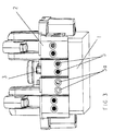
- Fig. 1 shows a schematic representation of a universal switch with a lower base block 1, an upper base block 2 and one movable selection element 3, which with the formation of an actuating element reaches through the upper base block, auxiliary rockers 4, whose actuating elements are arranged on the upper base block 2 are, and switching and contact chambers 7, these in turn in four Switching and contact chambers 7a-d are structured.
- auxiliary rockers 4 whose actuating elements are arranged on the upper base block 2 are, and switching and contact chambers 7, these in turn in four Switching and contact chambers 7a-d are structured.
- switching and contact elements 8a and 8b of the external auxiliary rockers shown in the switching and contact chambers 7a and 7d.
- the selection element 3 is designed as a movable sliding element, which on the front side, i.e. laterally on the input side of the lower base block between lower base block 1 and upper base block 2 is movable parallel to the end face, while it is moving the input openings 5 depending on the selection of those to be realized Circuit variant opens or closes. Only the movement aid the selection element 3 is visible here and protrudes through a groove in the upper base block 2 through. The selection element is parallel to the outer edge 9 within this groove in the upper base block 2 movable.
- the lower base block 1 and the front eight inputs 5 are provided in the upper base block 2, the upper base block 2 on the input side complementary to the lower base block 1 Must have input openings 5 if they are laterally overlap at their end faces.
- the selection element 3 gives all the input openings 5 in the lower one Base block 1 free.
- the selection element 3 shows a universal switchgear with a lower base block 1, an upper base block 2 and a movable selection element 3 in the manner of a sliding element, the selection of the circuit variant serving selection element 3 the upper base block 2 reaches through. On this protrude from the upper base block 2 Handle element, the selection element 3 along its path of movement be performed. Again, there are eight entrance openings on the input side 5 provided. By positioning the selection element 3 above the third lower entrance opening counting from left to right the inputs 5a, i.e. the lower inputs 5E2 and 5E3 open. All other upper and lower entrances are closed.
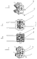
- Fig. 4 shows an example of the figures Fig. 4a to Fig. 4d, the Circuit variant series switch is shown.
- Figure 4a becomes an upper base block snapped onto a lower base block 1 2 shown.
- the movable selection element 3 is located in right position within its path of movement 10.
- the input opening 5E3 is connected.
- Figure 4b shows a lower base block 1 in plan view with the input and output assigned to the circuit variant series connection Exits.
- the figure Fig. 4c shows a top view Base block 2 with selection element 3 set in the right position, as well as inputs and outputs assigned according to the circuit variant.
- Figure 4d shows the universal rear derailleur on the output side. To implement the circuit variants, be connected in series the outputs 6A2 and 6A6 occupied.
- Figure 4b clearly shows the switching and contact elements 8a, 8b of the divided auxiliary rockers.
- Numeral 11 shows the auxiliary function illuminated, created within the series connection.
Landscapes
- Engineering & Computer Science (AREA)
- Manufacturing & Machinery (AREA)
- Brushes (AREA)
- Electrical Discharge Machining, Electrochemical Machining, And Combined Machining (AREA)
- Discharge Heating (AREA)
- Push-Button Switches (AREA)
- Switch Cases, Indication, And Locking (AREA)
- Switches With Compound Operations (AREA)
- Vehicle Body Suspensions (AREA)
- Devices For Use In Laboratory Experiments (AREA)
- Relay Circuits (AREA)
- Developing Agents For Electrophotography (AREA)
- Motorcycle And Bicycle Frame (AREA)
- Forging (AREA)
- Control Of Throttle Valves Provided In The Intake System Or In The Exhaust System (AREA)
- Lock And Its Accessories (AREA)
- Valve Device For Special Equipments (AREA)
- Power Conversion In General (AREA)
Description
- Fig. 1
- zeigt in schematischer Darstellung ein Universalschaltwerk mit allen angelegten Schaltungsvarianten, bestehend aus einem oberen Sockelblock, einem unteren Sockelblock und Schalt- und Kontaktkammern;
- Fig. 2
- zeigt ein Universalschaltwerk mit Auswahlelement, wobei alle Eingangsöffnungen geöffnet sind;
- Fig. 3
- zeigt ein Universalschaltwerk mit Auswahlelement, wobei zwei Eingänge geöffnet sind und alle weiteren Eingänge verschlossen sind;
- Fig. 4
- zeigt die Schaltungsvariante Serienschalter beispielhaft.
Claims (11)
- Elektrisches Universalschaltwerk als Schalter oder Taster, mit einem in einem Gehäuse angeordneten oberen Sockelblock (2), einem unteren Sockelblock (1), in welchem Schaltkammern, Kontaktkammern und Eingangs- und Ausgangsöffnungen angeordnet sind, welche Schalt-und Kontaktelemente zur Bildung von elektrisch leitenden Strompfaden aufnehmen und einer Hilfswippe (4),
wobei
im unteren Sockelblock (1) innerhalb der Schalt- und Kontaktkammern (7) die elektrisch leitenden Strompfade für die Schaltungsvarianten Aus einpolig, Aus einpolig-beleuchtet, Aus zweipolig, Kontroll-Aus einpolig, Aus zweipolig, Aus zweipolig - beleuchtet in zwei Schaltvarianten, Wechsel, Wechsel-beleuchtet, Kontroll-Wechsel, Doppel-Wechsel, Doppel-Wechsel-beleuchtet, Serie, Serie-beleuchtet und Taster angelegt und geschaltet sind,wobei jeder Schaltungsvariante definierte Ein- und Ausgänge (5,6) im unteren Sockelblock (1) und im oberen Sockelblock (2) zugewiesen sind, dadurch gekennzeichnet, daßüber Auswahlelemente (3) die zu realisierende Schaltungsvariante definiert und ausgewählt wird,wobei die Schalt-und Kontaktelemente (8a,8b) zur Realisierung des Strompfades eine geteilt ausgebildete Hilfswippe (4) aufweisen. - Elektrisches Universalschaltwerk nach Anspruch 1,
dadurch gekennzeichnet,
daß die Auswahlelemente (3) in Form eines beweglichen Elementes ausgebildet ist, welches die Eingangs- und Ausgangsöffnungen (5,6) des unteren Sockelblockes (1) und des oberen Sockelblockes (2) öffnet und verschließt. - Elektrisches Universalschaltwerk nach Anspruch 1 und 2,
dadurch gekennzeichnet,
daß mit Auswahl und Definition der zu realisierenden Schaltungsvariante durch die beweglichen Auswahlelement (3) gleichzeitig die der gewählten Schaltungsvariante zugewiesenen Eingangsöffnungen (5) und Ausgangsöffnungen (6) im unteren Sockelblock (1) und im oberen Sockelblock (2) geöffnet und alle weiteren Eingangsöffnungen (5) und Ausgangsöffnungen (6) geschlossen werden. - Elektrisches Universalschaltwerk nach Anspruch 1 bis 3,
dadurch gekennzeichnet,
daß die die Schaltungsvarianten auswählenden beweglichen Auswahlelemente (3) zwischen unterem Sockelblock (1) und oberem Sockelblock (2) angeordnet sind und Öffnungen aufweisen, wobei die Auswahlelemente (3) in ihrer Lage hinsichtlich der Eingangs- und/oder Ausgangsöffnungen (5,6) im unteren Sockelblock (1) und im oberen Sockelblock (2) so bewegbar sind, daß sie ausgewählte Eingangs- und/oder Ausgangsöffnungen (5,6) schließen oder freigeben. - Elektrisches Universalschaltwerk nach Anspruch 4,
dadurch gekennzeichnet,
daß die die Schaltvarianten auswählenden und zwischen oberem (1) und unterem Sockelblock (2) bewegbaren Auswahlelemente (3) gegenüber den Eingangs- und/oder Ausgangsöffnungen (5,6) als auch gegeneinander beweglich verschiebbar ausgebildet sind. - Elektrisches Universalschaltwerk nach Anspruch 1 bis 5,
dadurch gekennzeichnet,
daß die beweglichen Auswahlelemente (3) unabhängig voneinander und gegenüber den Eingangsöffnungen (5) und/oder Ausgangsöffnungen (6) im unteren (1) und oberen Sockelblock (2) zwischen Endlagen bewegbar sind, wobei feststehenden Bezugspunkten auf dem Bewegungsweg jeweils definierte Schaltungsvarianten zugewiesen sind. - Elektrisches Universalschaltwerk nach Anspruch 1 bis 6,
dadurch gekennzeichnet,
daß die beweglichen Auswahlelemente (3) den oberen (2) und/oder unteren Sockelblock (1) so durchgreifen, daß der Bewegungsweg extern von der Oberfläche des oberen Sockelblockes (2) aus einstellbar und veränderbar ist. - Elektrisches Universalschaltwerk nach einem der vorgenannten Ansprüche,
dadurch gekennzeichnet,
daß der obere Sockelblock (2) so ausgebildet ist, daß er wahlweise Schalt- und/oder Tastfunktionen realisieren kann. - Elektrisches Universalschaltwerk nach Anspruch 1 und 2,
dadurch gekennzeichnet,
daß die beweglichen Auswahlelemente (3) als U-förmige Gleitelemente mit mindestens zwei Führungen zur Kippstabilisierung ausgebildet sind. - Elektrisches Universalschaltwerk nach einem der vorgenannten Ansprüche,
dadurch gekennzeichnet,
daß die Hilfswippe (4) mindestens zweigeteilt ausgebildet ist und jedes der Hilfswippenteile (4a,4b) in einer separaten Schalt- und Kontaktkammer (7) angelegt ist. - Elektrisches Universalschaltwerk nach Anspruch 10
dadurch gekennzeichnet,
daß das Universalschaltwerk vier Schalt- und Kontaktkammern (7a,7b,7c,7d) aufweist, wobei die Hilfswippenteile (4a,4b) in den jeweils äußeren Schalt- und Kontaktkammern (7a,7d) angelegt sind.
Applications Claiming Priority (5)
| Application Number | Priority Date | Filing Date | Title |
|---|---|---|---|
| DE19654252 | 1996-12-23 | ||
| DE19654252 | 1996-12-23 | ||
| DE19750610 | 1997-11-14 | ||
| DE19750610A DE19750610C2 (de) | 1996-12-23 | 1997-11-14 | Elektrisches Universalschaltwerk |
| PCT/EP1997/007073 WO1998028761A1 (de) | 1996-12-23 | 1997-12-16 | Elektrisches universalschaltwerk |
Publications (2)
| Publication Number | Publication Date |
|---|---|
| EP0946955A1 EP0946955A1 (de) | 1999-10-06 |
| EP0946955B1 true EP0946955B1 (de) | 2000-06-14 |
Family
ID=26032768
Family Applications (1)
| Application Number | Title | Priority Date | Filing Date |
|---|---|---|---|
| EP97954410A Expired - Lifetime EP0946955B1 (de) | 1996-12-23 | 1997-12-16 | Elektrisches universalschaltwerk |
Country Status (11)
| Country | Link |
|---|---|
| EP (1) | EP0946955B1 (de) |
| AT (1) | ATE193959T1 (de) |
| CZ (1) | CZ298046B6 (de) |
| ES (1) | ES2149019T3 (de) |
| GR (1) | GR3034409T3 (de) |
| HR (1) | HRP970697B1 (de) |
| HU (1) | HUP0000545A3 (de) |
| NO (1) | NO317120B1 (de) |
| PL (1) | PL187356B1 (de) |
| PT (1) | PT946955E (de) |
| WO (1) | WO1998028761A1 (de) |
Families Citing this family (1)
| Publication number | Priority date | Publication date | Assignee | Title |
|---|---|---|---|---|
| DE102010053291B4 (de) * | 2010-12-02 | 2013-07-18 | Abb Ag | Installationsschaltgerät mit einer Federzugklemme |
Family Cites Families (1)
| Publication number | Priority date | Publication date | Assignee | Title |
|---|---|---|---|---|
| DE4135208C3 (de) * | 1991-10-25 | 1999-04-08 | Giersiepen Gira Gmbh | Elektrisches Installationsgerät |
-
1997
- 1997-12-16 HU HU0000545A patent/HUP0000545A3/hu unknown
- 1997-12-16 ES ES97954410T patent/ES2149019T3/es not_active Expired - Lifetime
- 1997-12-16 WO PCT/EP1997/007073 patent/WO1998028761A1/de active IP Right Grant
- 1997-12-16 PL PL97334056A patent/PL187356B1/pl not_active IP Right Cessation
- 1997-12-16 CZ CZ0157399A patent/CZ298046B6/cs not_active IP Right Cessation
- 1997-12-16 EP EP97954410A patent/EP0946955B1/de not_active Expired - Lifetime
- 1997-12-16 PT PT97954410T patent/PT946955E/pt unknown
- 1997-12-16 AT AT97954410T patent/ATE193959T1/de not_active IP Right Cessation
- 1997-12-22 HR HR970697A patent/HRP970697B1/xx not_active IP Right Cessation
-
1999
- 1999-06-22 NO NO19993097A patent/NO317120B1/no unknown
-
2000
- 2000-09-14 GR GR20000402097T patent/GR3034409T3/el not_active IP Right Cessation
Also Published As
| Publication number | Publication date |
|---|---|
| PL334056A1 (en) | 2000-01-31 |
| CZ157399A3 (cs) | 1999-10-13 |
| CZ298046B6 (cs) | 2007-06-06 |
| WO1998028761A1 (de) | 1998-07-02 |
| PL187356B1 (pl) | 2004-06-30 |
| HRP970697B1 (en) | 2001-08-31 |
| GR3034409T3 (en) | 2000-12-29 |
| HRP970697A2 (en) | 2001-02-28 |
| NO993097D0 (no) | 1999-06-22 |
| NO317120B1 (no) | 2004-08-16 |
| HUP0000545A3 (en) | 2000-07-28 |
| HUP0000545A2 (hu) | 2000-06-28 |
| PT946955E (pt) | 2000-09-29 |
| NO993097L (no) | 1999-08-17 |
| EP0946955A1 (de) | 1999-10-06 |
| ATE193959T1 (de) | 2000-06-15 |
| ES2149019T3 (es) | 2000-10-16 |
Similar Documents
| Publication | Publication Date | Title |
|---|---|---|
| EP0650637B1 (de) | Stufenschalter | |
| DE19743865C1 (de) | Stufenschalter | |
| DE4412294A1 (de) | Sicherheitsabschaltung | |
| DE4237165C1 (de) | Einpoliger Stufenschalter mit linearer Kontaktbetätigung für einen Stufentransformator | |
| DE2951327C2 (de) | Schaltvorrichtung | |
| EP0946955B1 (de) | Elektrisches universalschaltwerk | |
| DE3249953C2 (de) | Elektrischer Mehrpositions-Schalter | |
| DE7426189U (de) | HilfGeschalter-Anbauteil für Leitungsschutzschalter | |
| CH623681A5 (de) | ||
| DE19750610C2 (de) | Elektrisches Universalschaltwerk | |
| EP0678885A1 (de) | Elektrischer Tastschalter | |
| DE3048371A1 (de) | Zweirichtungsschalter | |
| DE2426054A1 (de) | Vorrichtung zur betaetigung von drei unterbrechern mit hilfe von zwei druckknoepfen | |
| DE3334671A1 (de) | Mehrzweckschalter fuer videokameras | |
| DE3000748C2 (de) | Stufenschalter für einen dreiphasigen Transformator mit sternförmig zusammengeschalteten Vakuumschaltern | |
| EP0825629B1 (de) | Niederspannungsschalgerät | |
| EP0820082A2 (de) | Elektrisches Schaltgerät | |
| DE2855222C2 (de) | Elektrischer Drucktastenschalter | |
| DE2359628C3 (de) | Wender zum Umschalten der Fein- oder Grobstufenwicklung eines mit einem Stufenschalter ausgerüsteten Transformators | |
| DE2403762C3 (de) | Wender zum Umschalten der Fein- oder Grobstufenwicklung von mit einem Stufenschalter ausgerüsteten Transformatoren | |
| DE3145954A1 (de) | Elektrischer kippschalter | |
| DE102010024612B4 (de) | Stufenschalter | |
| DE2539610C3 (de) | Schalteranordnung | |
| DE2949463C3 (de) | Schaltanordnung zur Querspannungsregelung eines dreiphasigen Stufentransformators | |
| EP0956575A1 (de) | Leistungsschalter zum schalten elektrischer stromkreise |
Legal Events
| Date | Code | Title | Description |
|---|---|---|---|
| PUAI | Public reference made under article 153(3) epc to a published international application that has entered the european phase |
Free format text: ORIGINAL CODE: 0009012 |
|
| 17P | Request for examination filed |
Effective date: 19990623 |
|
| AK | Designated contracting states |
Kind code of ref document: A1 Designated state(s): AT BE CH DE DK ES FI FR GR IT LI LU NL PT SE |
|
| GRAG | Despatch of communication of intention to grant |
Free format text: ORIGINAL CODE: EPIDOS AGRA |
|
| GRAG | Despatch of communication of intention to grant |
Free format text: ORIGINAL CODE: EPIDOS AGRA |
|
| GRAH | Despatch of communication of intention to grant a patent |
Free format text: ORIGINAL CODE: EPIDOS IGRA |
|
| 17Q | First examination report despatched |
Effective date: 19991108 |
|
| GRAH | Despatch of communication of intention to grant a patent |
Free format text: ORIGINAL CODE: EPIDOS IGRA |
|
| GRAA | (expected) grant |
Free format text: ORIGINAL CODE: 0009210 |
|
| AK | Designated contracting states |
Kind code of ref document: B1 Designated state(s): AT BE CH DE DK ES FI FR GR IT LI LU NL PT SE |
|
| REF | Corresponds to: |
Ref document number: 193959 Country of ref document: AT Date of ref document: 20000615 Kind code of ref document: T |
|
| REG | Reference to a national code |
Ref country code: CH Ref legal event code: NV Representative=s name: SCHMAUDER & PARTNER AG PATENTANWALTSBUERO Ref country code: CH Ref legal event code: EP |
|
| REF | Corresponds to: |
Ref document number: 59701900 Country of ref document: DE Date of ref document: 20000720 |
|
| REG | Reference to a national code |
Ref country code: DK Ref legal event code: T3 |
|
| ET | Fr: translation filed | ||
| ITF | It: translation for a ep patent filed |
Owner name: STUDIO JAUMANN P. & C. S.N.C. |
|
| REG | Reference to a national code |
Ref country code: PT Ref legal event code: SC4A Free format text: AVAILABILITY OF NATIONAL TRANSLATION Effective date: 20000627 |
|
| REG | Reference to a national code |
Ref country code: ES Ref legal event code: FG2A Ref document number: 2149019 Country of ref document: ES Kind code of ref document: T3 |
|
| PLBE | No opposition filed within time limit |
Free format text: ORIGINAL CODE: 0009261 |
|
| STAA | Information on the status of an ep patent application or granted ep patent |
Free format text: STATUS: NO OPPOSITION FILED WITHIN TIME LIMIT |
|
| 26N | No opposition filed | ||
| PGFP | Annual fee paid to national office [announced via postgrant information from national office to epo] |
Ref country code: SE Payment date: 20011221 Year of fee payment: 5 |
|
| PGFP | Annual fee paid to national office [announced via postgrant information from national office to epo] |
Ref country code: DK Payment date: 20011227 Year of fee payment: 5 Ref country code: NL Payment date: 20011227 Year of fee payment: 5 |
|
| PGFP | Annual fee paid to national office [announced via postgrant information from national office to epo] |
Ref country code: LU Payment date: 20020103 Year of fee payment: 5 |
|
| PGFP | Annual fee paid to national office [announced via postgrant information from national office to epo] |
Ref country code: BE Payment date: 20020111 Year of fee payment: 5 |
|
| PG25 | Lapsed in a contracting state [announced via postgrant information from national office to epo] |
Ref country code: LU Free format text: LAPSE BECAUSE OF NON-PAYMENT OF DUE FEES Effective date: 20021216 |
|
| PG25 | Lapsed in a contracting state [announced via postgrant information from national office to epo] |
Ref country code: SE Free format text: LAPSE BECAUSE OF NON-PAYMENT OF DUE FEES Effective date: 20021217 |
|
| PG25 | Lapsed in a contracting state [announced via postgrant information from national office to epo] |
Ref country code: BE Free format text: LAPSE BECAUSE OF NON-PAYMENT OF DUE FEES Effective date: 20021231 |
|
| PG25 | Lapsed in a contracting state [announced via postgrant information from national office to epo] |
Ref country code: DK Free format text: LAPSE BECAUSE OF NON-PAYMENT OF DUE FEES Effective date: 20030131 |
|
| BERE | Be: lapsed |
Owner name: *N & L ELEKTROTECHNIK G.M.B.H. Effective date: 20021231 |
|
| PG25 | Lapsed in a contracting state [announced via postgrant information from national office to epo] |
Ref country code: NL Free format text: LAPSE BECAUSE OF NON-PAYMENT OF DUE FEES Effective date: 20030701 |
|
| EUG | Se: european patent has lapsed | ||
| REG | Reference to a national code |
Ref country code: DK Ref legal event code: EBP |
|
| NLV4 | Nl: lapsed or anulled due to non-payment of the annual fee |
Effective date: 20030701 |
|
| PG25 | Lapsed in a contracting state [announced via postgrant information from national office to epo] |
Ref country code: IT Free format text: LAPSE BECAUSE OF NON-PAYMENT OF DUE FEES;WARNING: LAPSES OF ITALIAN PATENTS WITH EFFECTIVE DATE BEFORE 2007 MAY HAVE OCCURRED AT ANY TIME BEFORE 2007. THE CORRECT EFFECTIVE DATE MAY BE DIFFERENT FROM THE ONE RECORDED. Effective date: 20051216 |
|
| PGFP | Annual fee paid to national office [announced via postgrant information from national office to epo] |
Ref country code: PT Payment date: 20061215 Year of fee payment: 10 |
|
| PGFP | Annual fee paid to national office [announced via postgrant information from national office to epo] |
Ref country code: ES Payment date: 20061219 Year of fee payment: 10 |
|
| PGFP | Annual fee paid to national office [announced via postgrant information from national office to epo] |
Ref country code: CH Payment date: 20061220 Year of fee payment: 10 |
|
| PGFP | Annual fee paid to national office [announced via postgrant information from national office to epo] |
Ref country code: GR Payment date: 20061221 Year of fee payment: 10 Ref country code: FI Payment date: 20061221 Year of fee payment: 10 |
|
| REG | Reference to a national code |
Ref country code: PT Ref legal event code: MM4A Free format text: LAPSE DUE TO NON-PAYMENT OF FEES Effective date: 20080616 |
|
| PG25 | Lapsed in a contracting state [announced via postgrant information from national office to epo] |
Ref country code: FI Free format text: LAPSE BECAUSE OF NON-PAYMENT OF DUE FEES Effective date: 20071216 |
|
| REG | Reference to a national code |
Ref country code: CH Ref legal event code: PL |
|
| PG25 | Lapsed in a contracting state [announced via postgrant information from national office to epo] |
Ref country code: PT Free format text: LAPSE BECAUSE OF NON-PAYMENT OF DUE FEES Effective date: 20080616 |
|
| PG25 | Lapsed in a contracting state [announced via postgrant information from national office to epo] |
Ref country code: LI Free format text: LAPSE BECAUSE OF NON-PAYMENT OF DUE FEES Effective date: 20071231 Ref country code: CH Free format text: LAPSE BECAUSE OF NON-PAYMENT OF DUE FEES Effective date: 20071231 |
|
| PGFP | Annual fee paid to national office [announced via postgrant information from national office to epo] |
Ref country code: AT Payment date: 20081218 Year of fee payment: 12 |
|
| REG | Reference to a national code |
Ref country code: ES Ref legal event code: FD2A Effective date: 20071217 |
|
| PG25 | Lapsed in a contracting state [announced via postgrant information from national office to epo] |
Ref country code: ES Free format text: LAPSE BECAUSE OF NON-PAYMENT OF DUE FEES Effective date: 20071217 |
|
| PG25 | Lapsed in a contracting state [announced via postgrant information from national office to epo] |
Ref country code: GR Free format text: LAPSE BECAUSE OF NON-PAYMENT OF DUE FEES Effective date: 20080702 |
|
| PG25 | Lapsed in a contracting state [announced via postgrant information from national office to epo] |
Ref country code: AT Free format text: LAPSE BECAUSE OF NON-PAYMENT OF DUE FEES Effective date: 20091216 |
|
| REG | Reference to a national code |
Ref country code: FR Ref legal event code: PLFP Year of fee payment: 19 |
|
| REG | Reference to a national code |
Ref country code: FR Ref legal event code: PLFP Year of fee payment: 20 |
|
| PGFP | Annual fee paid to national office [announced via postgrant information from national office to epo] |
Ref country code: FR Payment date: 20161221 Year of fee payment: 20 |
|
| PGFP | Annual fee paid to national office [announced via postgrant information from national office to epo] |
Ref country code: DE Payment date: 20161229 Year of fee payment: 20 |
|
| REG | Reference to a national code |
Ref country code: DE Ref legal event code: R071 Ref document number: 59701900 Country of ref document: DE |