EP0946388B1 - Steuerungssystem für ein getriebe und getriebe mit einem solchen system - Google Patents
Steuerungssystem für ein getriebe und getriebe mit einem solchen system Download PDFInfo
- Publication number
- EP0946388B1 EP0946388B1 EP97951398A EP97951398A EP0946388B1 EP 0946388 B1 EP0946388 B1 EP 0946388B1 EP 97951398 A EP97951398 A EP 97951398A EP 97951398 A EP97951398 A EP 97951398A EP 0946388 B1 EP0946388 B1 EP 0946388B1
- Authority
- EP
- European Patent Office
- Prior art keywords
- valve
- fluid
- engine
- control system
- control unit
- Prior art date
- Legal status (The legal status is an assumption and is not a legal conclusion. Google has not performed a legal analysis and makes no representation as to the accuracy of the status listed.)
- Expired - Lifetime
Links
- 230000005540 biological transmission Effects 0.000 title claims description 38
- 239000012530 fluid Substances 0.000 claims description 44
- 230000007246 mechanism Effects 0.000 claims description 20
- 230000008878 coupling Effects 0.000 claims description 18
- 238000010168 coupling process Methods 0.000 claims description 18
- 238000005859 coupling reaction Methods 0.000 claims description 18
- 238000004891 communication Methods 0.000 claims description 8
- 238000012544 monitoring process Methods 0.000 claims description 5
- 230000000737 periodic effect Effects 0.000 claims description 4
- 230000007935 neutral effect Effects 0.000 description 3
- 239000000446 fuel Substances 0.000 description 2
- 230000008901 benefit Effects 0.000 description 1
- 239000004020 conductor Substances 0.000 description 1
- 231100001261 hazardous Toxicity 0.000 description 1
- 238000000034 method Methods 0.000 description 1
- 230000008569 process Effects 0.000 description 1
- 230000001141 propulsive effect Effects 0.000 description 1
- 230000009467 reduction Effects 0.000 description 1
- 230000004044 response Effects 0.000 description 1
- 238000011144 upstream manufacturing Methods 0.000 description 1
- XLYOFNOQVPJJNP-UHFFFAOYSA-N water Substances O XLYOFNOQVPJJNP-UHFFFAOYSA-N 0.000 description 1
Images


Classifications
-
- B—PERFORMING OPERATIONS; TRANSPORTING
- B63—SHIPS OR OTHER WATERBORNE VESSELS; RELATED EQUIPMENT
- B63H—MARINE PROPULSION OR STEERING
- B63H23/00—Transmitting power from propulsion power plant to propulsive elements
- B63H23/02—Transmitting power from propulsion power plant to propulsive elements with mechanical gearing
- B63H23/08—Transmitting power from propulsion power plant to propulsive elements with mechanical gearing with provision for reversing drive
-
- B—PERFORMING OPERATIONS; TRANSPORTING
- B63—SHIPS OR OTHER WATERBORNE VESSELS; RELATED EQUIPMENT
- B63H—MARINE PROPULSION OR STEERING
- B63H23/00—Transmitting power from propulsion power plant to propulsive elements
- B63H23/30—Transmitting power from propulsion power plant to propulsive elements characterised by use of clutches
-
- F—MECHANICAL ENGINEERING; LIGHTING; HEATING; WEAPONS; BLASTING
- F16—ENGINEERING ELEMENTS AND UNITS; GENERAL MEASURES FOR PRODUCING AND MAINTAINING EFFECTIVE FUNCTIONING OF MACHINES OR INSTALLATIONS; THERMAL INSULATION IN GENERAL
- F16D—COUPLINGS FOR TRANSMITTING ROTATION; CLUTCHES; BRAKES
- F16D48/00—External control of clutches
- F16D48/06—Control by electric or electronic means, e.g. of fluid pressure
- F16D48/062—Control by electric or electronic means, e.g. of fluid pressure of a clutch system with a plurality of fluid actuated clutches
-
- F—MECHANICAL ENGINEERING; LIGHTING; HEATING; WEAPONS; BLASTING
- F16—ENGINEERING ELEMENTS AND UNITS; GENERAL MEASURES FOR PRODUCING AND MAINTAINING EFFECTIVE FUNCTIONING OF MACHINES OR INSTALLATIONS; THERMAL INSULATION IN GENERAL
- F16D—COUPLINGS FOR TRANSMITTING ROTATION; CLUTCHES; BRAKES
- F16D48/00—External control of clutches
- F16D48/06—Control by electric or electronic means, e.g. of fluid pressure
- F16D48/066—Control of fluid pressure, e.g. using an accumulator
-
- F—MECHANICAL ENGINEERING; LIGHTING; HEATING; WEAPONS; BLASTING
- F16—ENGINEERING ELEMENTS AND UNITS; GENERAL MEASURES FOR PRODUCING AND MAINTAINING EFFECTIVE FUNCTIONING OF MACHINES OR INSTALLATIONS; THERMAL INSULATION IN GENERAL
- F16D—COUPLINGS FOR TRANSMITTING ROTATION; CLUTCHES; BRAKES
- F16D2500/00—External control of clutches by electric or electronic means
- F16D2500/10—System to be controlled
- F16D2500/102—Actuator
- F16D2500/1026—Hydraulic
- F16D2500/1027—Details about the hydraulic valves
-
- F—MECHANICAL ENGINEERING; LIGHTING; HEATING; WEAPONS; BLASTING
- F16—ENGINEERING ELEMENTS AND UNITS; GENERAL MEASURES FOR PRODUCING AND MAINTAINING EFFECTIVE FUNCTIONING OF MACHINES OR INSTALLATIONS; THERMAL INSULATION IN GENERAL
- F16D—COUPLINGS FOR TRANSMITTING ROTATION; CLUTCHES; BRAKES
- F16D2500/00—External control of clutches by electric or electronic means
- F16D2500/10—System to be controlled
- F16D2500/11—Application
- F16D2500/1105—Marine applications
-
- F—MECHANICAL ENGINEERING; LIGHTING; HEATING; WEAPONS; BLASTING
- F16—ENGINEERING ELEMENTS AND UNITS; GENERAL MEASURES FOR PRODUCING AND MAINTAINING EFFECTIVE FUNCTIONING OF MACHINES OR INSTALLATIONS; THERMAL INSULATION IN GENERAL
- F16D—COUPLINGS FOR TRANSMITTING ROTATION; CLUTCHES; BRAKES
- F16D2500/00—External control of clutches by electric or electronic means
- F16D2500/30—Signal inputs
- F16D2500/314—Signal inputs from the user
- F16D2500/3146—Signal inputs from the user input from levers
-
- F—MECHANICAL ENGINEERING; LIGHTING; HEATING; WEAPONS; BLASTING
- F16—ENGINEERING ELEMENTS AND UNITS; GENERAL MEASURES FOR PRODUCING AND MAINTAINING EFFECTIVE FUNCTIONING OF MACHINES OR INSTALLATIONS; THERMAL INSULATION IN GENERAL
- F16D—COUPLINGS FOR TRANSMITTING ROTATION; CLUTCHES; BRAKES
- F16D2500/00—External control of clutches by electric or electronic means
- F16D2500/30—Signal inputs
- F16D2500/316—Other signal inputs not covered by the groups above
- F16D2500/3166—Detection of an elapsed period of time
-
- F—MECHANICAL ENGINEERING; LIGHTING; HEATING; WEAPONS; BLASTING
- F16—ENGINEERING ELEMENTS AND UNITS; GENERAL MEASURES FOR PRODUCING AND MAINTAINING EFFECTIVE FUNCTIONING OF MACHINES OR INSTALLATIONS; THERMAL INSULATION IN GENERAL
- F16D—COUPLINGS FOR TRANSMITTING ROTATION; CLUTCHES; BRAKES
- F16D2500/00—External control of clutches by electric or electronic means
- F16D2500/50—Problem to be solved by the control system
- F16D2500/51—Relating safety
- F16D2500/5108—Failure diagnosis
- F16D2500/5112—Using signals from redundant sensors
-
- F—MECHANICAL ENGINEERING; LIGHTING; HEATING; WEAPONS; BLASTING
- F16—ENGINEERING ELEMENTS AND UNITS; GENERAL MEASURES FOR PRODUCING AND MAINTAINING EFFECTIVE FUNCTIONING OF MACHINES OR INSTALLATIONS; THERMAL INSULATION IN GENERAL
- F16D—COUPLINGS FOR TRANSMITTING ROTATION; CLUTCHES; BRAKES
- F16D2500/00—External control of clutches by electric or electronic means
- F16D2500/70—Details about the implementation of the control system
- F16D2500/704—Output parameters from the control unit; Target parameters to be controlled
- F16D2500/70452—Engine parameters
- F16D2500/70462—Opening of the throttle valve
-
- F—MECHANICAL ENGINEERING; LIGHTING; HEATING; WEAPONS; BLASTING
- F16—ENGINEERING ELEMENTS AND UNITS; GENERAL MEASURES FOR PRODUCING AND MAINTAINING EFFECTIVE FUNCTIONING OF MACHINES OR INSTALLATIONS; THERMAL INSULATION IN GENERAL
- F16D—COUPLINGS FOR TRANSMITTING ROTATION; CLUTCHES; BRAKES
- F16D2500/00—External control of clutches by electric or electronic means
- F16D2500/70—Details about the implementation of the control system
- F16D2500/71—Actions
- F16D2500/7101—Driver alarm
-
- F—MECHANICAL ENGINEERING; LIGHTING; HEATING; WEAPONS; BLASTING
- F16—ENGINEERING ELEMENTS AND UNITS; GENERAL MEASURES FOR PRODUCING AND MAINTAINING EFFECTIVE FUNCTIONING OF MACHINES OR INSTALLATIONS; THERMAL INSULATION IN GENERAL
- F16D—COUPLINGS FOR TRANSMITTING ROTATION; CLUTCHES; BRAKES
- F16D2500/00—External control of clutches by electric or electronic means
- F16D2500/70—Details about the implementation of the control system
- F16D2500/71—Actions
- F16D2500/7107—Others
- F16D2500/7109—Pulsed signal; Generating or processing pulsed signals; PWM, width modulation, frequency or amplitude modulation
-
- Y—GENERAL TAGGING OF NEW TECHNOLOGICAL DEVELOPMENTS; GENERAL TAGGING OF CROSS-SECTIONAL TECHNOLOGIES SPANNING OVER SEVERAL SECTIONS OF THE IPC; TECHNICAL SUBJECTS COVERED BY FORMER USPC CROSS-REFERENCE ART COLLECTIONS [XRACs] AND DIGESTS
- Y10—TECHNICAL SUBJECTS COVERED BY FORMER USPC
- Y10S—TECHNICAL SUBJECTS COVERED BY FORMER USPC CROSS-REFERENCE ART COLLECTIONS [XRACs] AND DIGESTS
- Y10S477/00—Interrelated power delivery controls, including engine control
- Y10S477/906—Means detecting or ameliorating the effects of malfunction or potential malfunction
Definitions
- the present invention relates to a control system for a transmission, and more particularly to a control system fitted to a transmission for marine application in which the output drive shaft is arranged to drive a propeller unit.
- Marine propulsion systems are typically constructed with an engine driving a propeller by means of an intermediate transmission.
- the transmission may also include one or more coupling means in the form of a clutch that allows for the engagement and disengagement of the transmission with the propeller drive shaft.
- Such a transmission can be arranged to provide both forward and reverse operation of the propeller drive shaft.
- the engine-driven input shaft of the transmission is permanently connected, by a conical gear coupling, to a pair of opposed conical gears.
- Each of the gears is also rotatably supported on the transmission output drive shaft so that the opposed conical gears can rotate without being engaged with the transmission output shaft.
- each conical gear is arranged with its own fluid clutch. The clutches are engaged by supplying fluid pressure to them. Engagement of a clutch will thus cause either forward or reverse rotation of said transmission output shaft.
- the present invention reduces or overcomes the aforementioned vibrational problems by the provision of an appropriate control arrangement for the transmission system.
- the present invention provides a control system for an engine transmission where the transmission is provided with a coupling mechanism for engaging and disengaging the transmission.
- the control system has at least one valve movable between first and second positions for controlling engagement and disengagement of the coupling mechanism of the transmission.
- An automatic control unit is connected to the valve, and includes an intermittent signal supply trigger for supplying an intermittent pulsed signal to the valve. The intermittent pulsed signal causes intermittent movement of the valve between its first and said second positions.
- the invention further provides transmission for a boat engine.
- the transmission includes a power input, an output drive shaft, engageable to the input shaft; and a coupling mechanism for engaging and disengaging the input and output shafts.
- a control system is provided which includes first and second fluid valves in communication with the coupling mechanism. Each valve is movable between first and second positions for controlling engagement and disengagement of the coupling mechanism.
- An automatic control unit connected to said first and second fluid valves, is also provided.
- the control unit includes an intermittent signal supply trigger for supplying an intermittent pulsed signal to the first and second fluid valves. This intermittent signal causes the valves to move intermittently between the first and second positions.
- the invention includes a control system having a valve that controls engagement and disengagement of the clutch of a transmission.
- the valve has two positions. In one of the valve's positions, the valve supplies the clutch with pressure fluid, thereby actuating the clutch. In the other position, the valve cuts off fluid to the clutch, thereby de-actuating the clutch.
- the automatic control unit may be in communication with an engine throttle control unit and may receive input signals from the throttle control unit corresponding to the throttle position, for the purpose of varying pulse duration and the like.
- the control system preferably utilizes at least one electrically operable fluid valve, and more preferably utilizes two valves, one for forward drive, and the other for reverse drive. In the case where two valves are utilized, the automatic control unit supplies the intermittent pulsed signal to only one of the valves at a given time.
- the control system may preferably be provided with several safety features.
- the valves may be arranged so that when both of the valves are in their respective non-actuated positions (e.g., when there is a complete electrical failure), only one of the valves is in a position to supply fluid to its clutch.
- the system may more preferably be provided with a fault detector, an engine stopping mechanism, and/or a warning indicator. When the fault detector detects a fault has occurred in the one or more valves, a control circuit may light a warning light, or may activate an engine cutoff device to stop the engine from running during the fault.
- the typical transmission device depicted in Figure 1 will be used to help understanding of the type of operation to which the control system of the application is directed.
- the transmission device shown in Figure 1 is one which is applied to a boat propeller drive and allows engagement of both forward and reverse drive.
- the transmission has an input shaft 1 driven by a power source of some type (not shown), and an output shaft 2 connected suitably to a propeller (not shown) or other propulsive means.
- a first conical gear 5 is fixedly attached to the input drive shaft 1 and is in permanent engagement with a pair of opposed conical gears 6 and 7. As will be evident, rotation of gear 5 in one direction will cause gears 6 and 7 to rotate in opposite directions to one another around the output shaft 2. Conical gear 6, in this case, will provide drive to the propeller for moving the boat in a rearward, direction and conical gear 7 will provide drive in the forward direction.
- Each of the gears 6 and 7 is freely rotatably mounted with respect to the output shaft 2 until engaged therewith by means of a coupling device; the coupling device shown here consists of two multi-plate fluid clutches 3 and 4. Each of clutches 3 and 4 acts individually so as to cause engagement (or disengagement) of one of the conical gears 6 and 7 with the output shaft 2.
- valve 9 fluid from a pump (not shown) will enter through passageway 8 into rotational valve 9. Rotation of the valve 9 in a clockwise direction will cause fluid pressure to be supplied to the upper clutch 3, and rotation of the valve 9 in a counter-clockwise direction will cause fluid pressure to be supplied to the lower clutch 4. Fluid communication between the valve 9 and the clutches 3 and 4 is arranged such that only one clutch can be actuated at any one time.
- the valve and clutches communicate by means of internal passageways in the drive shaft 2 and surrounding bearing/fluid supply unit 10.
- the schematic representation in Figure 2 comprises two coupling devices 13 and 14 corresponding, for example, to clutches 3 and 4 in Figure 1.
- clutch 13 will cause the transmission to provide reverse drive and clutch 14 will produce forward drive.
- Clutch 13 receives an engagement or disengagement control input via line 16 from a valve 18, whilst clutch 14 receives such a control input via line 15 from a valve 17.
- the lines 15 and 16 may be hydraulic fluid lines which are supplied with pressurized fluid, by means of pump P through lines 19 and 20, when valves 17 and 18 are in a predetermined position.
- the upper part of the schematically represented circuit is thus a fluid control circuit.
- Valves 17 and 18 are constructed to adopt each at least two positions (and normally only two positions), referred to herein below as a first position and a second position. In one of the positions of valve 17, the clutch 14 will be disengaged, and in the other position the clutch 14 will be engaged. Valve 17 and 18 are constructed so that they may periodically alternate between the first and the second position within a short response time for a large number of cycles without failure. A preferred valve embodiment will be explained below.
- An automatic control unit 23 is connected to valves 17 and 18 via lines 21 and 22 respectively.
- Said lines may be electrical, pneumatic, or hydraulic, but in the preferred embodiment they are electrical connections. However it should be understood that other type of connections are possible, such as light filament connections or even contactless connections requiring a transmitting unit for example. What is important is that communication between the various elements at the end of the various lines can be established.
- Automatic control unit 23 comprises an intermittent signal trigger 24.
- Trigger 24 may be an integral part of the automatic control unit 23, such as by being part of its circuitry or it may be separated from the main body of the control unit.
- trigger 24 might be placed near each of the valves and be connected to the main body of the automatic control unit by means of an electrical conductor.
- the trigger 24 has the purpose of supply an intermittent pulsed signal to one of valves 17 or 18, when the boat is intended to move forward or backwards slowly, i.e., at low engine speeds, typically between 500 and 900 r.p.m. but also up to about 1200 r.p.m.
- the intermittent signal will be sent to either valve 17 or valve 18 so as to displace it periodically between its respective first and second positions. In this way, one of the clutches will be intermittently engaged and disengaged.
- FIG. 3 An example of the pulsed signal supplied by said trigger 24 is depicted in Figure 3.
- a square pulse of duration "x" is intermittently supplied from the trigger 24.
- the pulse duration may vary preferably has a duration of between 0.5 and 3.0 seconds.
- each of the pulses of the intermittent signal has the same duration "x”.
- the length "T” indicates the periodic time of the pulse from the start of one pulse to the start of the next. Typically "T" will be about 3.0 seconds when the pulse duration is about 0.5 seconds.
- the pulse duration "x" with respect to the engine speed. This could be accomplished, for example, b varying the pulse duration from a long pulse duration of about 3 seconds at engine speeds up to about 1,200 r.p.m., and gradually reducing the pulse duration down to about 0.5 seconds at engine tickover speed.
- the automatic control unit can be arranged to perform this function without manual intervention or adjustment.
- This manual setting will enable the control system not only to be tuned to any of a number of boats or vessels, but also to be adjusted to compensate for modified conditions of the same boat (such as when the boat is carrying a heavy load, for example).
- the magnitude of the intermittent pulse of the signal will be chosen in accordance with the requirements for operating the valve.
- An engine throttle lever 26 is accurately movable around pivot 28 within a casing 25.
- the control system is designed to operate in the "low to tickover" speed range of the engine.
- a control input is fed via line 27 to unit 23, indicating the throttle lever position.
- the control unit 23 will be present with a predetermined engine speed, normally below 1,200 r.p.m., at which it is desired to couple in the intermittent signal supply trigger 24 of the control system.
- the control system of the invention is not only applicable to transmissions having two clutches. It may be suitable, depending on the boat or vessel concerned, to have only a forward drive; in such a case, only one valve 17 for intermittent engagement and disengagement of forward drive would be required. Moreover, even where two clutches are present for forward and reverse drive, it may still be suitable to use the intermittent drive only on the forward drive clutch since the reverse drive is used relatively rarely. This would save cost of course.
- FIG. 4 depicts the valves 17 and 18 as applied to a hydraulic circuit.
- Each of the valves 17, 18 is a 3/2 valve (3-way, 2-position).
- the valves are suitably constructed as electrically-operated solenoid valves, whereby the intermittent signal supplied from the signal supply means will be an electrical signal.
- valve 17, 18 is shown in its non-actuated position, whereby biasing means such as springs 30 and 31 force the valves to assume a position in which fluid from pump P is transferred via line 21 through valve inlet C to valve outlet B and via line 15 to cause engagement of forward drive clutch 14.
- valve 18 is in a position which allows hydraulic fluid to flow to the DUMP (and to the reservoir) from connection B via connection C. In this way, only the forward drive clutch is engaged.
- control system has a default setting such that hydraulic fluid will only be supplied to one valve (valve 17). This enables the engagement of forward drive only without the requirement of electrical power, and will thus allow the boat to be drive forwards to the engine as a "get-me-home" safety feature in the event of electrical failure.
- forward drive is engaged.
- Reverse drive can be engaged by moving valve 17 to the right and valve 18 to the right (the directions being taken as depicted in Figure 4).
- Neutral drive is engaged by moving valve 17 to the right and leaving valve 18 as shown in Figure 4.
- the movement of the valves 17, 18 from the unactuated position ( Figure 4) to the right constitutes a movement of the valve between first and second position (or between second and first positions) in accordance with this invention.
- the control lines 21 and 22 are responsible for transmitting the signal which causes such movement.
- the intermittent signal supply trigger is deactivated such that a constant signal is supplied to either valve 17 or valve 18 to activate it into the required position.
- the constant signal is overridden by the intermittent pulsed signal instead.
- control system can be fitted or retrofitted to an existing transmission, such as a transmission described in the prior art of Figure 1, by arranging that the valves are able to intermittently block and allow passage of fluid in the supply line to a respective clutch.
- the main forward and reverse drive control would operate as normal, but the extra valves 17 and 18 added to the system would act on the fluid supply lines communicating from the already existing forward drive circuit.
- Such a retrofitted system could be arranged with the intermittently operated valves either in, or upstream of, the fluid supply control lines of the existing system.
- the control means used in the transmission of Figure 1 could be replaced by a control unit according to the present invention.
- control circuitry for producing the control system in accordance with any of the above embodiments will not be described in detail in this application, as such circuitry can be constructed in many conventional ways, using either hydraulic, electrical, or electronic elements for example.
- the intermittent actuation of the forward (or rear) clutch at low speed will cause the propeller to be intermittently driven and then not driven.
- the tickover speed of the engine is, for example, 600 r.p.m.
- the "effective" driven r.p.m. of the propeller can be reduced down to a much lower value (e.g. 200 r.p.m.) when the intermittent drive is engaged.
- the "effective" r.p.m. is the number of revolutions per minute taken over one complete periodic time period of the pulsed signal. This has the advantage that vibrations often do not have a chance to establish themselves at all due to the vibration source being removed intermittently.
- the boat or vessel will feel more comfortable, which will be particularly noticeable when the boat is driven with the intermittent drive engaged for long periods of time.
- the intermittent drive or "trolling" drive as it is known, to achieve a much smoother passage through the water despite it being intermittent in nature, this being due to the short pulse duration of approximately 0.5 to 3.0 seconds.
- the boat can achieve not only a smoother ride, but also a slower lowest speed due to the effective r.p.m. reduction. This will facilitate precise maneuvering of the boat in small spaces or tight passageways without constant engagement of forward and reversed drives to achieve a desired forward drift speed of the boat.
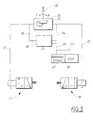
- FIG. 5 shows a further development of an electrical control circuit, in which a monitoring and warning/stop system is included in the electrical part of the valve circuit. Elements which have already been described have been given the same reference numeral. It will be noticed that although valves 17 and 18 have been depicted in a different orientation to that in Figure 4, the function of the valves is unchanged.
- Monitoring unit 32 is provided, and may be a resistance monitor, for example.
- the resistance monitor 32 is connected via electrical connections 33 and 34 with the control lines 21 and 22, respectively, which lead to the valves 17 and 18.
- the purpose of the resistance monitor 32 is to check whether there has been a failure in either (or both) of the lines 21 and 22, or in the valves 17 and 18, which has led to the valves 17 or 18 being left inoperative or partially inoperative. This can be done by providing a check on the resistance for example. The purpose of such control will be explained further below.
- warning signal unit 37 connected via line 35 to the monitoring unit 32.
- the warning signal unit 37 can issue a light or audible warning (or both) for example, so as to warn the boat driver that one (or both) of the valves 17 and/or 18 is inoperative.
- line 36 e.g., an electrical connection
- stop device 38 may be included, communicating with stop device 38 which will stop the engine if a particular error condition occurs, as explained below.
- stop device 38 For a diesel engine configuration, the engine might be stopped, by sending a current to the fuel supply stop magnet so as to cut off the fuel supply.
- the ignition would normally be cut when the engine is to be stopped.
- the system could be provided with a safety-override function so that, if necessary, the engine can be restarted as a further failsafe measure to avoid the boat being totally stranded when neutral was engaged during a particular manoeuvre when the electrical power to the valves 17 or 18 fails.
- the warning signal device 37 will warn the driver if either of the valves developed a fault while the engine is being operated and the boat is being driven. For example, if the boat was being driven in reverse and the forward drive valve 18 failed, the driver would be made aware of this fact and would realize that his normal possibilities of boat maneuvering were more limited, since the "get-me-home" function would have to be engaged. The stop function would not need to be actuated in such a situation, and the system would preferably be set ut to take this possibility into account.
- the automatic control unit may be a control unit which, during normal operation, does not require manual inputs in order for it to function as required.
- manual inputs e.g., movement of a lever or the like
- which can vary the settings of the automatic control unit for differing conditions are not excluded.
Landscapes
- Engineering & Computer Science (AREA)
- Mechanical Engineering (AREA)
- General Engineering & Computer Science (AREA)
- Physics & Mathematics (AREA)
- Fluid Mechanics (AREA)
- Chemical & Material Sciences (AREA)
- Combustion & Propulsion (AREA)
- Ocean & Marine Engineering (AREA)
- Control Of Transmission Device (AREA)
- Hydraulic Clutches, Magnetic Clutches, Fluid Clutches, And Fluid Joints (AREA)
Claims (19)
- Steuerungssystem für ein Motorgetriebe (5, 6, 7), wobei das Getriebe einen Kopplungsmechanismus (13, 14) für eine Ein- oder Auskupplung des Getriebes aufweist, mit:wenigstens einem Ventil (17, 18), das zwischen einer ersten und einer zweiten Stellung für eine Steuerung der Ein- und Auskopplung des Kopplungsmechanismus bewegbar ist; und miteiner automatischen Steuerungseinheit (23), die mit dem wenigstens einem Ventil (17, 18) verbunden ist, wobei die automatische Steuerungseinheit (23) einen Auslöser (24) für eine intermittierende Signalabgabe zum Liefern eines intermittierenden gepulsten Signals an das Ventil für eine intermittierende Bewegung des Ventils (17, 18) zwischen der ersten und zweiten Stellung aufweist.
- Steuerungssystem nach Anspruch 1, dadurch gekennzeichnet, dass wenigstens ein Ventil wenigstens ein Flüssigkeitsventil in einer Flüssigkeitssteuerungsschaltung aufweist, wobei die Bewegung des wenigstens einen Flüssigkeitsventils zwischen der ersten und der zweiten Stellung jeweils abwechselnd entweder die Zufuhr oder die Unterbrechung einer Flüssigkeitsströmung zu dem Kopplungsmechanismus durch das Flüssigkeitsventil ermöglicht.
- Steuerungssystem nach Anspruch 2, ferner gekennzeichnet durch eine Motordrossel-Steuerungseinheit, durch welche eine Drosselstellung des Motors einstellbar ist, wobei sich die automatische Steuerungseinheit in Verbindung mit der Motordrossel-Steuerungseinheit befindet und Eingangssignale von der Drosselsteuerungseinheit entsprechend der Drosselstellung empfängt, und wobei das wenigstens eine Flüssigkeitsventil als elektrisch betreibbares Ventil ausgebildet ist.
- Steuerungssystem nach Anspruch 1, dadurch gekennzeichnet, dass das intermittierende gepulste Signal Impulse mit einer Impulsdauer in einem Bereich von etwa 0,5 - 3,0 Sekunden aufweist, um entsprechend das Ventil intermittierend in die erste oder zweite Stellung für eine Dauer von ungefähr 0,5 - 3,0 Sekunden zu bewegen.
- Steuerungssystem nach Anspruch 4, ferner gekennzeichnet durch einen Impulssteuerungsmechanismus in Verbindung mit dem ein intermittierendes Signal liefernden Auslöser für eine manuelle Steuerung der Impulsdauer.
- Steuerungssystem nach Anspruch 5, dadurch gekennzeichnet, dass der Impulssteuerungsmechanismus ein Potentiometer aufweist.
- Steuerungssystem nach Anspruch 4, dadurch gekennzeichnet, dass das intermittierende gepulste Signal eine Periodendauer von Beginn eines Impulses bis zum Beginn eines nachfolgenden Impulses von etwa 3,0 Sekunden aufweist.
- Steuerungssystem nach Anspruch 3, dadurch gekennzeichnet, dass wenigstens ein Flüssigkeitsventil ein erstes und ein zweites Ventil aufweist, wobei die automatische Steuerungseinheit zum Liefern eines intermittierenden gepulsten Signals zu einem bestimmten Zeitpunkt entweder an das erste oder das zweite Ventil angeordnet ist.
- Steuerungssystem nach Anspruch 8, dadurch gekennzeichnet, dass die erste und zweite Stellung des ersten und zweiten Ventils jeweils einer aktivierten und nicht aktivierten Stellung für jedes Ventil derart entspricht, dass sich nur eines der ersten und zweiten Ventile in einer eine Flüssigkeit an den Kopplungsmechanismus zuführenden Stellung befindet, wenn sich beide Ventile in ihren jeweiligen nicht aktivierten Stellungen befinden.
- Steuerungssystem nach Anspruch 3, ferner gekennzeichnet durch eine Steuerungsschaltung, die parallel zu der automatischen Steuerungseinheit und in Reihe mit dem wenigstens einen Flüssigkeitsventil angeordnet ist, wobei die Schaltung einen Motorstopmechanismus und eine Fehlererfassungseinrichtung aufweist, wobei die Steuerungsschaltung den Motorstopmechanismus für ein Ausschalten des Motors aktiviert, falls die Fehlererfassungseinrichtung das Auftreten eines Fehlers in dem wenigstens einen Flüssigkeitsventil erfasst.
- Steuerungssystem nach Anspruch 3, ferner gekennzeichnet durch eine Steuerungsschaltung, die parallel zur automatischen Steuerungseinheit und in Reihe mit dem wenigstens einen Flüssigkeitsventil angeordnet ist, wobei die Schaltung eine Warnanzeigeeinrichtung und eine Fehlererfassungseinrichtung aufweist, wobei die Steuerungsschaltung die Warnanzeigeeinrichtung für eine Anzeige aktiviert, dass ein Fehler aufgetreten ist, wenn die Fehlererfassungseinrichtung ein Auftreten eines Fehlers in dem wenigstens einen Flüssigkeitsventil erfasst.
- Steuerungssystem nach Anspruch 11, dadurch gekennzeichnet dass die Steuerungsschaltung ferner einen Motorstopmechanismus aufweist, wobei die Steuerungsschaltung den Motorstopmechanismus für ein Ausschalten des Motors aktiviert, wenn die Fehlererfassungseinrichtung das Auftreten eines Fehlers in dem wenigstens einen Flüssigkeitsventil erfasst.
- Steuerungssystem nach Anspruch 12, dadurch gekennzeichnet, dass die Fehlererfassungseinrichtung eine Widerstandsanzeigeeinrichtung für eine Anzeige des Widerstandes in wenigstens einer Leitung aufweist, die elektrisch die automatische Steuerungseinheit mit dem wenigsten einen Ventil verbindet.
- Getriebe für einen Bootsmotor, mit:einer Motorantriebswelle (1);einer Abtriebswelle (2), die an die Antriebswelle (1) koppelbar ist;einem Kopplungsmechanismus (13, 14) für eine Kopplung und Trennung der Motorantriebswelle (1) und der Abtriebswelle (2); und miteinem Steuerungssystem, das ein erstes und ein zweites Flüssigkeitsventil (17, 18) in Verbindung mit dem Kopplungsmechanismus (13, 14), wobei jedes Ventil jeweils zwischen einer ersten und einer zweiten Stellung für eine Steuerung der Kopplung und Trennung des Kopplungsmechanismus (13, 14) bewegbar ist, und eine automatische Steuerungseinheit (23) aufweist, die mit dem ersten und dem zweiten Flüssigkeitsventil (17, 18) verbunden ist und die einen Auslöser (24) für eine intermittierende Signalabgabe zum Liefern eines intermittierenden gepulsten Signals an das erste und zweite Flüssigkeitsventil (17, 18) für eine intermittierende Bewegung der Ventile zwischen der ersten und der zweiten Stellung aufweist.
- Getriebe nach Anspruch 14, dadurch gekennzeichnet, dass der Kopplungsmechanismus eine flüssigkeitsaktivierte Vorwärtsantriebs-Kupplung und eine flüssigkeitsaktivierte Rückwärtsantriebs-Kupplung aufweist, wobei jede der Kupplungen durch das entsprechende Ventil der ersten und zweiten Flüssigkeitsventile betreibbar ist.
- Getriebe nach Anspruch 14, ferner gekennzeichnet durch eine Motordrossel-Steuerungseinheit, durch die eine Drosselstellung des Motors einstellbar ist, wobei sich die automatische Steuerungseinheit in Verbindung mit der Motordrossel-Steuerungseinheit zum Empfangen von Eingangssignalen von der Drosselsteuerungseinheit entsprechend der Drosselstellung befindet, wobei der Auslöser für eine intermittierende Signalabgabe nur mit dem Liefern des intermittierenden Signals beginnt, wenn sich die Drossel in einer vorbestimmten Drosselstellung befindet.
- Getriebe nach Anspruch 16, dadurch gekennzeichnet, dass die vorbestimmte Drosselstellung einer niedrigen Motorgeschwindigkeit angepasst ist.
- Getriebe nach Anspruch 16, dadurch gekennzeichnet, dass die vorbestimmte Drosselstellung im wesentlichen der Motorlehrlaufdrehzahl angepasst ist.
- Getriebe nach Anspruch 19, dadurch gekennzeichnet, dass das intermittierende gepulste Signal Impulse mit einer Impulsdauer aufweist, und dass der Auslöser für eine intermittierende Signalabgabe für eine Veränderung der Impulsdauer entsprechend der Drosselstellung vorgesehen ist.
Applications Claiming Priority (3)
| Application Number | Priority Date | Filing Date | Title |
|---|---|---|---|
| US777085 | 1996-12-30 | ||
| US08/777,085 US5992599A (en) | 1996-12-30 | 1996-12-30 | Control system for intermittently pulsing a valve controlling forward and reverse clutches a transmission and transmission fitted therewith |
| PCT/SE1997/002170 WO1998029301A1 (en) | 1996-12-30 | 1997-12-19 | Control system for a transmission and transmission fitted therewith |
Publications (2)
| Publication Number | Publication Date |
|---|---|
| EP0946388A1 EP0946388A1 (de) | 1999-10-06 |
| EP0946388B1 true EP0946388B1 (de) | 2001-05-23 |
Family
ID=25109252
Family Applications (1)
| Application Number | Title | Priority Date | Filing Date |
|---|---|---|---|
| EP97951398A Expired - Lifetime EP0946388B1 (de) | 1996-12-30 | 1997-12-19 | Steuerungssystem für ein getriebe und getriebe mit einem solchen system |
Country Status (5)
| Country | Link |
|---|---|
| US (1) | US5992599A (de) |
| EP (1) | EP0946388B1 (de) |
| JP (1) | JP2001507780A (de) |
| DE (1) | DE69704959D1 (de) |
| WO (1) | WO1998029301A1 (de) |
Families Citing this family (11)
| Publication number | Priority date | Publication date | Assignee | Title |
|---|---|---|---|---|
| US6110071A (en) * | 1999-04-30 | 2000-08-29 | General Motors Corporation | Electronic transmission range selection |
| US20050073398A1 (en) * | 2003-09-23 | 2005-04-07 | Sayman Robert Anthony | Warning algorithms for vehicle driveline failures |
| EP1900630A1 (de) | 2006-09-15 | 2008-03-19 | Yellowfin Limited | Bootsantrieb und Ausführungseinzelheiten hierfür |
| EP1900632A1 (de) | 2006-09-15 | 2008-03-19 | Yellowfin Limited | Schiffsantrieb und Ausführungseinzelheiten hierfür |
| EP1900636A1 (de) | 2006-09-15 | 2008-03-19 | Yellowfin Limited | Schiffsantrieb und Ausführungseinzelheiten hierfür |
| EP1900631A1 (de) | 2006-09-15 | 2008-03-19 | Yellowfin Limited | Schiffsantrieb und dessen Konstruktionseinzelheiten |
| EP1900634A1 (de) | 2006-09-15 | 2008-03-19 | Yellowfin Limited | Schiffsantrieb und Ausführungseinzelheiten hierfür |
| EP1900633A1 (de) | 2006-09-15 | 2008-03-19 | Yellowfin Limited | Bootsantrieb und Ausführungseinzelheiten hierfür |
| JP5814073B2 (ja) * | 2011-10-26 | 2015-11-17 | ヤマハ発動機株式会社 | 船舶用推進装置 |
| EP2899114A4 (de) * | 2012-09-21 | 2016-08-03 | Yanmar Co Ltd | Schiffsgetriebe |
| WO2020083494A1 (en) * | 2018-10-25 | 2020-04-30 | Volvo Penta Corporation | Transmission device and propulsion system comprising the transmission device |
Family Cites Families (13)
| Publication number | Priority date | Publication date | Assignee | Title |
|---|---|---|---|---|
| US3823801A (en) * | 1973-09-07 | 1974-07-16 | Twin Disc Inc | Clutches with a fluid and cam operated pressure modulating valve |
| JPS5185412A (en) * | 1975-01-20 | 1976-07-27 | Hitachi Ltd | Kaitenkino hensokuseigyohoshiki |
| US4414863A (en) * | 1980-02-19 | 1983-11-15 | Deere & Company | Automatic electronic control for a power shift transmission |
| GB2126291B (en) * | 1982-07-12 | 1985-12-18 | Honda Motor Co Ltd | Method of controlling a creep preventing device for a vehicle equipped with automatic transmission |
| DE3404156A1 (de) * | 1984-02-07 | 1985-08-14 | Daimler-Benz Ag, 7000 Stuttgart | Einrichtung zur automatischen betaetigung einer kupplung von fahrzeugen waehrend des anfahrens |
| JPS60215495A (ja) * | 1984-04-12 | 1985-10-28 | Sanshin Ind Co Ltd | 船舶推進機のプロペラ回転平滑化装置 |
| DE3505987A1 (de) * | 1985-02-21 | 1986-08-28 | Zahnräderfabrik Renk AG, 8900 Augsburg | Schiffsantrieb mit mindestens einer schaltbaren reibkupplung |
| JPH01169159A (ja) * | 1987-12-25 | 1989-07-04 | Aisin Aw Co Ltd | 自動変速機の電子制御装置 |
| US4887491A (en) * | 1988-04-29 | 1989-12-19 | Chrysler Motors Corporation | Solenoid-actuated valve arrangement for a limp-home mode of an automatic transmission |
| JPH02261930A (ja) * | 1989-03-31 | 1990-10-24 | Komatsu Ltd | クラッチ作動用油圧回路 |
| DE4019687C3 (de) * | 1990-06-18 | 1998-06-10 | Mannesmann Ag | Schiffsantrieb mit Trolling-Einrichtung |
| US5085302A (en) * | 1990-12-18 | 1992-02-04 | The Falk Corporation | Marine reverse reduction gearbox |
| DE4337401C1 (de) * | 1993-10-26 | 1995-05-04 | Mannesmann Ag | Trollingeinrichtung für eine Schiffsantriebseinheit |
-
1996
- 1996-12-30 US US08/777,085 patent/US5992599A/en not_active Expired - Lifetime
-
1997
- 1997-12-19 JP JP52991798A patent/JP2001507780A/ja active Pending
- 1997-12-19 DE DE69704959T patent/DE69704959D1/de not_active Expired - Lifetime
- 1997-12-19 WO PCT/SE1997/002170 patent/WO1998029301A1/en not_active Ceased
- 1997-12-19 EP EP97951398A patent/EP0946388B1/de not_active Expired - Lifetime
Also Published As
| Publication number | Publication date |
|---|---|
| WO1998029301A1 (en) | 1998-07-09 |
| JP2001507780A (ja) | 2001-06-12 |
| DE69704959D1 (de) | 2001-06-28 |
| US5992599A (en) | 1999-11-30 |
| EP0946388A1 (de) | 1999-10-06 |
Similar Documents
| Publication | Publication Date | Title |
|---|---|---|
| US7931513B2 (en) | Marine propulsion system | |
| CN1252397C (zh) | 可调动力传动离合器和船用传动装置 | |
| EP0946388B1 (de) | Steuerungssystem für ein getriebe und getriebe mit einem solchen system | |
| EP0516309B1 (de) | Kupplungen | |
| AU2003211144B2 (en) | Modulatable power transmission clutch and a marine transmission | |
| US9205907B2 (en) | Outboard motor and control apparatus thereof | |
| AU2002236785A1 (en) | Modulatable power transmission clutch and a marine transmission | |
| US5336120A (en) | Control system for operating a ship's motive installation | |
| US4836322A (en) | Power transmission system for a four-wheel drive vehicle | |
| US5171170A (en) | Ship's drive with trolling device | |
| US8038489B2 (en) | Boat propulsion system, and control device and control method for the same | |
| JP4075955B1 (ja) | 診断装置 | |
| US6853891B2 (en) | Low speed shift strategy for marine engines | |
| JP2007509292A (ja) | 特に船舶用のデカップリングクラッチ | |
| JP3325626B2 (ja) | 舶用減速逆転機の油圧制御機構 | |
| EP4488163A2 (de) | Untersetzungsgetriebe für wasserfahrzeug | |
| JPH0293162A (ja) | 変速機の制御装置 | |
| JPH01293235A (ja) | 自動変速機搭載車両の始動制御装置 | |
| JPH03256515A (ja) | 電気駆動型アクチュエータの短絡保護装置 | |
| JPS6060346A (ja) | 車両用自動変速機のニュ−トラル制御装置 | |
| KR19980036626A (ko) | 자동 변속기 차량의 시동 경보장치 | |
| HK1075644B (en) | Modulatable power transmission clutch and a marine transmission | |
| JP2004092763A (ja) | 変速機操作装置 | |
| JPH0270537A (ja) | 自動トランスミッション | |
| JPS6044641A (ja) | オ−トクラツチ式トランスミツシヨン制御装置 |
Legal Events
| Date | Code | Title | Description |
|---|---|---|---|
| PUAI | Public reference made under article 153(3) epc to a published international application that has entered the european phase |
Free format text: ORIGINAL CODE: 0009012 |
|
| 17P | Request for examination filed |
Effective date: 19990628 |
|
| AK | Designated contracting states |
Kind code of ref document: A1 Designated state(s): DE GB IT |
|
| GRAG | Despatch of communication of intention to grant |
Free format text: ORIGINAL CODE: EPIDOS AGRA |
|
| 17Q | First examination report despatched |
Effective date: 20000926 |
|
| GRAG | Despatch of communication of intention to grant |
Free format text: ORIGINAL CODE: EPIDOS AGRA |
|
| GRAH | Despatch of communication of intention to grant a patent |
Free format text: ORIGINAL CODE: EPIDOS IGRA |
|
| GRAH | Despatch of communication of intention to grant a patent |
Free format text: ORIGINAL CODE: EPIDOS IGRA |
|
| GRAA | (expected) grant |
Free format text: ORIGINAL CODE: 0009210 |
|
| AK | Designated contracting states |
Kind code of ref document: B1 Designated state(s): DE GB IT |
|
| REF | Corresponds to: |
Ref document number: 69704959 Country of ref document: DE Date of ref document: 20010628 |
|
| ITF | It: translation for a ep patent filed | ||
| PG25 | Lapsed in a contracting state [announced via postgrant information from national office to epo] |
Ref country code: DE Free format text: LAPSE BECAUSE OF FAILURE TO SUBMIT A TRANSLATION OF THE DESCRIPTION OR TO PAY THE FEE WITHIN THE PRESCRIBED TIME-LIMIT Effective date: 20010824 |
|
| REG | Reference to a national code |
Ref country code: GB Ref legal event code: IF02 |
|
| PLBE | No opposition filed within time limit |
Free format text: ORIGINAL CODE: 0009261 |
|
| STAA | Information on the status of an ep patent application or granted ep patent |
Free format text: STATUS: NO OPPOSITION FILED WITHIN TIME LIMIT |
|
| 26N | No opposition filed | ||
| PGFP | Annual fee paid to national office [announced via postgrant information from national office to epo] |
Ref country code: GB Payment date: 20161205 Year of fee payment: 20 |
|
| PGFP | Annual fee paid to national office [announced via postgrant information from national office to epo] |
Ref country code: IT Payment date: 20161212 Year of fee payment: 20 |
|
| REG | Reference to a national code |
Ref country code: GB Ref legal event code: PE20 Expiry date: 20171218 |
|
| PG25 | Lapsed in a contracting state [announced via postgrant information from national office to epo] |
Ref country code: GB Free format text: LAPSE BECAUSE OF EXPIRATION OF PROTECTION Effective date: 20171218 |