EP0946043A2 - Verfahren und Vorrichtung zum Kombinieren von mehreren Bildern ohne eine sichbaren Naht zu erzeugen - Google Patents
Verfahren und Vorrichtung zum Kombinieren von mehreren Bildern ohne eine sichbaren Naht zu erzeugen Download PDFInfo
- Publication number
- EP0946043A2 EP0946043A2 EP99200855A EP99200855A EP0946043A2 EP 0946043 A2 EP0946043 A2 EP 0946043A2 EP 99200855 A EP99200855 A EP 99200855A EP 99200855 A EP99200855 A EP 99200855A EP 0946043 A2 EP0946043 A2 EP 0946043A2
- Authority
- EP
- European Patent Office
- Prior art keywords
- imaging
- scan
- scan lines
- mask
- error
- Prior art date
- Legal status (The legal status is an assumption and is not a legal conclusion. Google has not performed a legal analysis and makes no representation as to the accuracy of the status listed.)
- Withdrawn
Links
Images


Classifications
-
- G—PHYSICS
- G06—COMPUTING OR CALCULATING; COUNTING
- G06K—GRAPHICAL DATA READING; PRESENTATION OF DATA; RECORD CARRIERS; HANDLING RECORD CARRIERS
- G06K15/00—Arrangements for producing a permanent visual presentation of the output data, e.g. computer output printers
- G06K15/02—Arrangements for producing a permanent visual presentation of the output data, e.g. computer output printers using printers
- G06K15/12—Arrangements for producing a permanent visual presentation of the output data, e.g. computer output printers using printers by photographic printing, e.g. by laser printers
- G06K15/1238—Arrangements for producing a permanent visual presentation of the output data, e.g. computer output printers using printers by photographic printing, e.g. by laser printers simultaneously exposing more than one point
-
- B—PERFORMING OPERATIONS; TRANSPORTING
- B41—PRINTING; LINING MACHINES; TYPEWRITERS; STAMPS
- B41J—TYPEWRITERS; SELECTIVE PRINTING MECHANISMS, i.e. MECHANISMS PRINTING OTHERWISE THAN FROM A FORME; CORRECTION OF TYPOGRAPHICAL ERRORS
- B41J2/00—Typewriters or selective printing mechanisms characterised by the printing or marking process for which they are designed
- B41J2/435—Typewriters or selective printing mechanisms characterised by the printing or marking process for which they are designed characterised by selective application of radiation to a printing material or impression-transfer material
-
- H—ELECTRICITY
- H04—ELECTRIC COMMUNICATION TECHNIQUE
- H04N—PICTORIAL COMMUNICATION, e.g. TELEVISION
- H04N1/00—Scanning, transmission or reproduction of documents or the like, e.g. facsimile transmission; Details thereof
- H04N1/04—Scanning arrangements, i.e. arrangements for the displacement of active reading or reproducing elements relative to the original or reproducing medium, or vice versa
- H04N1/047—Detection, control or error compensation of scanning velocity or position
- H04N1/053—Detection, control or error compensation of scanning velocity or position in main scanning direction, e.g. synchronisation of line start or picture elements in a line
-
- H—ELECTRICITY
- H04—ELECTRIC COMMUNICATION TECHNIQUE
- H04N—PICTORIAL COMMUNICATION, e.g. TELEVISION
- H04N1/00—Scanning, transmission or reproduction of documents or the like, e.g. facsimile transmission; Details thereof
- H04N1/04—Scanning arrangements, i.e. arrangements for the displacement of active reading or reproducing elements relative to the original or reproducing medium, or vice versa
- H04N1/19—Scanning arrangements, i.e. arrangements for the displacement of active reading or reproducing elements relative to the original or reproducing medium, or vice versa using multi-element arrays
- H04N1/1903—Arrangements for enabling electronic abutment of lines or areas independently scanned by different elements of an array or by different arrays
-
- H—ELECTRICITY
- H04—ELECTRIC COMMUNICATION TECHNIQUE
- H04N—PICTORIAL COMMUNICATION, e.g. TELEVISION
- H04N1/00—Scanning, transmission or reproduction of documents or the like, e.g. facsimile transmission; Details thereof
- H04N1/04—Scanning arrangements, i.e. arrangements for the displacement of active reading or reproducing elements relative to the original or reproducing medium, or vice versa
- H04N1/19—Scanning arrangements, i.e. arrangements for the displacement of active reading or reproducing elements relative to the original or reproducing medium, or vice versa using multi-element arrays
- H04N1/191—Scanning arrangements, i.e. arrangements for the displacement of active reading or reproducing elements relative to the original or reproducing medium, or vice versa using multi-element arrays the array comprising a one-dimensional [1D] array
- H04N1/192—Simultaneously or substantially simultaneously scanning picture elements on one main scanning line
- H04N1/193—Simultaneously or substantially simultaneously scanning picture elements on one main scanning line using electrically scanned linear arrays, e.g. linear CCD arrays
- H04N1/1934—Combination of arrays
-
- G—PHYSICS
- G06—COMPUTING OR CALCULATING; COUNTING
- G06K—GRAPHICAL DATA READING; PRESENTATION OF DATA; RECORD CARRIERS; HANDLING RECORD CARRIERS
- G06K2215/00—Arrangements for producing a permanent visual presentation of the output data
- G06K2215/111—Arrangements for producing a permanent visual presentation of the output data with overlapping swaths
-
- H—ELECTRICITY
- H04—ELECTRIC COMMUNICATION TECHNIQUE
- H04N—PICTORIAL COMMUNICATION, e.g. TELEVISION
- H04N1/00—Scanning, transmission or reproduction of documents or the like, e.g. facsimile transmission; Details thereof
- H04N1/04—Scanning arrangements, i.e. arrangements for the displacement of active reading or reproducing elements relative to the original or reproducing medium, or vice versa
- H04N1/113—Scanning arrangements, i.e. arrangements for the displacement of active reading or reproducing elements relative to the original or reproducing medium, or vice versa using oscillating or rotating mirrors
- H04N1/1135—Scanning arrangements, i.e. arrangements for the displacement of active reading or reproducing elements relative to the original or reproducing medium, or vice versa using oscillating or rotating mirrors for the main-scan only
-
- H—ELECTRICITY
- H04—ELECTRIC COMMUNICATION TECHNIQUE
- H04N—PICTORIAL COMMUNICATION, e.g. TELEVISION
- H04N1/00—Scanning, transmission or reproduction of documents or the like, e.g. facsimile transmission; Details thereof
- H04N1/04—Scanning arrangements, i.e. arrangements for the displacement of active reading or reproducing elements relative to the original or reproducing medium, or vice versa
- H04N1/12—Scanning arrangements, i.e. arrangements for the displacement of active reading or reproducing elements relative to the original or reproducing medium, or vice versa using the sheet-feed movement or the medium-advance or the drum-rotation movement as the slow scanning component, e.g. arrangements for the main-scanning
-
- H—ELECTRICITY
- H04—ELECTRIC COMMUNICATION TECHNIQUE
- H04N—PICTORIAL COMMUNICATION, e.g. TELEVISION
- H04N2201/00—Indexing scheme relating to scanning, transmission or reproduction of documents or the like, and to details thereof
- H04N2201/024—Indexing scheme relating to scanning, transmission or reproduction of documents or the like, and to details thereof deleted
- H04N2201/028—Indexing scheme relating to scanning, transmission or reproduction of documents or the like, and to details thereof deleted for picture information pick-up
- H04N2201/03—Indexing scheme relating to scanning, transmission or reproduction of documents or the like, and to details thereof deleted for picture information pick-up deleted
- H04N2201/031—Indexing scheme relating to scanning, transmission or reproduction of documents or the like, and to details thereof deleted for picture information pick-up deleted deleted
- H04N2201/03104—Integral pick-up heads, i.e. self-contained heads whose basic elements are a light source, a lens and a photodetector supported by a single-piece frame
- H04N2201/0315—Details of integral heads not otherwise provided for
- H04N2201/03162—Original guide plate
-
- H—ELECTRICITY
- H04—ELECTRIC COMMUNICATION TECHNIQUE
- H04N—PICTORIAL COMMUNICATION, e.g. TELEVISION
- H04N2201/00—Indexing scheme relating to scanning, transmission or reproduction of documents or the like, and to details thereof
- H04N2201/04—Scanning arrangements
- H04N2201/047—Detection, control or error compensation of scanning velocity or position
- H04N2201/04701—Detection of scanning velocity or position
- H04N2201/0471—Detection of scanning velocity or position using dedicated detectors
- H04N2201/04712—Detection of scanning velocity or position using dedicated detectors using unbroken arrays of detectors, i.e. detectors mounted on the same substrate
-
- H—ELECTRICITY
- H04—ELECTRIC COMMUNICATION TECHNIQUE
- H04N—PICTORIAL COMMUNICATION, e.g. TELEVISION
- H04N2201/00—Indexing scheme relating to scanning, transmission or reproduction of documents or the like, and to details thereof
- H04N2201/04—Scanning arrangements
- H04N2201/047—Detection, control or error compensation of scanning velocity or position
- H04N2201/04701—Detection of scanning velocity or position
- H04N2201/04732—Detecting at infrequent intervals, e.g. once or twice per line for main-scan control
-
- H—ELECTRICITY
- H04—ELECTRIC COMMUNICATION TECHNIQUE
- H04N—PICTORIAL COMMUNICATION, e.g. TELEVISION
- H04N2201/00—Indexing scheme relating to scanning, transmission or reproduction of documents or the like, and to details thereof
- H04N2201/04—Scanning arrangements
- H04N2201/047—Detection, control or error compensation of scanning velocity or position
- H04N2201/04701—Detection of scanning velocity or position
- H04N2201/04744—Detection of scanning velocity or position by detecting the scanned beam or a reference beam
-
- H—ELECTRICITY
- H04—ELECTRIC COMMUNICATION TECHNIQUE
- H04N—PICTORIAL COMMUNICATION, e.g. TELEVISION
- H04N2201/00—Indexing scheme relating to scanning, transmission or reproduction of documents or the like, and to details thereof
- H04N2201/04—Scanning arrangements
- H04N2201/047—Detection, control or error compensation of scanning velocity or position
- H04N2201/04753—Control or error compensation of scanning position or velocity
- H04N2201/04755—Control or error compensation of scanning position or velocity by controlling the position or movement of a scanning element or carriage, e.g. of a polygonal mirror, of a drive motor
-
- H—ELECTRICITY
- H04—ELECTRIC COMMUNICATION TECHNIQUE
- H04N—PICTORIAL COMMUNICATION, e.g. TELEVISION
- H04N2201/00—Indexing scheme relating to scanning, transmission or reproduction of documents or the like, and to details thereof
- H04N2201/04—Scanning arrangements
- H04N2201/047—Detection, control or error compensation of scanning velocity or position
- H04N2201/04753—Control or error compensation of scanning position or velocity
- H04N2201/04758—Control or error compensation of scanning position or velocity by controlling the position of the scanned image area
- H04N2201/04787—Control or error compensation of scanning position or velocity by controlling the position of the scanned image area by changing or controlling the addresses or values of pixels, e.g. in an array, in a memory, by interpolation
Definitions
- the present invention is in the field of imaging systems. More particularly, the present invention provides a method and apparatus for combining ("stitching") a plurality of images produced by multiple imaging sources into a single image without creating a visible seam or other artifacts at the interfaces between the plurality of images.
- Flatfield scanning is commonly used in a number of applications, including flatbed scanners, capstan imagesetters, and even some external drum systems (e.g., large capstans).
- a serious limitation of many flatfield scanning systems is that there are practical limits to the length of the scan line. This generally limits the page width of these systems to the range of 14 to 18 inches.
- efforts have been made, with limited success, to combine the partial scan lines produced by a plurality of imaging sources into a single, composite image. Unfortunately, the seams between the partial scan lines produced by each imaging source are generally highly visible in the composite image.
- in-scan errors may also be introduced, further diminishing the quality of the composite image.
- the in-scan and cross-scan errors may be produced for a number of reasons including spinner synchronization errors, thermally induced errors, or mechanical misalignment.
- the present invention incorporates many unique features which eliminate these and other problems associated with the use of multiple imaging sources to create a single image.
- the present invention provides various methods and apparatus for eliminating artifacts in an image formed using a plurality of imaging sources.
- the present invention provides a unique stitching method for eliminating visible seams in the image by randomizing the stitch point between the scan lines produced by each imaging source.
- the randomization may be further optimized by additionally applying a method for relocating the random stitch point based on the data content of the scan line, adjacent scan lines, and other criteria.
- the present invention also provides methods and apparatus for substantially eliminating in-scan and cross-scan errors caused by thermally induced errors, spinner synchronization errors, mechanical misalignment, and other factors associated with the use of a plurality of imaging systems.
- a unique photodetector system comprising a mask having a pair of triangular openings, provides measurements of the in-scan and cross-scan errors.
- FIG. 1 there is illustrated a highly visible seam 10 created when the partial scan lines 12, 12' produced by a pair of imaging sources are butted end to end in the same stitch location 14 to form a series of longer, composite scan lines 16.
- the seam 10 is visible, and highly noticeable, on the recorded image, unless near perfect alignment between the ends of the partial scan lines 12, 12' is achieved.
- the present invention eliminates the seam 10 by stitching each pair of the partial scan lines 12, 12' together at a random stitch point 18 within a stitch zone 20 having a predetermined width.
- the predetermined width of the stitch zone 20 is chosen to be on the order of twenty (20) to several hundred pixels in width, although other widths may be used depending upon the type of imaging system, scanning resolution, and other factors.
- FIG. 3 A simplified diagram of an imaging system 30 incorporating a pair of imaging sources 32, 34 in accordance with the present invention is illustrated in FIG. 3. It should be clear, however, that the present invention may be applied to an imaging system comprising any number of individual imaging sources, without departing from the intended scope of the present invention as set forth in the claims.
- the composite scan line produced by stitching a pair-of partial scan lines together may additionally be stitched to a third partial scan line or another composite scan line to form an even longer scan line.
- the number of partial and/or composite scan lines which may be stitched together in accordance with the present invention is virtually unlimited.
- the imaging system 30 includes a first, master imaging source 32, and a second, slave imaging source 34.
- the master imaging source 32 includes a modulated laser source 36 for producing an imaging beam 38M, a rotating deflector 40 for writing the imaging beam 38M across the imaging media 42 supported on an imaging surface 43 in a partial scan line 44 (master scan line), a spin motor 48M for rotating the deflector 40, and a master controller 50 for controlling the operation of the master imaging source 32.
- the slave imaging source 34 includes a modulated laser source 36 for producing an imaging beam 38S, a rotating deflector 40 for writing the imaging beam 38S across the imaging media 42 in a partial scan line 46 (slave scan line), a spin motor 48S for rotating the deflector 40, and a slave controller 52 for controlling the operation of the slave imaging source 34.
- Other types of writing sources such as light emitting diodes (LED's), xerographic systems (e.g., toner based), ink-jet systems, or the like may also be used in accordance with the present invention to record the master and slave scan lines 44, 46 on the imaging media 42.
- An imaging system controller 56 is provided to coordinate the operation of the master and slave imaging sources 32, 34.
- the imaging media 42 may be any type of recording media commonly imaged in a flatfield system, including web-type media, film, plates, and the like. Recording media for use with xerographic, ink-jet, or similar recording systems may also be used.
- the master and slave imaging sources 32, 34 remain stationary while the recording media 42 is displaced during imaging.
- a drive system 60 of a type known in the art is used to displace the recording media 42 past the master and slave imaging sources 32, 34 to produce a series of composite scan lines 16 (see FIG. 2), each formed by the combination of a master scan line 44 and a slave scan line 46.
- a drive controller 62 is coupled to the imaging system controller 56 to synchronize media displacement and scan line imaging.
- the imaging sources 32, 34 may be displaced during imaging while the recording media 42 remains stationary.
- the master imaging source 32 is configured to image the master scan line 44 from a start point 70 to a random end point 72 within the stitch zone 20.
- the slave imaging source 34 is configured to image the slave scan line 46 from a random start point 74 in the stitch zone 20 to an end point 76.
- the master scan line 44 and slave scan line 46 form a composite scan line 16 (FIG. 2).
- the stitch point 78 at which the master scan line 44 ends and the slave scan line 46 begins is randomly chosen from scan line to scan line by the imaging system controller 56 in accordance with known randomizing algorithms.
- the present invention further provides additional optimizing algorithms (described below) which are used to relocate the original random stitch point based on factors such as the location of the stitch point in adjacent scan lines, the actual data content of the scan lines, and the type of artifacts which are to be minimized.
- FIG. 4 illustrates a pattern of pixels 80 in and around the stitch zone 20.
- the rows i.e., scan lines
- the columns are identified by letters.
- These algorithms include "all white”, “all black”, and "zone boundary” types.
- the examples described below are limited to the establishment of a stitch point in row #2. However, it should be clear that these randomizing algorithms are applied in a line-by-line manner to all scan lines of the image.
- the random stitch point for row #2 is initially randomly chosen to be at the location between pixels "P" and "R.” As seen in FIG. 4, this location falls between two black pixels. If the "all white” algorithm is being used, the algorithm determines if an alternate "all white” location (i.e., between two white pixels) is available in the stitch zone 20 within a predetermined number of pixels from the original random stitch point. If the predetermined number of pixels is chosen, for example, to be less than or equal to ten (10), then the location in row #2 between pixels "U” and "V" meets this criteria, and the stitch point is moved to that location. If an "all white” location is not available within the predetermined number of pixels from the original random stitch point, then the original random stitch point is retained.
- the original random stitch point would be satisfactory, and would not be relocated, since it is already located between the two black pixels at "P" and "R.”
- the "all black” algorithm would determine if an alternate "all black” location is available in the stitch zone 20 within a predetermined number of pixels from the original random stitch point. If such a location is available, then the stitch point is relocated to that position in the row. However, if an "all black” location is not available within the predetermined number of pixels from the original random stitch point, then the original random stitch point is retained.
- the original random stitch point between the pixels at locations "P" and "R” would not be satisfactory, since it does not fall between the transition of a black pixel and a white pixel.
- the "zone boundary” algorithm subsequently determines if an alternate "zone boundary" location is available in the stitch zone within a predetermined number of pixels from the original random stitch point. If the predetermined number of pixels is again chosen to be less than or equal to ten (10), then the location in row #2 between the black and white pixels located at the "T" and "U” positions, respectively, meets this criteria, and the stitch point is relocated to that position in the row. If a "zone boundary" location is not available within the predetermined number of pixels from the original random stitch point, then the original random stitch point is retained.
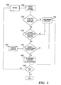
- a random stitch point is generated for the first row indicating the location in the stitch zone 20 where the master and slave scan lines 44, 46 are to be joined. If the randomly chosen stitch point falls between two white pixels 152, the stitch point is retained 154. If the randomly chosen stitch point does not fall between two white pixels 152, processing continues with block 156, which determines whether an alternate "all white” location for the stitch point is available within the stitch zone. If not, the original stitch point is retained 154. If an alternate "all white” location is available within the stitch zone, the algorithm determines 158 whether the alternate location falls within N-pixels from the original location of the stitch point. The value of N is controlled in block 160. If the alternate location is outside the N-pixel value, the original stitch point is retained 154. If acceptable 158, the alternate location is used 162 in lieu of the original stitch point. Processing subsequently continues for each remaining row 164, 166 of the image.
- Two dimensional randomizing algorithms similar to the one dimensional algorithms described above may also be employed.
- the two dimensional algorithms take into account not only the data within the row currently under consideration, but also the data within one or more adjacent rows. Again, several algorithms may be used, including "all white”, “all black”, and “zone boundary.” An example of the two dimensional "all white” algorithm is presented below.
- the best location for the stitch point falls between the white pixels at locations "V" and "W.”
- the original stitch point is retained if a better "all white” location is not available within the predetermined pixel range.
- Three dimensional algorithms follow the previously described one and two dimensional constructions except that three dimensions of data are analyzed.
- the data for each color is contained of a separate film master or printing plate.
- the algorithm considers data in two dimensions as previously described, but with further constraints on the data in the other color layers (e.g., separations) of the image.
- in-scan errors errors along the scan line, herein referred to as in-scan errors, such as gaps or overlaps, may occur at or adjacent the stitch point due to spinner synchronization errors, thermally induced variations, mechanical misalignment, and other factors.
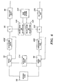
- the spin motors 48M, 48S of the master and slave imaging sources 32, 34 are synchronized to the same reference clock 90 as illustrated in FIG. 6.
- the rotational speed of the master spin motor 48M provided by a corresponding encoder, is fed back to the input of the master spin motor through a control loop 92.
- the rotational speed of the slave spin motor 48S again provided by an encoder, is fed back to the input of the slave spin motor 48S through a control loop 94.
- the control loops 92, 94 are configured to monitor the speed of each respective spin motor, and to adjust the speed, as necessary, to ensure that the motors are each rotating at the fixed rate required for imaging.
- the speed of the master spin motor 48M is additionally provided to the master pixel clock 96 through a phase locked loop (PLL) 98.
- the speed of the slave spin motor 48S is provided to the slave pixel clock 100 through a PLL 102.
- the output of the master and slave pixel ciocks 96, 100 are provided to the modulated laser sources 36 of the master and slave imaging sources 32, 34 to control the pixel data recording rate in the master and slave scan lines 44, 46. In this manner, time varying positional errors of the spin motors 48M, 48S, caused by load torque variations in each motor and other factors, are individually corrected by the corresponding PLL 98, 102 thereby ensuring an even spacing of recorded dots on the imaging media 42.
- Imaging errors in both the in-scan and cross-scan directions may occur, for example, in response to the expansion, contraction, or misalignment of the structure mounting the master and slave imaging sources 32, 34 relative to the imaging surface 43. Further, although the imaging sources 32, 34 are preferably mounted to a common support structure (not shown), such imaging errors generally do not affect the master and slave imaging sources 32, 34 identically.
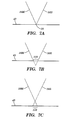
- Examples of in-scan errors are illustrated with reference to FIG. 7A, 7B, and 7C.
- the imaging beams 38M, 38S of the master and slave imaging sources 32, 34 meet at the random stitch point 18 as shown in FIG. 7A.
- the imaging beams 38M, 38S no longer meet at the stitch point 18, and a gap 110 is formed between the master and slave scan lines.
- the master and slave imaging beams 38M, 38S intersect prior to reaching the imaging surface, effectively forming an overlap 112 between the master and slave scan lines.
- the present invention compensates for these and other types of errors using a unique photodetector-based system.
- the measurement and correction of imaging errors is carried out using a photodetector system including a pair of photodetectors 120, 122, and a mask 124.
- the photodetectors 120, 122 are located in the image plane at one end of the imaging surface 43, outside the scanning area of the imaging system.
- the photodetectors 120, 122 are recessed into the imaging surface, and a suitably shaped recess 126 is provided for the mask 124 such that the mask surface is virtually coplanar to the imaging surface 43.
- a single photodetector may also be used in lieu of the pair of photodetectors 120, 122.
- the mask 124 is illustrated in greater detail in FIG. 9.
- the mask 124 includes a pair of back to back 30-60-90 triangular openings 128, 128', spaced apart a predetermined distance D corresponding to the width of the stitch zone 20, formed in an opaque support 130.
- the angles of the triangular openings 128, 128' may vary, however, based on the specific resolution of the imaging sources 32, 34 and other factors.
- the mask is formed of glass which is coated with an opaque material such as chromium. The coated glass has two uncoated areas which form two transparent triangles.
- the triangular openings 128, 128' are configured to lie directly above the photodetectors 120, 122.
- the relative in-scan position of the master and slave imaging beams 38M, 385 can be regulated using information provided by the photodetectors 120, 122.
- the master imaging beam 38M is scanned across the pair of triangular openings 128, 128' to determine the time it takes the beam 38M to pass from one end of the stitch zone 20, corresponding to the vertical edge 132 of the triangular opening 128, to the other end of the stitch zone 20, corresponding to the vertical edge 134 of the triangular opening 128'.
- the master imaging beam 38M passes over the triangular openings 128, 128', it creates a pulse on each of the photodetectors 120, 122.
- the time required to pass from the vertical edge 132 of the triangular opening 128 to the vertical edge 134 of the triangular opening 128' corresponds to the time between the end of the pulse detected by the photodetector 120 and the beginning of the pulse detected by photodetector 122.
- the master spin motor 48M should spin through an angle A in a time T as the master imaging beam 38M traverses the distance D. If, however, the imaging surface 43' moves closer to the master imaging source 32 as shown in FIG. 10, the time T' required to traverse the distance D between the vertical edges 132, 134 of the triangular openings 128, 128', as determined by the photodetectors 120, 122, increases, since the master spin motor 48M must spin through a larger angle A' (at the same angular velocity) to traverse the same distance D.
- a similar process is carried out using the slave imaging beam 38S to determine if the imaging surface 43 has moved relative to the slave imaging source 34.
- the imaging system 30 can substantially eliminate thermally induced in-scan errors such as gaps 110 and overlaps 112 between the master and scan lines 44, 46.
- a master beginning of line (BOL) shift and line length correction module 140 and a slave BOL shift and line length correction module 142 are provided to compensate for thermally induced in-scan errors in the master and slave scan lines 44, 46, respectively.
- Each of the modules 140, 142 receives beam information from a beam position detector 146 which acquires and analyzes the output from the photodetectors 120, 122. The output from each module 140, 142 is provided to a respective one of the PLL's 98, 102 to control the operation of the master and slave pixel clocks 96, 100.
- the length of the master and slave scan lines 44, 46 must be effectively "stretched" in time such that the correct number of pixels are imaged across a distance D in a nominal time T. This is achieved, for example, by imaging fewer pixels for each encoder count of the master and slave motors 48M, 48S, and by imaging through a greater number of encoder counts (i.e., through a larger angle A').
- the BOL of the master and slave scan lines 44, 46 must be shifted in position such that imaging ends (master) or starts (slave) at the stitch point 18, thereby eliminating the gap 110.
- the length of the master and slave scan lines 44, 46 must be effectively "compressed” in time to eliminate the overlap 112. This may be achieved, for example, by imaging a greater number of pixels for each encoder count of the master and slave motors 48M, 48S, and by imaging through fewer encoder counts (i.e., a smaller angle A''). Again, the BOL of the master and slave scan lines 44, 46 must be adjusted accordingly to ensure that imaging ends (master) or starts (slave) at the stitch point 18, thereby eliminating the overlap 112.
- the photodetectors 120, 122 and mask 124 can also be used to compensate for cross-scan error between the master and slave scan lines 44, 46. As with in-scan errors there can be several sources of cross-scan error, including, for example, velocity variations during the scan, and mechanical misalignment of the master and/or slave imaging sources 32, 34.
- FIG. 11 An example of a cross-scan error 170 between the master and slave scan lines 44, 46 is illustrated in FIG. 11. This error can be expressed in terms of line widths of the imaging addressability of the imaging sources 32, 34. In this example, a cross-scan error of 2.45 line widths exists between the master scan line 44 and the slave scan line 46.
- the imaging of the master scan line 44 must be delayed by 2.45 line widths. In accordance with the present invention, this can be accomplished in two steps.
- the imaging data for the master scan line 44 and the two following master scan lines 44', 44'' (FIG. 12) is buffered prior to being imaged by the master imaging source 32. This prevents the master scan lines 44, 44', 44'' from being imaged prior to the imaging of the lagging slave scan line 46.
- a rotational offset 174 (FIG. 6) of 0.45 line widths is applied to master motor 48M, such that the start of imaging of the master scan line 44 is further delayed by 0.45 line widths relative to the start of imaging of the slave scan line 46.
- the master scan line 44 is subsequently accessed from the buffer and recorded on the imaging media, and the process is repeated as necessary.
- the converse of the above-described method may be used in the case where the master scan line 44 lags the slave scan line 46.
- the degree of cross-scan error is measured by determining the difference in time required for the master and slave imaging beams 38M, 38S to pass across the triangular openings 128, 128', respectively, of the photodetector system. Specifically, as illustrated in FIG. 13, the master imaging beam 38M is passed over the triangular opening 128 as indicated by A, and the time required to pass from the hypotenuse H of the opening 128 to the vertical edge 132 thereof is detected by the underlying photodetector 120. Similarly, the slave imaging beam 38S is passed over the triangular opening 128' as indicated by B, and the time required to pass from the vertical edge 134 to the hypotenuse H' of the opening 128' is detected by the photodetector 122.
- the point of intersection of the master imaging beam 38M on the vertical edge 132 of the triangular opening 128 can be easily determined. The same applies to the intersection point of the slave imaging beam 38S on the vertical edge 134 of the triangular opening 128'. These values can then be compared to quantify the cross-scan error E.
- a mask including a single triangular opening is used to measure the cross-scan error.
- a single photodetector may be used.
- the cross-scan error is measured by sequentially imaging the master and slave imaging beams 38M, 38S over the triangular opening in the mask, and by comparing the time required for the imaging beams 38M, 38S to travel between the hypotenuse and vertical edge of the triangular opening.
- the in-scan and cross-scan error may be measured using a mask having other types of openings therethrough.
- the mask may include a triangular opening and a vertical slit, one or more angled and vertical slits, a combination of triangular openings and vertical/angled slits, or other suitably shaped openings.
- the in-scan error may be determined, for example, by measuring the time required for an imaging beam to pass from the vertical edge of a triangular opening to a vertical slit, or vice versa, or from one vertical slit to another vertical slit.
- the cross-scan error may be determined by comparing the time required for the master and slave imaging beams to travel between an angled and a vertical slit or vice versa.
- FIG. 14 A further feature of the present invention is illustrated in FIG. 14, wherein a pair of imaging sources 180, 182, which are configured to scan imaging beams 184, 186 in opposite directions, are used to image a composite scan line 188 formed of partial scan lines 190, 192.
- This configuration eliminates several error sources present in the imaging system previously described with regard to FIG. 3.
- the BOL 194, 196 of the partial scan lines 190, 192 are located in the center of the image, or elsewhere within the stitch zone 20 if a random stitch point is used.
- the partial scan lines 190, 192 begin at substantially the same location, the gap/overlap errors which may occur due to uncompensated velocity variations or thermal variations during the scan are eliminated. Small line length errors may still occur, but these errors will not produce highly noticeable artifacts in the final image.
- the use of the oppositely directed imaging sources 180, 182 also reduces cross-scan error as synchronization is established at the start of scan and any velocity variations which affect the cross-scan position of the beams due to the motion of the imaging surface in the cross-scan direction accumulate along the scan line and become an error in the line to line cross-scan spacing. This error is no more than already exists when using a single imaging system.
- a scanning system wherein a plurality of image capture systems, each including a linear array of photosensitive elements or the like (e.g., a linear charge coupled device (CCD) array), are used to capture and convert an image into partial scan lines of digital data.
- a scanning system is illustrated in FIG. 15, wherein a pair of image capture systems 200, 202, each including a respective linear CCD array 204, 206, are used to capture partial scan lines 208, 210 of an image 212.
- the digital data for the partial scan lines may be stitched together at random locations within a stitch zone as previously described herein to form composite scan lines.
- the random stitching of the present invention may also be used to form composite scan lines based on the partial scan lines produced by the image capture system of an X-Y scanning system.
Landscapes
- Engineering & Computer Science (AREA)
- Multimedia (AREA)
- Signal Processing (AREA)
- Physics & Mathematics (AREA)
- Optics & Photonics (AREA)
- General Engineering & Computer Science (AREA)
- General Physics & Mathematics (AREA)
- Theoretical Computer Science (AREA)
- Facsimile Scanning Arrangements (AREA)
- Laser Beam Printer (AREA)
- Apparatus For Radiation Diagnosis (AREA)
- Image Processing (AREA)
Applications Claiming Priority (2)
| Application Number | Priority Date | Filing Date | Title |
|---|---|---|---|
| US09/046,660 US6097418A (en) | 1998-03-24 | 1998-03-24 | Method and apparatus for combining a plurality of images without incurring a visible seam |
| US46660 | 1998-03-24 |
Publications (2)
| Publication Number | Publication Date |
|---|---|
| EP0946043A2 true EP0946043A2 (de) | 1999-09-29 |
| EP0946043A3 EP0946043A3 (de) | 2002-08-28 |
Family
ID=21944683
Family Applications (1)
| Application Number | Title | Priority Date | Filing Date |
|---|---|---|---|
| EP99200855A Withdrawn EP0946043A3 (de) | 1998-03-24 | 1999-03-19 | Verfahren und Vorrichtung zum Kombinieren von mehreren Bildern ohne eine sichbaren Naht zu erzeugen |
Country Status (3)
| Country | Link |
|---|---|
| US (1) | US6097418A (de) |
| EP (1) | EP0946043A3 (de) |
| JP (1) | JP2000033734A (de) |
Cited By (6)
| Publication number | Priority date | Publication date | Assignee | Title |
|---|---|---|---|---|
| EP1104165A3 (de) * | 1999-11-24 | 2002-07-24 | Xerox Corporation | Detektionssystem zum nahtlosen Schreiben mit mehreren Abbildungsgeräten |
| EP1289257A1 (de) * | 2001-08-22 | 2003-03-05 | Canon Kabushiki Kaisha | Bildverarbeitungsvorrichtung |
| WO2003055200A1 (en) * | 2001-12-19 | 2003-07-03 | Kodak Polychrome Graphics, Llc | Laser-induced thermal imaging with masking |
| WO2005039173A3 (en) * | 2003-10-20 | 2005-06-09 | Creo Il Ltd | Method and device for using multiple outputs of image sensor |
| US6943816B2 (en) | 2001-03-14 | 2005-09-13 | Kodak Polychrome Graphics Llc | Laser-induced thermal imaging with masking |
| US7154515B2 (en) | 2001-06-15 | 2006-12-26 | Perkinelmer, Inc. | Method and apparatus for reducing printing artifacts of stitched images |
Families Citing this family (13)
| Publication number | Priority date | Publication date | Assignee | Title |
|---|---|---|---|---|
| US6288818B1 (en) * | 1998-12-22 | 2001-09-11 | Ricoh Company, Ltd. | Optical scanning apparatus |
| US6433907B1 (en) * | 1999-08-05 | 2002-08-13 | Microvision, Inc. | Scanned display with plurality of scanning assemblies |
| JP2002318359A (ja) * | 2001-04-24 | 2002-10-31 | Ricoh Co Ltd | 光走査装置及び画像形成装置 |
| US20030115490A1 (en) * | 2001-07-12 | 2003-06-19 | Russo Anthony P. | Secure network and networked devices using biometrics |
| US7127090B2 (en) | 2001-07-30 | 2006-10-24 | Accuimage Diagnostics Corp | Methods and systems for combining a plurality of radiographic images |
| US7650044B2 (en) * | 2001-07-30 | 2010-01-19 | Cedara Software (Usa) Limited | Methods and systems for intensity matching of a plurality of radiographic images |
| JP4841086B2 (ja) * | 2001-09-26 | 2011-12-21 | 株式会社リコー | 画像形成装置 |
| US7068296B2 (en) * | 2001-09-14 | 2006-06-27 | Ricoh Company, Ltd. | Optical scanning device for reducing a dot position displacement at a joint of scanning lines |
| US6729234B2 (en) | 2002-04-05 | 2004-05-04 | Agfa Corporation | Actuation system in an imaging system |
| US6772688B2 (en) | 2002-04-05 | 2004-08-10 | Agfa Corporation | Imaging system with automated plate locating mechanism and method for loading printing plate |
| US20030189611A1 (en) * | 2002-04-08 | 2003-10-09 | Fan Tai-Lin | Jet printer calibration |
| US7271822B2 (en) * | 2004-07-28 | 2007-09-18 | Hewlett-Packard Development Company, L.P. | Seamless stitching of multiple image fields in a wide-format laser printer |
| US10602432B2 (en) | 2015-05-14 | 2020-03-24 | Samsung Electronics Co., Ltd. | Method and apparatus for searching networks |
Family Cites Families (10)
| Publication number | Priority date | Publication date | Assignee | Title |
|---|---|---|---|---|
| US4206348A (en) * | 1978-06-05 | 1980-06-03 | Eastman Kodak Company | Optical scanner with electrooptical feedback for beam positioning |
| US4940304A (en) * | 1987-06-03 | 1990-07-10 | Fuji Photo Film Co., Ltd. | Optical deflecting apparatus |
| US5107280A (en) * | 1989-09-12 | 1992-04-21 | Brother Kogyo Kabushiki Kaisha | Divisional exposure apparatus |
| JP3207497B2 (ja) * | 1992-03-10 | 2001-09-10 | キヤノン株式会社 | 画像形成装置 |
| US5257048A (en) * | 1993-02-16 | 1993-10-26 | Xerox Corporation | Optical element and photoreceptor registration system for a raster output scanner in an electrophotographic printer |
| JP3191232B2 (ja) * | 1993-06-29 | 2001-07-23 | コニカ株式会社 | 画像形成装置 |
| US5357106A (en) * | 1993-10-01 | 1994-10-18 | Xerox Corporation | Sensor for detecting beam position and start of scan position |
| DE69519221T2 (de) * | 1995-02-22 | 2001-06-13 | Barco Graphics, Zwijnaarde | Abtastgerät |
| US5930019A (en) * | 1996-12-16 | 1999-07-27 | Fuji Xerox Co., Ltd. | Light scanning device, optical device, and scanning method of optical device |
| JPH10197811A (ja) * | 1997-01-14 | 1998-07-31 | Asahi Optical Co Ltd | カスケード走査光学系 |
-
1998
- 1998-03-24 US US09/046,660 patent/US6097418A/en not_active Expired - Fee Related
-
1999
- 1999-03-19 EP EP99200855A patent/EP0946043A3/de not_active Withdrawn
- 1999-03-24 JP JP11079780A patent/JP2000033734A/ja active Pending
Cited By (9)
| Publication number | Priority date | Publication date | Assignee | Title |
|---|---|---|---|---|
| EP1104165A3 (de) * | 1999-11-24 | 2002-07-24 | Xerox Corporation | Detektionssystem zum nahtlosen Schreiben mit mehreren Abbildungsgeräten |
| US6943816B2 (en) | 2001-03-14 | 2005-09-13 | Kodak Polychrome Graphics Llc | Laser-induced thermal imaging with masking |
| US7154515B2 (en) | 2001-06-15 | 2006-12-26 | Perkinelmer, Inc. | Method and apparatus for reducing printing artifacts of stitched images |
| EP1289257A1 (de) * | 2001-08-22 | 2003-03-05 | Canon Kabushiki Kaisha | Bildverarbeitungsvorrichtung |
| US7123388B2 (en) | 2001-08-22 | 2006-10-17 | Canon Kabushiki Kaisha | Image processing apparatus |
| WO2003055200A1 (en) * | 2001-12-19 | 2003-07-03 | Kodak Polychrome Graphics, Llc | Laser-induced thermal imaging with masking |
| US6888558B2 (en) | 2001-12-19 | 2005-05-03 | Kodak Polychrome Graphics, Llc | Laser-induced thermal imaging with masking |
| WO2005039173A3 (en) * | 2003-10-20 | 2005-06-09 | Creo Il Ltd | Method and device for using multiple outputs of image sensor |
| US7907190B2 (en) | 2003-10-20 | 2011-03-15 | Eastman Kodak Company | Image sensor multiple output method |
Also Published As
| Publication number | Publication date |
|---|---|
| JP2000033734A (ja) | 2000-02-02 |
| EP0946043A3 (de) | 2002-08-28 |
| US6097418A (en) | 2000-08-01 |
Similar Documents
| Publication | Publication Date | Title |
|---|---|---|
| US6097418A (en) | Method and apparatus for combining a plurality of images without incurring a visible seam | |
| US6195471B1 (en) | Method and apparatus for combining a plurality of images at random stitch points without incurring a visible seam | |
| US7213900B2 (en) | Recording sheet and image recording apparatus | |
| US6847390B2 (en) | Method and apparatus for image forming capable of effectively adjusting an image recording start position | |
| JPH05241258A (ja) | 立体画像記録方法および立体画像記録装置 | |
| JP2001221976A (ja) | 大判のレンチキュラ画像を印刷する方法及び装置 | |
| US6891630B1 (en) | Image recording method and image recording apparatus | |
| JP4233137B2 (ja) | 位置決め誤差自動補償機能を有するスキャナー装置 | |
| JP2001208991A (ja) | フォトニックイメージャの並列書き込みによって幅広で継ぎ目のない電子写真画像を作成するセンシングシステム | |
| EP2116908B1 (de) | Bilderzeugungsvorrichtung, Steuerungsverfahren dafür und computerlesbares Speichermedium | |
| JP3191794B2 (ja) | 画像読取装置 | |
| JPH0933834A (ja) | 2ビームレーザー走査光学系 | |
| US5249069A (en) | Method and apparatus for automatic alignment of front and rear scanning cameras | |
| EP0910040A2 (de) | Verfahren zur Kompensation von Verzerrungen zwischen Blöcken eines abegetasteten Bildes | |
| US6384942B1 (en) | Image scanning unit | |
| JP2010115904A (ja) | 画像形成装置および画像形成装置制御プログラム | |
| US7187398B2 (en) | Characterization of a scan line produced from a facet of a scanning device | |
| US20020131060A1 (en) | Process and apparatus for the digital production of a picture | |
| JP3637180B2 (ja) | 画像形成装置 | |
| JP2746788B2 (ja) | 立体画像記録装置 | |
| JPS5937910B2 (ja) | 光プリンタの走査方式 | |
| JPH04369158A (ja) | シリアル走査型プリンタ | |
| JP2003266756A (ja) | 画像処理装置および画像形成装置 | |
| JP3202709B2 (ja) | カラー画像形成装置に対する画像ゆがみ補正方法 | |
| JPH1117892A (ja) | 画像処理装置 |
Legal Events
| Date | Code | Title | Description |
|---|---|---|---|
| PUAI | Public reference made under article 153(3) epc to a published international application that has entered the european phase |
Free format text: ORIGINAL CODE: 0009012 |
|
| AK | Designated contracting states |
Kind code of ref document: A2 Designated state(s): AT BE CH CY DE DK ES FI FR GB GR IE IT LI LU MC NL PT SE |
|
| AX | Request for extension of the european patent |
Free format text: AL;LT;LV;MK;RO;SI |
|
| PUAL | Search report despatched |
Free format text: ORIGINAL CODE: 0009013 |
|
| AK | Designated contracting states |
Kind code of ref document: A3 Designated state(s): AT BE CH CY DE DK ES FI FR GB GR IE IT LI LU MC NL PT SE |
|
| AX | Request for extension of the european patent |
Free format text: AL;LT;LV;MK;RO;SI |
|
| 17P | Request for examination filed |
Effective date: 20030228 |
|
| AKX | Designation fees paid |
Designated state(s): DE FR GB |
|
| STAA | Information on the status of an ep patent application or granted ep patent |
Free format text: STATUS: THE APPLICATION HAS BEEN WITHDRAWN |
|
| 18W | Application withdrawn |
Effective date: 20040205 |