EP0945372B1 - Vorrichtung und Verfahren zum Transportieren von stückigem Produkt - Google Patents
Vorrichtung und Verfahren zum Transportieren von stückigem Produkt Download PDFInfo
- Publication number
- EP0945372B1 EP0945372B1 EP19990105607 EP99105607A EP0945372B1 EP 0945372 B1 EP0945372 B1 EP 0945372B1 EP 19990105607 EP19990105607 EP 19990105607 EP 99105607 A EP99105607 A EP 99105607A EP 0945372 B1 EP0945372 B1 EP 0945372B1
- Authority
- EP
- European Patent Office
- Prior art keywords
- drive
- chain
- walls
- parallel
- spar
- Prior art date
- Legal status (The legal status is an assumption and is not a legal conclusion. Google has not performed a legal analysis and makes no representation as to the accuracy of the status listed.)
- Expired - Lifetime
Links
- 238000000034 method Methods 0.000 title description 4
- 230000033001 locomotion Effects 0.000 claims description 26
- 238000006073 displacement reaction Methods 0.000 claims description 14
- 230000001360 synchronised effect Effects 0.000 claims description 3
- 230000005540 biological transmission Effects 0.000 description 4
- 238000003780 insertion Methods 0.000 description 4
- 230000037431 insertion Effects 0.000 description 4
- 230000007423 decrease Effects 0.000 description 2
- 238000004806 packaging method and process Methods 0.000 description 2
- 235000003332 Ilex aquifolium Nutrition 0.000 description 1
- 241000209027 Ilex aquifolium Species 0.000 description 1
- 230000003111 delayed effect Effects 0.000 description 1
- 230000001419 dependent effect Effects 0.000 description 1
- 238000003754 machining Methods 0.000 description 1
- 238000004519 manufacturing process Methods 0.000 description 1
- 238000012858 packaging process Methods 0.000 description 1
- 238000012856 packing Methods 0.000 description 1
- 238000007789 sealing Methods 0.000 description 1
- 238000003466 welding Methods 0.000 description 1
Images


Classifications
-
- B—PERFORMING OPERATIONS; TRANSPORTING
- B65—CONVEYING; PACKING; STORING; HANDLING THIN OR FILAMENTARY MATERIAL
- B65G—TRANSPORT OR STORAGE DEVICES, e.g. CONVEYORS FOR LOADING OR TIPPING, SHOP CONVEYOR SYSTEMS OR PNEUMATIC TUBE CONVEYORS
- B65G17/00—Conveyors having an endless traction element, e.g. a chain, transmitting movement to a continuous or substantially-continuous load-carrying surface or to a series of individual load-carriers; Endless-chain conveyors in which the chains form the load-carrying surface
- B65G17/26—Conveyors having an endless traction element, e.g. a chain, transmitting movement to a continuous or substantially-continuous load-carrying surface or to a series of individual load-carriers; Endless-chain conveyors in which the chains form the load-carrying surface comprising a series of co-operating units, e.g. interconnected by pivots
-
- B—PERFORMING OPERATIONS; TRANSPORTING
- B65—CONVEYING; PACKING; STORING; HANDLING THIN OR FILAMENTARY MATERIAL
- B65G—TRANSPORT OR STORAGE DEVICES, e.g. CONVEYORS FOR LOADING OR TIPPING, SHOP CONVEYOR SYSTEMS OR PNEUMATIC TUBE CONVEYORS
- B65G2201/00—Indexing codes relating to handling devices, e.g. conveyors, characterised by the type of product or load being conveyed or handled
- B65G2201/02—Articles
Definitions
- the invention relates to a device for transporting lumpy product a rotating transport device, at least one drive for the circulation of the Transport device, and with transversely to the transport direction on the transport device arranged walls, with two arranged one behind the other
- a space for a lumpy product is spared with two walls parallel strands, with interlocking walls, and with a drive for Moving the walls to each other, a control device being provided the rooms are wider or narrower depending on the time of operation adjust.
- the known devices have the disadvantage that the rooms are not transverse to Direction of transport can be changed so that a successive Transport of products of different depths cannot be met.
- the object of the invention is to eliminate this disadvantage.
- the rooms can also be changed transversely to the direction of transport.
- the distance between the chain bars can be adjusted in this regard, if a chain spar is perpendicular to the direction of movement of the chain spar Changing the distance between the chain bars by means of a device is displaceable, and the device is connected to the control device.
- Between The existing, lumpy product walls can be parallel to Transport boundaries, lateral boundaries transverse to the transport direction be limited or pinched. For a particularly tight enclosure of the Product can also pinch the product in two perpendicular to each other extending directions are provided.
- the chain spars during a transport movement Spaces between the walls in the transport direction or perpendicular to it limits that the lumpy product is held firmly and that during a Interrupting the transport movement the rooms are enlarged.
- a drive is provided for a circular movement of a chain spar (Claim 2), the chain bars can be operated differently and thereby can be moved against each other, or a separate drive next to the individual drives of the chain spars only affect one chain spar and the latter driving drive.
- the drive for parallel adjustment of the walls is one of the drives for the orbital movement of the chain spars (claim 4).
- a time shift Operation e.g. a delayed start of an orbital movement of the two chain spars the chain spars and thus the walls are moved by the distance to each other, that was covered by the chain spar operated first within the time difference.
- there is an increase or decrease in the distance between the walls e.g. a control with respect to Speed of the drive or a combined control with regard to the switching time and the speed (claim 5) possible.
- the functional sequence is free programmable.
- the rooms can also be designed analogously by means of an embodiment of the device 6 can be adjusted.
- a drive acts for the circular movement of a chain spar via a gear on a parallel section of a chain spar, and the drive together with the gear is parallel to the direction of movement of the with the gear interacting part of the chain spar by means of a drive for parallel Adjustable chain spar adjustment.
- a drive for parallel Adjustable chain spar adjustment By just shifting the Drive for the orbital movement with the help of the drive for parallel adjustment depending on the mode of operation, one chain spar is slightly opposite the other Chain spar twisted so that the wall clearances change. This Relative shift can be done by means of a spindle (claim 7).
- a spindle works precisely, reliably and sufficiently with a relatively low moment of inertia fast.
- a chain spar for the Orbital movement shifted from drive to parallel adjustment of the walls become. This technical solution is especially for relatively light chain posts suitable.
- Identical chain spars (claim 9) have the advantage that on the one hand the technical Effort to manufacture the two chain spars is minimized. On the other hand, one Adjustment to a result that is independent of which chain spar for one Change in space was adjusted.
- Murlubric® has proven itself as the material for the chain guides (claim 11). This Plastic in particular has a high notch resistance.
- the rate of introduction of a lumpy product into a room is at least ten times greater than the speed of the transport device, are relative narrow spaces still suitable for quick product introduction and the maximum Transport speed can be increased further.
- the insertion speed is independent of one Fall speed can be increased and bag-in-box systems can be set up very quickly be generated.
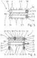
- a device 1 for transporting lumpy product 2 with a revolving transport device 3 two drives 4, 5 for the circulation of the Transport device 3, and with walls 6 arranged transversely to the transport direction 9, 7, there is a space 8 between two walls 6, 7 arranged one behind the other a lumpy product 2 recessed ( Figure 1).
- the transport device 3 consists of two separate chain spars 10, 11 arranged parallel to each other, which in clocked way with transportation breaks ..
- the walls 6 of the Chain spar 10 protrude into the walls 7 of the chain spar 11 such that a alternating row of parallel to one another and transverse to the transport device 9 aligned walls 6.7 is present.
- the drives 4, 5 are each for one Orbital movement of a chain spar 10, 11 is provided.
- the drives 4, 5 are Servomotors 12, 13.
- the drive 4 for the circular movement of the chain spar 10 is at the same time a drive 14 for parallel adjustment of the walls 6, 7.
- the drive 4 for parallel adjustment of the walls 6, 7 is by means of a control device 38 with respect its speed controlled so that it reduces the distance of the Walls 6, 7 in empty rooms 8 rotate faster than that for a short period of time Drive 5 so that the chain spar 10 makes a parallel displacement in the transport direction 9 experienced against the chain spar 11.
- the device 1 can be narrower Transport the lumpy product 2 tightly between the walls 6, 7.
- the walls 6, 7 are slightly further apart ( Figure 2), so that easier insertion of the product 2 in a room 8 or easier removal of product 2 can be done from a room 8.
- control device 38 controls drive 4 as a function of Operating state, d. H. of the clock sequences.
- the drives 4, 5 are electronic to each other synchronized.
- the chain bars 10, 11 are identical.
- a chain spar 10, 11 is made in each case essentially from a lateral boundary 15, 16 on which the walls 6, 7 are attached equidistantly.
- Only the stationary drive 4 moves via its gear 17 the chain spar 10 relative to the chain spar 11 and moves the chain spar 10 uniformly around outside of a displacement process.
- the other drive 5 only moves the chain spar 11 outside of a space change period the transmission 18 with the same rotational speed as the chain spar 10. Zur Increasing the distance between the walls 6, 7 rotates the drive 4 for one corresponding time period slower than the drive 5, so that the chain spar 10 a Parallel displacement against the transport direction 9 with respect to the chain spar 11 experiences.
- a drive 4 acts for the Orbital movement of a chain spar 10 via a gear 17 on one Parallel section 19 of the chain spar 10.
- the drive 4 together with the gear 17 parallel to the direction of movement (transport direction 9) of the cooperating with the gear 17 Part 20 of the chain spar 10 by means of a drive 14 for parallel Adjustment of the walls 6, 7 slidable.
- the drive 14 is a stationary servo motor 21 by a control device 38 analogous to the previous embodiment is controlled.
- the drive 14 is via a spindle 22 with the drive 4 for the Orbital movement connected and can move the drive 4.
- the Spindle body 23 is rigidly connected to drive 4 via a connection 24.
- the drives 4, 5 are each on one Deflection wheel 26 of a rotating chain spar 10, 11 arranged and drive the Deflection wheels 26 axially.
- the drive 4 for the circular movement of the chain spar 10 is also a drive 14 for adjusting the walls 6, 7 to each other.
- a Adjustment is realized such that the drive 14 by the function of Control device 38 stopped at a time delay to drive 5 at a cycle standstill becomes.
- the chain spar 10 is complete its drive 4 from a drive 14 for parallel adjustment of the walls 6, 7 displaceable.
- the drive 14 is part of a device 27 for moving the Chain spar 10 parallel to the transport direction 9.
- the device 27 has one Rack 28, which is connected to the axes 29 of the planet gears 26, and on which the stationary drive 14 acts with its gear 30.
- the second chain spar 11 is perpendicular to the direction of movement of the chain spar in order to change the Distance of the chain spars 10, 11 and thus the spaces 8 in this direction a device 31 for displacement.
- the device 31 for Moving essentially consists of the drives 32, 33, each of which has a Gear 34, 35 by means of a rack 36, 37 on an axis 29 of a deflection wheel 26 act.
- the drives 32, 33 are operated and adjusted synchronously with one another thus the distance between the chain spars 10, 11 according to the operating state.
- Three Control devices 38 provide an increase in space both in parallel and perpendicular to the direction of transport 9.
Landscapes
- Engineering & Computer Science (AREA)
- Mechanical Engineering (AREA)
- Auxiliary Devices For And Details Of Packaging Control (AREA)
- Control Of Conveyors (AREA)
- Special Conveying (AREA)
Description
- Figur 1
- in einer Draufsicht einen Teil einer Vorrichtung zum Transportieren von stükkigem Produkt mit zwei separat mittels Antrieben angetriebenen, parallel zueinander angeordneten Kettenholmen, deren Wände stückiges Produkt mitnehmen; wobei ein Antrieb mit einer Steuereinrichtung zum Verstellen der Breite der zwischen den Wänden befindlichen Räume verbunden ist;
- Figur 2
- in einer Draufsicht den Teil der Vorrichtung der Figur 1, jedoch mit geringfügig größerem Wandabstand, wobei der vergrößerte Wandabstand durch unterschiedlichen Betrieb der beiden ortsfesten Antriebe realisiert wurde;
- Figur 3
- in einer Draufsicht einen Teil einer Vorrichtung entsprechend Figur 1, jedoch mit einem verschiebbaren Antrieb für einen Kettenholm, wobei die Verschiebung durch die Funktion einer Steuereinrichtung von einem weiteren ortsfesten Antrieb über eine Spindel erreicht wird;
- Figur 4
- in einer Draufsicht den Teil der Vorrichtung der Figur 3, jedoch mit infolge der Spindelbetätigung verschobenem Antrieb mitsamt Kettenholm, sowie mit schmalerem Produkt;
- Figur 5
- in einer Draufsicht eine Vorrichtung zum Transportieren von stückigem Produkt mit zwei horizontal umlaufenden Kettenholmen, und jeweils einem Antrieb an einem Umlenkrad, wobei an einem Antrieb eine Steuereinrichtung vorgesehen ist, sowie
- Figur 6
- in einer Draufsicht eine Vorrichtung entsprechend Figur 5, jedoch mit einer Einrichtung zur Verschiebung eines Kettenholms parallel zur Transportrichtung, einer Einrichtung zur Verschiebung des anderen Kettenholms senkrecht zur Transportrichtung des stückigen Produkts, und mit drei Steuereinrichtungen.
- 1
- Vorrichtung
- 2
- Produkt
- 3
- Transporteinrichtung
- 4, 5
- Antrieb
- 6, 7
- Wand
- 8
- Raum
- 9
- Transportrichtung
- 10, 11
- Kettenholm
- 12, 13
- Servomotor
- 14
- Antrieb
- 15, 16
- Begrenzung
- 17, 18
- Getriebe
- 19
- Parallelabschnitt
- 20
- zusammenwirkendes Teil
- 21
- Servomotor
- 22
- Spindel
- 23
- Spindelkörper
- 24
- Verbindung
- 25
- Gleitbahn
- 26
- Umlenkrad
- 27
- Einrichtung zum Verschieben
- 28
- Zahnstange
- 29
- Achse
- 30
- Getriebe
- 31
- Einrichtung zum Verschieben
- 32, 33
- Antrieb
- 34, 35
- Getriebe
- 36, 37
- Zahnstange
- 38
- Steuereinrichtung
Claims (11)
- Vorrichtung zum Transportieren von stückigem Produkt (12) mit einer umlaufenden Transporteinrichtung (3), mindestens einem Antrieb (4, 5) für den Umlauf der Transporteinrichtung (3) und mit quer zur Transportrichtung (9) an der Transporteinrichtung (3) angeordneten Wänden (6, 7), wobei zwischen jeweils zwei hintereinander angeordneten Wänden (6, 7) ein Raum (8) für ein stückiges Produkt (2) ausgespart ist, die Transporteinrichtung (3) aus zwei separaten, parallel zueinander angeordneten Strängen mit auf die Stränge zu ausgerichteten Wänden (6, 7) besteht, die Wände (6, 7) der beiden Stränge (10, 11) alternierend ineinandergreifen, und mindestens ein Antrieb (14) zur Verschiebung der Wände (6, 7) zueinander vorgesehen ist, wobei eine Steuereinrichtung (38) vorgesehen ist, mittels der die Räume (8) abhängig vom Betriebszeitpunkt breiter oder schmäler eingestellt werden können, dadurch gekennzeichnet, dass die Stränge als Kettenholme (10, 11) ausgeführt sind, dass ein Kettenholm (11) senkrecht zur Bewegungsrichtung des Kettenholms (11) zur Veränderung des Abstandes der Kettenholme (10, 11) zueinander mittels einer Einrichtung (31) zum Verschieben verschiebbar ist, und dass die Einrichtung (31) mit der Steuereinrichtung (38) verbunden ist.
- Vorrichtung nach Anspruch 1, dadurch gekennzeichnet, dass jeweils ein Antrieb (4,5) für eine Umlaufbewegung eines Kettenholms (10, 11) vorgesehen ist.
- Vorrichtung nach Anspruch 1 oder Anspruch 2, dadurch gekennzeichnet, dass als Antrieb (4, 5, 14) ein Servomotor (12, 13, 21) vorgesehen ist.
- Vorrichtung nach Anspruch 2, dadurch gekennzeichnet, dass der Antrieb (14) zur parallelen Verstellung der Wände (6, 7) einer der Antriebe (4) für die Umlaufbewegung eines Kettenholmes (10) ist, und dass der Antrieb (14) mit der Steuereinrichtung (38) verbunden ist.
- Vorrichtung nach Anspruch 4, dadurch gekennzeichnet, dass der Antrieb (4) zur parallelen Verstellung der Wände (6, 7) bzgl. seiner Drehzahl und/oder seiner Schaltzeit von der Steuereinrichtung (38) ansteuerbar ist.
- Vorrichtung nach Anspruch 1, dadurch gekennzeichnet, dass ein Antrieb (4) für die Umlaufbewegung eines Kettenholms (10) über ein Getriebe (17) auf einen Parallelabschnitt (19) des Kettenholmes (10) wirkt, und dass der Antrieb (4) mitsamt dem Getriebe (17) parallel zur Bewegungsrichtung des mit dem Getriebe (17) zusammenwirkenden Teils (20) des Kettenholms (10) mittels eines Antriebs (14) zur parallelen Verstellung der Wände (6, 7, 10) verschiebbar ist.
- Vorrichtung nach Anspruch 1 oder Anspruch 6, dadurch gekennzeichnet, dass der Antrieb (14) zur parallelen Verstellung der Wände (6, 7) über eine Spindel (22) mit dem Antrieb (4) für die Umlaufbewegung verbunden ist.
- Vorrichtung nach Anspruch 1, Anspruch 2 oder Anspruch 7, dadurch gekennzeichnet, dass ein Kettenholm (10) für die Umlaufbewegung vom Antrieb (14) zur parallelen Verstellung der Wände (6, 7) verschiebbar ist.
- Vorrichtung nach Anspruch 1, dadurch gekennzeichnet, dass die Kettenholme (10, 11) baugleich ausgestaltet sind.
- Vorrichtung nach Anspruch 1, dadurch gekennzeichnet, dass die Antriebe (4, 5, 14) zeitweise elektronisch miteinander synchronisiert sind.
- Vorrichtung nach Anspruch 1, dadurch gekennzeichnet, dass Kettenführungen aus Murlubric® vorgesehen sind.
Applications Claiming Priority (2)
| Application Number | Priority Date | Filing Date | Title |
|---|---|---|---|
| DE19813120 | 1998-03-25 | ||
| DE19813120A DE19813120A1 (de) | 1998-01-09 | 1998-03-25 | Vorrichtung und Verfahren zum Transportieren von stückigem Produkt |
Publications (3)
| Publication Number | Publication Date |
|---|---|
| EP0945372A2 EP0945372A2 (de) | 1999-09-29 |
| EP0945372A3 EP0945372A3 (de) | 2000-09-06 |
| EP0945372B1 true EP0945372B1 (de) | 2003-05-28 |
Family
ID=7862267
Family Applications (1)
| Application Number | Title | Priority Date | Filing Date |
|---|---|---|---|
| EP19990105607 Expired - Lifetime EP0945372B1 (de) | 1998-03-25 | 1999-03-19 | Vorrichtung und Verfahren zum Transportieren von stückigem Produkt |
Country Status (2)
| Country | Link |
|---|---|
| EP (1) | EP0945372B1 (de) |
| ES (1) | ES2199497T3 (de) |
Families Citing this family (1)
| Publication number | Priority date | Publication date | Assignee | Title |
|---|---|---|---|---|
| JP2001240236A (ja) * | 2000-03-01 | 2001-09-04 | Shikoku Kakoki Co Ltd | コンベヤ |
Family Cites Families (4)
| Publication number | Priority date | Publication date | Assignee | Title |
|---|---|---|---|---|
| AU8158682A (en) * | 1981-03-17 | 1982-09-23 | Hoehn, J.W. | Conveyor |
| JPS6052407A (ja) * | 1983-09-01 | 1985-03-25 | Shibuya Mach Kk | チエ−ンコンベアの位相調整装置 |
| IT1248234B (it) * | 1991-06-14 | 1995-01-05 | Gd Spa | Dispositivo per la ricezione ed il trasferimento di prodotti o pile di prodotti sostanzialmente parallelepipedi ad un successivo convogliatore. |
| JPH0826437A (ja) * | 1994-07-11 | 1996-01-30 | Fuji Photo Film Co Ltd | ワーク移送方法及び移送装置 |
-
1999
- 1999-03-19 EP EP19990105607 patent/EP0945372B1/de not_active Expired - Lifetime
- 1999-03-19 ES ES99105607T patent/ES2199497T3/es not_active Expired - Lifetime
Also Published As
| Publication number | Publication date |
|---|---|
| ES2199497T3 (es) | 2004-02-16 |
| EP0945372A3 (de) | 2000-09-06 |
| EP0945372A2 (de) | 1999-09-29 |
Similar Documents
| Publication | Publication Date | Title |
|---|---|---|
| EP1784350B1 (de) | Vorrichtung zum gruppieren von stückgut | |
| DE3405787C2 (de) | Klebeband-Verschlußmaschine für Faltbehälter | |
| DE69220206T2 (de) | Querheissversiegelungseinrichtung in einer beutelherstellungsmaschine | |
| EP3334669B1 (de) | Transportvorrichtung sowie transportverfahren mit einer derartigen transportvorrichtung | |
| EP3837196B1 (de) | Transportvorrichtung mit transportrechen und gegenrechen | |
| EP3400805B1 (de) | Vorrichtung und verfahren zum übergeben und einlegen von würstchengruppen in eine verpackung | |
| EP2826735B1 (de) | Einstellbarer Speicherabschnitt einer Fördereinrichtung und Verfahren zum Zwischenspeichern von Artikeln | |
| EP2035283A1 (de) | Vorrichtung zur behandlung von flexiblen schlauchartigen gebilden mit wenigstens einer öffnung | |
| CH418956A (de) | Maschine zum Kartonieren von Füllgut aller Art | |
| DE10201182A1 (de) | Positioniersystem | |
| EP3034415A1 (de) | Verfahren zum Übertragen von Packgut in Behältnisse und zum Weitertransport der befüllten Behältnisse | |
| DE69507264T2 (de) | Einrichtung zum Bilden geordneter Gruppen aus einem ebenen Strom von Gegenständen, insbesondere für automatische Verpackungssysteme | |
| DE10301178B4 (de) | Vorrichtung zum Ausrichten und Verteilen | |
| EP3366614B1 (de) | Zufuhrketten-einheit | |
| EP1902980A1 (de) | Reversierende Vorschubeinrichtung zum taktweisen linearen Vorschieben von Gutstapeln über eine Transportstrecke | |
| DE3819348C1 (de) | ||
| EP0413927A1 (de) | Vorrichtung zur Herstellung einer Flüssigkeitspackung | |
| EP3045410A1 (de) | Vorrichtung und verfahren zum wenden und transportieren von stückgut | |
| EP1053066B1 (de) | Fördervorrichtung | |
| DE3702954A1 (de) | Gruppiereinrichtung zur bildung von behaeltergruppen | |
| DE60319892T2 (de) | Artikelpositioniermaschine | |
| DE19813120A1 (de) | Vorrichtung und Verfahren zum Transportieren von stückigem Produkt | |
| EP0945372A2 (de) | Vorrichtung und Verfahren zum Transportieren von stückigem Produkt | |
| DE19803297A1 (de) | Vorrichtung zum Transportieren von stückigem Produkt | |
| DE10204933A1 (de) | Vorrichtung zum Transportieren von stückigem Produkt |
Legal Events
| Date | Code | Title | Description |
|---|---|---|---|
| PUAI | Public reference made under article 153(3) epc to a published international application that has entered the european phase |
Free format text: ORIGINAL CODE: 0009012 |
|
| 17P | Request for examination filed |
Effective date: 19990419 |
|
| AK | Designated contracting states |
Kind code of ref document: A2 Designated state(s): BE DE ES FR GB IT NL |
|
| AX | Request for extension of the european patent |
Free format text: AL;LT;LV;MK;RO;SI |
|
| PUAL | Search report despatched |
Free format text: ORIGINAL CODE: 0009013 |
|
| AK | Designated contracting states |
Kind code of ref document: A3 Designated state(s): AT BE CH CY DE DK ES FI FR GB GR IE IT LI LU MC NL PT SE |
|
| AX | Request for extension of the european patent |
Free format text: AL;LT;LV;MK;RO;SI |
|
| 17Q | First examination report despatched |
Effective date: 20001123 |
|
| AKX | Designation fees paid |
Free format text: BE DE ES FR GB IT NL |
|
| GRAH | Despatch of communication of intention to grant a patent |
Free format text: ORIGINAL CODE: EPIDOS IGRA |
|
| GRAH | Despatch of communication of intention to grant a patent |
Free format text: ORIGINAL CODE: EPIDOS IGRA |
|
| GRAA | (expected) grant |
Free format text: ORIGINAL CODE: 0009210 |
|
| AK | Designated contracting states |
Designated state(s): BE DE ES FR GB IT NL |
|
| REG | Reference to a national code |
Ref country code: GB Ref legal event code: FG4D Free format text: NOT ENGLISH |
|
| REF | Corresponds to: |
Ref document number: 59905699 Country of ref document: DE Date of ref document: 20030703 Kind code of ref document: P |
|
| GBT | Gb: translation of ep patent filed (gb section 77(6)(a)/1977) | ||
| ET | Fr: translation filed | ||
| REG | Reference to a national code |
Ref country code: ES Ref legal event code: FG2A Ref document number: 2199497 Country of ref document: ES Kind code of ref document: T3 |
|
| PLBE | No opposition filed within time limit |
Free format text: ORIGINAL CODE: 0009261 |
|
| STAA | Information on the status of an ep patent application or granted ep patent |
Free format text: STATUS: NO OPPOSITION FILED WITHIN TIME LIMIT |
|
| 26N | No opposition filed |
Effective date: 20040302 |
|
| PGFP | Annual fee paid to national office [announced via postgrant information from national office to epo] |
Ref country code: IT Payment date: 20060331 Year of fee payment: 8 |
|
| PGFP | Annual fee paid to national office [announced via postgrant information from national office to epo] |
Ref country code: NL Payment date: 20070313 Year of fee payment: 9 |
|
| PGFP | Annual fee paid to national office [announced via postgrant information from national office to epo] |
Ref country code: GB Payment date: 20070322 Year of fee payment: 9 |
|
| PGFP | Annual fee paid to national office [announced via postgrant information from national office to epo] |
Ref country code: ES Payment date: 20070329 Year of fee payment: 9 |
|
| PGFP | Annual fee paid to national office [announced via postgrant information from national office to epo] |
Ref country code: DE Payment date: 20070524 Year of fee payment: 9 |
|
| PGFP | Annual fee paid to national office [announced via postgrant information from national office to epo] |
Ref country code: BE Payment date: 20070419 Year of fee payment: 9 |
|
| PGFP | Annual fee paid to national office [announced via postgrant information from national office to epo] |
Ref country code: FR Payment date: 20070319 Year of fee payment: 9 |
|
| BERE | Be: lapsed |
Owner name: *ROVEMA VERPACKUNGSMASCHINEN G.M.B.H. Effective date: 20080331 |
|
| GBPC | Gb: european patent ceased through non-payment of renewal fee |
Effective date: 20080319 |
|
| PG25 | Lapsed in a contracting state [announced via postgrant information from national office to epo] |
Ref country code: NL Free format text: LAPSE BECAUSE OF NON-PAYMENT OF DUE FEES Effective date: 20081001 |
|
| NLV4 | Nl: lapsed or anulled due to non-payment of the annual fee |
Effective date: 20081001 |
|
| REG | Reference to a national code |
Ref country code: FR Ref legal event code: ST Effective date: 20081125 |
|
| PG25 | Lapsed in a contracting state [announced via postgrant information from national office to epo] |
Ref country code: DE Free format text: LAPSE BECAUSE OF NON-PAYMENT OF DUE FEES Effective date: 20081001 |
|
| PG25 | Lapsed in a contracting state [announced via postgrant information from national office to epo] |
Ref country code: BE Free format text: LAPSE BECAUSE OF NON-PAYMENT OF DUE FEES Effective date: 20080331 |
|
| PG25 | Lapsed in a contracting state [announced via postgrant information from national office to epo] |
Ref country code: FR Free format text: LAPSE BECAUSE OF NON-PAYMENT OF DUE FEES Effective date: 20080331 |
|
| REG | Reference to a national code |
Ref country code: ES Ref legal event code: FD2A Effective date: 20080322 |
|
| PG25 | Lapsed in a contracting state [announced via postgrant information from national office to epo] |
Ref country code: GB Free format text: LAPSE BECAUSE OF NON-PAYMENT OF DUE FEES Effective date: 20080319 |
|
| PG25 | Lapsed in a contracting state [announced via postgrant information from national office to epo] |
Ref country code: ES Free format text: LAPSE BECAUSE OF NON-PAYMENT OF DUE FEES Effective date: 20080322 |
|
| PG25 | Lapsed in a contracting state [announced via postgrant information from national office to epo] |
Ref country code: IT Free format text: LAPSE BECAUSE OF NON-PAYMENT OF DUE FEES Effective date: 20070319 |