EP0943737B1 - Kasten zur Irrigation und Drainage - Google Patents
Kasten zur Irrigation und Drainage Download PDFInfo
- Publication number
- EP0943737B1 EP0943737B1 EP99200704A EP99200704A EP0943737B1 EP 0943737 B1 EP0943737 B1 EP 0943737B1 EP 99200704 A EP99200704 A EP 99200704A EP 99200704 A EP99200704 A EP 99200704A EP 0943737 B1 EP0943737 B1 EP 0943737B1
- Authority
- EP
- European Patent Office
- Prior art keywords
- irrigation
- box
- columns
- another
- boxes
- Prior art date
- Legal status (The legal status is an assumption and is not a legal conclusion. Google has not performed a legal analysis and makes no representation as to the accuracy of the status listed.)
- Expired - Lifetime
Links
Images

Classifications
-
- E—FIXED CONSTRUCTIONS
- E02—HYDRAULIC ENGINEERING; FOUNDATIONS; SOIL SHIFTING
- E02B—HYDRAULIC ENGINEERING
- E02B11/00—Drainage of soil, e.g. for agricultural purposes
- E02B11/005—Drainage conduits
-
- E—FIXED CONSTRUCTIONS
- E03—WATER SUPPLY; SEWERAGE
- E03F—SEWERS; CESSPOOLS
- E03F1/00—Methods, systems, or installations for draining-off sewage or storm water
- E03F1/002—Methods, systems, or installations for draining-off sewage or storm water with disposal into the ground, e.g. via dry wells
- E03F1/005—Methods, systems, or installations for draining-off sewage or storm water with disposal into the ground, e.g. via dry wells via box-shaped elements
Definitions
- the invention relates to an irrigation and/or drainage box according to the preamble of claim 1.
- a drainage box of this type is disclosed in JP-A-4-26648.
- the known drainage box has a conical shape with oblique side walls.
- the circumferential edge of the box provided with connection parts by means of which two same boxes can be connected to one another.
- the object of the invention is to provide an improved irrigation and/or drainage box which, in combination with another box or other boxes according to the invention in order to form an irrigation and/of drainage unit or system to be placed in the ground, can withstand loads from the surrounding earth and/or loads on the ground better than the known drainage box.
- EP-A-0787865 discloses an irrigation and/or drainage box with columns. However, this box is designed for combination with a lid.
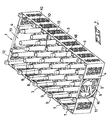
- the irrigation and/or drainage box 1 which is illustrated in the drawing, preferably consists of plastic and is made by injection-moulding, comprises a base 2, long side walls 3 and short side walls 4.
- the side walls 3, 4 are substantially perpendicular to the base 2 and are integrally connected thereto.
- the box 1 is open on the side which lies opposite the base.
- the base 2 and the side walls 3, 4 are provided with perforations or openings 5 and 6, respectively, which openings may have many different forms. These perforations or openings 5, 6 serve to allow water to pass through.
- the box 1 is furthermore provided with columns 7, 8 which extend substantially vertically from the base 2 towards the open side of the box, the columns 7 adjoining the side walls 3, 4 and being integral therewith, while the columns 8 stand free in the box 1.
- the columns 7 which are integral with the side walls 3, 4 are of planar design at least on the side which adjoins the side walls 3, 4. In the embodiment of the box 1 illustrated, this planar side lies in the same plane as the outer side of the side wall 3, 4 in question, and the columns 7 in question are preferably substantially square in cross section.
- the columns 8 standing inside the box are preferably round in cross section, since this is advantageous from the manufacturing technology viewpoint.
- the base 2 and the side walls 3, 4, as can also be seen in the drawing, are preferably of substantially planar design and free from projections on the outer side of the box.
- the box 1 according to the invention is designed in such a manner that two same boxes can be placed with the open sides towards one another and can be connected to one another without the need for further accessories, producing a unit as shown in Fig. 5.
- At least some of the columns 7, 8, usually half of the columns 7, 8, are provided, on the open side of the box, with first connection parts, and other columns 7, 8, usually the other half of the columns 7, 8, are provided, on the open side of the box, with second connection parts.
- first connection parts of one box are able to interact with the second connection parts of the other box, thus forming a connection between the two boxes.
- the first connection parts are formed by projections 9 which lie at the free end of the columns 7, 8 in question and form an extension of these columns
- the second connection parts are formed by cavities 10 which are formed in the free end section of the columns 7, 8 in question.
- the distribution of the projections 9 and the cavities 10 is such that when two boxes 1 are placed with the open sides towards one another, projections 9 on columns 7, 8 of one box fit into cavities 10 in columns 7, 8 of the other box, thus forming the connection between the two boxes.
- connection between a first connection part (projection 9) and second connection part (cavity 10) is a click-fit or clamp-fit connection.
- openings 11 through which water can run into or out of the columns 7, 8 are formed in the projections 9. Furthermore, the openings 11 are advantageous when moulding the columns, since they provide the option of supporting a core which forms the inside of the column 7, 8, during injection-moulding of a box 1 in an injection mould, on a mould part which forms the outside of the column 7, 8.
- the top side of the columns 7, 8 extends approximately as far as the plane which is defined by the edges 12 of the side walls 3, 4 and the projections 9 project beyond this plane.
- the side walls it is preferable for at least one of the side walls to be provided with a preferably round opening 13.
- the two short side walls 4 are provided with such an opening 13.
- the opening 13 is provided with a grate 14, which can easily be removed.
- a connection pipe 15 (cf. Fig. 6) can be fitted into the opening 13, preferably after the grate 14 has been removed.
- a connection pipe can then again be fitted into this half pipe socket.
- the connection between the connection pipe 15 and the box 1 does not have to be leaktight.
- the connection using a half pipe socket prevents the connection pipe from slipping out of the opening 13 in the event of any subsidence.
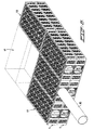
- two same boxes 1 can be placed with the open sides towards one another, thus forming a unit 17 (cf. Fig. 5) which is delimited by the two bases 2 and side walls 3, 4 and which is able to leave an underground space open.
- Covering units of this nature with filter cloth prevents soil particles from penetrating into and contaminating the underground space and ultimately limiting the capacity of the units.
- the ratio between the length and the width is 2:1.
- the columns 7, 8 are preferably provided with connection parts 9, 10 and positioned in such a manner that two boxes 1 can be placed against one another with their longitudinal axes parallel to one another so that they completely overlap, but also with their longitudinal axes perpendicular to one another.
- two boxes form a separate unit which is delimited by the bases and side walls, as illustrated in Fig. 5.
- the dimensions (length x width x height) of a box are 100 x 50 x 23.4 cm.
- the openings 13 in the side walls 10 have a diameter of approx. 18 cm.
- a plurality of units 17 formed by two boxes 1 which have been placed with the open sides towards one another can be placed on top of and/or next to one another and coupled together, so as to form larger systems.
- Fig. 6 shows such a system with six units 17 (twelve boxes 1).
- a connection pipe 15 is connected to one of the boxes.
- two units 17 which are indicated by dashed lines are positioned transversely with respect to the other units 17.
- Connection parts (not shown) can be used to couple together the boxes.
- the connection parts may be simple loose clamps, but may also be integral connection parts formed on the boxes themselves.
- the base 2 which is planar on the outer side, is provided, inside the box, with a relatively large number of columns 7, 8 and ribs 18, in order to make the boxes able to withstand any loads on the ground which arise.
Claims (15)
- Irrigations- und/oder Drainagekasten (1), mit einer Basis (2), die mit Perforationen (5) versehen ist, und Seitenwänden (3,4), die mit Perforationen (6) versehen und einstückig mit der Basis verbunden sind, wobei der Kasten an der Seite offen ist, die der Basis gegenüberliegt, und der Kasten an der offenen Se te derart ausgebildet ist, daß zwei gleiche Kästen (1) mit den offen Seiten gegeneinandergesetzt und miteinander ohne das Erfordernis weiteren Zubehörs verbunden werden können, dadurch gekennzeichnet, daß die Seitenwände (3,4) im wesentlichen senkrecht zur Basis (2) stehen, daß der Kasten (1) Säulen (7,8) aufweist, die sich im wesentlichen senkrecht von der Basis (2) zu der offenen Seite erstrecken, und daß zumindest einige der Säulen (7,8) an der offenen Seite des Kasten mit ersten Verbindungsteilen (9) und andere Säulen (7,8) an der offenen Seite des Kasten mit zweiten Verbindungsteilen (10) versehen sind, derart, daß, wenn zwei gleiche Kästen nach der Erfindung mit den offenen Seiten gegeneinandergesetzt werden, die ersten Verbindungsteile (9) eines der beiden gleichen Kästen in der Lage sind, mit den zweiten Verbindungsteilen (10) des anderen der beiden gleichen Kästen zusammenzuwirken, um eine Verbindung zwischen den beiden gleichen Kästen zu bilden.
- Irrigations- und/oder Drainagekasten nach Anspruch 1, dadurch gekennzeichnet, daß die ersten Verbindungsteile von Vorsprüngen (9) gebildet sind, die am freien Ende der fraglichen Säulen (7,8) liegen und eine Verlängerung dieser Säulen bilden, und die zweiten Verbindungsteile von Hohlräumen (10) gebildet sind, die im freien Endabschnitt der fraglichen Säulen (7,8) gebildet sind, derart, daß, wenn zwei gleiche Kästen mit den offenen Seiten gegeneinandergesetzt werden, Vorsprünge (9) an Säulen eines der beiden Kästen in Hohlräume (10) in Säulen des anderen der beiden Kästen hineinpassen.
- Irrigations- und/oder Drainagekasten nach Anspruch 2, dadurch gekennzeichnet, daß die Verbindung zwischen dem ersten (9) und dem zweiten Verbindungsteil (10) eine Schnapp- oder Klemmverbindung ist.
- Irrigations- und/oder Drainagekasten nach einem der Ansprüche 1 bis 3, dadurch gekennzeichnet, daß der Kasten (1) mit Säulen (7) versehen ist, die an die Seitenwände (3,4) angrenzen, mit diesen einstückig sind und eine ebenflächige Ausbildung zumindest an der Seite aufweisen, die an die Seitenwände angrenzt.
- Irrigations- und/oder Drainagekasten nach Anspruch 4, dadurch gekennzeichnet, daß die ebenflächige Seite der Säule (7), die mit einer Seitenwand (3,4) einstückig ist, in der gleichen Ebene liegt wie die Außenseite der fraglichen Seitenwand.
- Irrigations- und/oder Drainagekasten nach einem der Ansprüche 1 bis 5, dadurch gekennzeichnet, daß die Basis (2) und die Seitenwände (3,4) des Kastens (1) eine im wesentlichen ebenflächige Ausbildung auf der Außenseite des Kastens aufweisen.
- Irrigations- und/oder Drainagekasten nach einem der Ansprüche 1 bis 6, dadurch gekennzeichnet, daß Säulen (8), die nicht an die Seitenwände (3,4) angrenzen, im Querschnitt im wesentlichen rund sind.
- Irrigations- und/oder Drainagekasten nach einem der Ansprüche 1 bis 7, dadurch gekennzeichnet, daß zumindest eine der Seitenwände (4) mit einer Öffnung (13) versehen ist, in die ein Rohrteil eingesetzt werden kann.
- Irrigations- und/oder Drainagekasten nach Anspruch 8, dadurch gekennzeichnet, daß die Öffnung (13) mit einem Gitter (14) versehen ist.
- Irrigations- und/oder Drainagekasten nach Anspruch 9, dadurch gekennzeichnet, daß das Gitter (14) abnehmbar ist.
- Irrigations- und/oder Drainagekasten nach einem der Ansprüche 8 bis 10, dadurch gekennzeichnet, daß zwei Seitenwände (4), die einander gegenüberliegen, mit einer Öffnung (13) versehen sind.
- Irrigations- und/oder Drainagekasten nach einem der Ansprüche 1 bis 11, dadurch gekennzeichnet, daß das Verhältnis zwischen Länge und Breite des Kastens (1) 2:1 beträgt.
- Irrigations- und/oder Drainagekasten nach Anspruch 12, dadurch gekennzeichnet, daß die ersten und zweiten Verbindungsteile (9,10) derart angeordnet sind, daß zwei gleiche Kästen (1) mit ihren offenen Seiten gegeneinandergesetzt und miteinander verbunden werden können, mit ihren Längsachsen parallel zueinander, so daß sie einander vollständig übergreifen, jedoch auch mit ihren Längsachsen senkrecht zueinander.
- Irrigations- und/oder Drainageeinheit, mit zwei gleichen Kästen (1) nach einem oder mehreren der Ansprüche 1 bis 13, die mit den offen Seiten gegeneinandergesetzt und miteinander verbunden sind.
- Irrigations- und/oder Drainagesystem, mit einer Mehrzahl von Kästen (1) nach einem oder mehreren der Ansprüche 1 bis 13.
Priority Applications (1)
| Application Number | Priority Date | Filing Date | Title |
|---|---|---|---|
| DE29924050U DE29924050U1 (de) | 1998-03-18 | 1999-03-09 | Bewässerungs- und/oder Drainagekasten |
Applications Claiming Priority (2)
| Application Number | Priority Date | Filing Date | Title |
|---|---|---|---|
| NL1008627A NL1008627C2 (nl) | 1998-03-18 | 1998-03-18 | Irrigatie- en/of drainagebak. |
| NL1008627 | 1998-03-18 |
Publications (2)
| Publication Number | Publication Date |
|---|---|
| EP0943737A1 EP0943737A1 (de) | 1999-09-22 |
| EP0943737B1 true EP0943737B1 (de) | 2003-06-04 |
Family
ID=19766764
Family Applications (1)
| Application Number | Title | Priority Date | Filing Date |
|---|---|---|---|
| EP99200704A Expired - Lifetime EP0943737B1 (de) | 1998-03-18 | 1999-03-09 | Kasten zur Irrigation und Drainage |
Country Status (5)
| Country | Link |
|---|---|
| EP (1) | EP0943737B1 (de) |
| AT (1) | ATE242366T1 (de) |
| DE (1) | DE69908459T2 (de) |
| DK (1) | DK0943737T3 (de) |
| NL (1) | NL1008627C2 (de) |
Cited By (6)
| Publication number | Priority date | Publication date | Assignee | Title |
|---|---|---|---|---|
| DE102009044412A1 (de) | 2009-10-05 | 2011-04-07 | Aco Severin Ahlmann Gmbh & Co. Kg | Rigolenkörper |
| DE102010028607A1 (de) * | 2010-05-05 | 2011-11-10 | Fränkische Rohrwerke Gebr. Kirchner Gmbh & Co. Kg | Raumsparende Anordnung von Rigolenkomponenten und diese ermöglichende Rigolenkomponente |
| AU2007329188B2 (en) * | 2006-12-06 | 2013-03-21 | Jack Mckenzie Droomer | Support structure |
| EP2592194A1 (de) | 2011-11-09 | 2013-05-15 | FRÄNKISCHE ROHRWERKE GEBR. KIRCHNER GmbH & Co KG | Rigoleneinheit und aus derartigen Rigoleneinheiten gebildete Transporteinheit |
| EP2169127B1 (de) | 2004-06-18 | 2015-11-25 | Wavin B.V. | Versickerungsblock |
| WO2023150257A1 (en) * | 2022-02-03 | 2023-08-10 | Ohio University | Stress-reducing profile for modular storm drainage management systems |
Families Citing this family (31)
| Publication number | Priority date | Publication date | Assignee | Title |
|---|---|---|---|---|
| AUPQ349099A0 (en) * | 1999-10-18 | 1999-11-11 | Urriola, Humberto | Modular drainage channels |
| AUPQ514100A0 (en) * | 2000-01-17 | 2000-02-10 | Lee, Alan Sian Ghee | Interconnectable structural module |
| PT1311727E (pt) * | 2000-08-17 | 2008-09-10 | Permavoid Ltd | Pavimento com módulo estrutural |
| DE10055323C1 (de) * | 2000-11-08 | 2002-01-17 | Sendenhorst Kunststoffroehren | Dreidimensionale Struktur aus Gitterplatten |
| DE10055327C1 (de) | 2000-11-08 | 2002-01-24 | Sendenhorst Kunststoffroehren | Gitterplatte mit unterschiedlichen Strebenabständen |
| DE10123754A1 (de) * | 2001-05-16 | 2002-12-05 | Kirchner Fraenk Rohr | Rigolenanordnung sowie Rigolenbauteil zu dessen Aufbau |
| EP1416099B1 (de) * | 2002-10-31 | 2008-09-17 | Polypipe Civils Limited | Grundwasserdrainagesystem |
| DE20303343U1 (de) * | 2003-03-01 | 2003-06-12 | Hauraton Betonwaren | Versickerungssystem |
| GB0308587D0 (en) * | 2003-04-14 | 2003-05-21 | Polypipe Civils Ltd | Apparatus and system for through flow of a fluid |
| DE20321648U1 (de) * | 2003-10-17 | 2008-11-13 | Funke Kunststoffe Gmbh | Drainage-Tank mit Spülrohr |
| DE102005006202A1 (de) * | 2005-02-11 | 2006-08-24 | Rehau Ag + Co. | Versickerungsvorrichtung |
| CA2576600C (en) * | 2006-02-08 | 2010-05-11 | Brentwood Industries, Inc. | Water drain tank or channel module |
| US20070227094A1 (en) * | 2006-03-14 | 2007-10-04 | Larach Oscar | Modular raintank |
| US7677835B2 (en) * | 2006-03-14 | 2010-03-16 | Larach Oscar | Drainage cell modular raintank and water storage system |
| GB2440398A (en) * | 2006-07-25 | 2008-01-30 | Polypipe Civils Ltd | Ground water system |
| FR2929630B1 (fr) | 2008-04-02 | 2011-11-25 | Aliaxis Participations | Bac de retention d'eau permettant de constituer par assemblage de bacs un dispositif de retention d'eau enfoui dans le sol |
| GB2475551B (en) * | 2009-11-23 | 2012-12-26 | Polypipe Civils Ltd | Drainage cell |
| EP2682534A1 (de) * | 2012-07-04 | 2014-01-08 | Wavin B.V. | Bewässerungskasten, Entwässerungskasten und ein Satz aus zwei dieser Kästen |
| EP2687642A1 (de) * | 2012-07-17 | 2014-01-22 | Sell Kunststoffen B.V. | Bewässerungs- und/oder Abflussanordnung |
| CN203938946U (zh) | 2013-04-04 | 2014-11-12 | 斯特拉塔创新有限公司 | 模块化单元和位于承重部件下方的矩阵 |
| NL1040956B1 (en) | 2014-09-19 | 2016-09-29 | Wavin Bv | A plastic infiltration unit, a system comprising a plurality of plastic infiltration units, a method of manufacturing an injection molded plastic pillar for an infiltration unit, a plastic base plate for use with a plastic infiltration unit, and a plastic infiltration system for deployment underground comprising a plastic infiltration unit and a plastic base plate. |
| NL1040958B1 (en) | 2014-09-19 | 2016-09-29 | Wavin Bv | A plastic infiltration unit, a system comprising a plurality of plastic infiltration units. |
| US9775303B2 (en) | 2015-04-10 | 2017-10-03 | Deeproot Green Infrastructure, Llc | More efficient structural cell for facilitating tree root growth |
| CN105317076B (zh) * | 2015-10-22 | 2017-12-08 | 上海江建实业有限公司 | 一种雨水收集存储系统及其施工方法 |
| WO2021229403A1 (en) * | 2020-05-13 | 2021-11-18 | Pillay Morgan Rungen | Underground tank system and method of manufacturing an underground tank system |
| DE102020005908A1 (de) | 2020-09-28 | 2022-03-31 | Optigrün international AG | Dachaufständerungssystem, dachaufständerung und verfahren zum aufbau einer dachaufständerung |
| DE202021106956U1 (de) | 2021-12-21 | 2023-03-22 | REHAU Industries SE & Co. KG | Rigolenanordnung |
| DE202022107153U1 (de) | 2021-12-21 | 2023-03-24 | REHAU Industries SE & Co. KG | Rigolenanordnung |
| DE202021106945U1 (de) | 2021-12-21 | 2023-03-22 | REHAU Industries SE & Co. KG | Rigolenanordnung |
| DE202021106944U1 (de) | 2021-12-21 | 2023-03-23 | REHAU Industries SE & Co. KG | Rigolenanordnung |
| DE202022107143U1 (de) | 2021-12-21 | 2023-03-24 | REHAU Industries SE & Co. KG | Bodengitteranordnung |
Citations (1)
| Publication number | Priority date | Publication date | Assignee | Title |
|---|---|---|---|---|
| JPH0426648A (ja) * | 1990-05-18 | 1992-01-29 | Asahi Glass Co Ltd | フッ素化ベンズアルデヒド類の製造方法 |
Family Cites Families (3)
| Publication number | Priority date | Publication date | Assignee | Title |
|---|---|---|---|---|
| DE2521374A1 (de) * | 1975-05-14 | 1976-12-02 | Rosemeier Kg | Bauelement fuer die draenage, bewaesserung, belueftung und beheizung von flaechen im erd-, grund-, wasser- und heizungsbau |
| JPH083443Y2 (ja) * | 1992-04-24 | 1996-01-31 | 有限会社クリーン・アップ・システム | 排水・保水装置 |
| FR2744154B1 (fr) | 1996-01-30 | 1998-04-30 | Boissie Chantal | Caisson et systeme isolant et de drainage de sol |
-
1998
- 1998-03-18 NL NL1008627A patent/NL1008627C2/nl not_active IP Right Cessation
-
1999
- 1999-03-09 DE DE69908459T patent/DE69908459T2/de not_active Expired - Lifetime
- 1999-03-09 AT AT99200704T patent/ATE242366T1/de not_active IP Right Cessation
- 1999-03-09 DK DK99200704T patent/DK0943737T3/da active
- 1999-03-09 EP EP99200704A patent/EP0943737B1/de not_active Expired - Lifetime
Patent Citations (1)
| Publication number | Priority date | Publication date | Assignee | Title |
|---|---|---|---|---|
| JPH0426648A (ja) * | 1990-05-18 | 1992-01-29 | Asahi Glass Co Ltd | フッ素化ベンズアルデヒド類の製造方法 |
Cited By (10)
| Publication number | Priority date | Publication date | Assignee | Title |
|---|---|---|---|---|
| EP2169127B1 (de) | 2004-06-18 | 2015-11-25 | Wavin B.V. | Versickerungsblock |
| AU2007329188B2 (en) * | 2006-12-06 | 2013-03-21 | Jack Mckenzie Droomer | Support structure |
| DE102009044412A1 (de) | 2009-10-05 | 2011-04-07 | Aco Severin Ahlmann Gmbh & Co. Kg | Rigolenkörper |
| WO2011042415A1 (de) | 2009-10-05 | 2011-04-14 | Aco Severin Ahlmann Gmbh & Co. Kg | Rigolenkörper |
| DE202010018411U1 (de) | 2009-10-05 | 2016-05-30 | ACO Severin Ahlmann GmbH & Co Kommanditgesellschaft | Rigolenkörper |
| DE102010028607A1 (de) * | 2010-05-05 | 2011-11-10 | Fränkische Rohrwerke Gebr. Kirchner Gmbh & Co. Kg | Raumsparende Anordnung von Rigolenkomponenten und diese ermöglichende Rigolenkomponente |
| EP2592194A1 (de) | 2011-11-09 | 2013-05-15 | FRÄNKISCHE ROHRWERKE GEBR. KIRCHNER GmbH & Co KG | Rigoleneinheit und aus derartigen Rigoleneinheiten gebildete Transporteinheit |
| DE102011086016A1 (de) | 2011-11-09 | 2013-05-16 | Fränkische Rohrwerke Gebr. Kirchner Gmbh & Co. Kg | Rigoleneinheit und aus derartigen Rigoleneinheiten gebildete Transporteinheit |
| WO2013068541A1 (de) | 2011-11-09 | 2013-05-16 | Fränkische Rohrwerke Gebr. Kirchner Gmbh & Co. Kg | Rigoleneinheit und aus derartigen rigoleneinheiten gebildete transporteinheit |
| WO2023150257A1 (en) * | 2022-02-03 | 2023-08-10 | Ohio University | Stress-reducing profile for modular storm drainage management systems |
Also Published As
| Publication number | Publication date |
|---|---|
| DK0943737T3 (da) | 2003-06-23 |
| EP0943737A1 (de) | 1999-09-22 |
| NL1008627C2 (nl) | 1999-09-21 |
| ATE242366T1 (de) | 2003-06-15 |
| DE69908459D1 (de) | 2003-07-10 |
| DE69908459T2 (de) | 2004-05-06 |
Similar Documents
| Publication | Publication Date | Title |
|---|---|---|
| EP0943737B1 (de) | Kasten zur Irrigation und Drainage | |
| US7712997B2 (en) | Infiltration block | |
| CA2776567C (en) | Drainage body | |
| JPH0650006B2 (ja) | コンクリート壁型を形成するブロック | |
| JP2006214103A (ja) | 桝体、及び、これを用いた雨水等貯留浸透施設 | |
| CN109392519B (zh) | 拼接式植物种植箱 | |
| JP3655578B2 (ja) | 擁壁ブロック | |
| US5911540A (en) | Subterranean liquid distribution apparatus | |
| US6712554B1 (en) | Modular drainage unit | |
| KR102561028B1 (ko) | 결합 및 방수 성능이 탁월한 세대단자함 | |
| KR200230439Y1 (ko) | 조경용 화단 조립체 | |
| KR200439332Y1 (ko) | 배수 트렌치 유닛 | |
| JP3738558B2 (ja) | 植樹擁壁ユニット及び植樹擁壁の構築方法 | |
| KR200165365Y1 (ko) | 배수트랩 | |
| KR200439333Y1 (ko) | 배수 트렌치 유닛 | |
| DK2169127T3 (en) | infiltration block | |
| JPS636324Y2 (de) | ||
| JP2004275009A (ja) | 植栽用パレット | |
| CA1183696A (en) | Arrangement relating to a drainage pipe | |
| KR200241626Y1 (ko) | 보도블록 | |
| JPH0567638U (ja) | 街路灯用基礎 | |
| JPH03103407U (de) | ||
| CA2102057A1 (en) | Interlocking block planter device | |
| JPH07229196A (ja) | 排水桝の構造 | |
| IT9020718U1 (it) | Elemento prefabbricato in calcestruzzo per la realizzazione di fiorier e componibili e fioriere realizzate con esso |
Legal Events
| Date | Code | Title | Description |
|---|---|---|---|
| PUAI | Public reference made under article 153(3) epc to a published international application that has entered the european phase |
Free format text: ORIGINAL CODE: 0009012 |
|
| AK | Designated contracting states |
Kind code of ref document: A1 Designated state(s): AT BE CH CY DE DK ES FI FR GB GR IE IT LI LU MC NL PT SE |
|
| AX | Request for extension of the european patent |
Free format text: AL;LT;LV;MK;RO;SI |
|
| 17P | Request for examination filed |
Effective date: 20000131 |
|
| AKX | Designation fees paid |
Free format text: AT BE CH CY DE DK ES FI FR GB GR IE IT LI LU MC NL PT SE |
|
| AXX | Extension fees paid |
Free format text: AL PAYMENT 20000131;LT PAYMENT 20000131;LV PAYMENT 20000131;MK PAYMENT 20000131;RO PAYMENT 20000131;SI PAYMENT 20000131 |
|
| 17Q | First examination report despatched |
Effective date: 20020529 |
|
| GRAH | Despatch of communication of intention to grant a patent |
Free format text: ORIGINAL CODE: EPIDOS IGRA |
|
| GRAH | Despatch of communication of intention to grant a patent |
Free format text: ORIGINAL CODE: EPIDOS IGRA |
|
| GRAA | (expected) grant |
Free format text: ORIGINAL CODE: 0009210 |
|
| AK | Designated contracting states |
Designated state(s): AT BE CH CY DE DK ES FI FR GB GR IE IT LI LU MC NL PT SE |
|
| AX | Request for extension of the european patent |
Extension state: AL LT LV MK RO SI |
|
| PG25 | Lapsed in a contracting state [announced via postgrant information from national office to epo] |
Ref country code: LI Free format text: LAPSE BECAUSE OF FAILURE TO SUBMIT A TRANSLATION OF THE DESCRIPTION OR TO PAY THE FEE WITHIN THE PRESCRIBED TIME-LIMIT Effective date: 20030604 Ref country code: IT Free format text: LAPSE BECAUSE OF FAILURE TO SUBMIT A TRANSLATION OF THE DESCRIPTION OR TO PAY THE FEE WITHIN THE PRESCRIBED TIME-LIMIT;WARNING: LAPSES OF ITALIAN PATENTS WITH EFFECTIVE DATE BEFORE 2007 MAY HAVE OCCURRED AT ANY TIME BEFORE 2007. THE CORRECT EFFECTIVE DATE MAY BE DIFFERENT FROM THE ONE RECORDED. Effective date: 20030604 Ref country code: FI Free format text: LAPSE BECAUSE OF FAILURE TO SUBMIT A TRANSLATION OF THE DESCRIPTION OR TO PAY THE FEE WITHIN THE PRESCRIBED TIME-LIMIT Effective date: 20030604 Ref country code: CY Free format text: LAPSE BECAUSE OF FAILURE TO SUBMIT A TRANSLATION OF THE DESCRIPTION OR TO PAY THE FEE WITHIN THE PRESCRIBED TIME-LIMIT Effective date: 20030604 Ref country code: CH Free format text: LAPSE BECAUSE OF FAILURE TO SUBMIT A TRANSLATION OF THE DESCRIPTION OR TO PAY THE FEE WITHIN THE PRESCRIBED TIME-LIMIT Effective date: 20030604 Ref country code: BE Free format text: LAPSE BECAUSE OF FAILURE TO SUBMIT A TRANSLATION OF THE DESCRIPTION OR TO PAY THE FEE WITHIN THE PRESCRIBED TIME-LIMIT Effective date: 20030604 Ref country code: AT Free format text: LAPSE BECAUSE OF FAILURE TO SUBMIT A TRANSLATION OF THE DESCRIPTION OR TO PAY THE FEE WITHIN THE PRESCRIBED TIME-LIMIT Effective date: 20030604 |
|
| REG | Reference to a national code |
Ref country code: GB Ref legal event code: FG4D |
|
| REG | Reference to a national code |
Ref country code: CH Ref legal event code: EP |
|
| REG | Reference to a national code |
Ref country code: DK Ref legal event code: T3 |
|
| REG | Reference to a national code |
Ref country code: IE Ref legal event code: FG4D |
|
| REF | Corresponds to: |
Ref document number: 69908459 Country of ref document: DE Date of ref document: 20030710 Kind code of ref document: P |
|
| PG25 | Lapsed in a contracting state [announced via postgrant information from national office to epo] |
Ref country code: SE Free format text: LAPSE BECAUSE OF FAILURE TO SUBMIT A TRANSLATION OF THE DESCRIPTION OR TO PAY THE FEE WITHIN THE PRESCRIBED TIME-LIMIT Effective date: 20030904 Ref country code: PT Free format text: LAPSE BECAUSE OF FAILURE TO SUBMIT A TRANSLATION OF THE DESCRIPTION OR TO PAY THE FEE WITHIN THE PRESCRIBED TIME-LIMIT Effective date: 20030904 Ref country code: GR Free format text: LAPSE BECAUSE OF FAILURE TO SUBMIT A TRANSLATION OF THE DESCRIPTION OR TO PAY THE FEE WITHIN THE PRESCRIBED TIME-LIMIT Effective date: 20030904 |
|
| PG25 | Lapsed in a contracting state [announced via postgrant information from national office to epo] |
Ref country code: ES Free format text: LAPSE BECAUSE OF FAILURE TO SUBMIT A TRANSLATION OF THE DESCRIPTION OR TO PAY THE FEE WITHIN THE PRESCRIBED TIME-LIMIT Effective date: 20030915 |
|
| LTIE | Lt: invalidation of european patent or patent extension |
Effective date: 20030604 |
|
| REG | Reference to a national code |
Ref country code: CH Ref legal event code: PL |
|
| PG25 | Lapsed in a contracting state [announced via postgrant information from national office to epo] |
Ref country code: LU Free format text: LAPSE BECAUSE OF NON-PAYMENT OF DUE FEES Effective date: 20040309 Ref country code: IE Free format text: LAPSE BECAUSE OF NON-PAYMENT OF DUE FEES Effective date: 20040309 |
|
| PLBQ | Unpublished change to opponent data |
Free format text: ORIGINAL CODE: EPIDOS OPPO |
|
| PLBI | Opposition filed |
Free format text: ORIGINAL CODE: 0009260 |
|
| PG25 | Lapsed in a contracting state [announced via postgrant information from national office to epo] |
Ref country code: MC Free format text: LAPSE BECAUSE OF NON-PAYMENT OF DUE FEES Effective date: 20040331 |
|
| PLAX | Notice of opposition and request to file observation + time limit sent |
Free format text: ORIGINAL CODE: EPIDOSNOBS2 |
|
| ET | Fr: translation filed | ||
| 26 | Opposition filed |
Opponent name: OTTO GRAF GMBH KUNSTSTOFFERZEUGNISSE Effective date: 20040303 |
|
| NLR1 | Nl: opposition has been filed with the epo |
Opponent name: OTTO GRAF GMBH KUNSTSTOFFERZEUGNISSE |
|
| PLBB | Reply of patent proprietor to notice(s) of opposition received |
Free format text: ORIGINAL CODE: EPIDOSNOBS3 |
|
| REG | Reference to a national code |
Ref country code: IE Ref legal event code: MM4A |
|
| PLCK | Communication despatched that opposition was rejected |
Free format text: ORIGINAL CODE: EPIDOSNREJ1 |
|
| APBP | Date of receipt of notice of appeal recorded |
Free format text: ORIGINAL CODE: EPIDOSNNOA2O |
|
| APAH | Appeal reference modified |
Free format text: ORIGINAL CODE: EPIDOSCREFNO |
|
| APBQ | Date of receipt of statement of grounds of appeal recorded |
Free format text: ORIGINAL CODE: EPIDOSNNOA3O |
|
| PGFP | Annual fee paid to national office [announced via postgrant information from national office to epo] |
Ref country code: DK Payment date: 20090324 Year of fee payment: 11 |
|
| APBU | Appeal procedure closed |
Free format text: ORIGINAL CODE: EPIDOSNNOA9O |
|
| PLBN | Opposition rejected |
Free format text: ORIGINAL CODE: 0009273 |
|
| STAA | Information on the status of an ep patent application or granted ep patent |
Free format text: STATUS: OPPOSITION REJECTED |
|
| 27O | Opposition rejected |
Effective date: 20091022 |
|
| NLR2 | Nl: decision of opposition |
Effective date: 20091022 |
|
| REG | Reference to a national code |
Ref country code: DK Ref legal event code: EBP |
|
| PG25 | Lapsed in a contracting state [announced via postgrant information from national office to epo] |
Ref country code: DK Free format text: LAPSE BECAUSE OF NON-PAYMENT OF DUE FEES Effective date: 20100331 |
|
| PGFP | Annual fee paid to national office [announced via postgrant information from national office to epo] |
Ref country code: FR Payment date: 20120403 Year of fee payment: 14 |
|
| REG | Reference to a national code |
Ref country code: FR Ref legal event code: ST Effective date: 20131129 |
|
| PG25 | Lapsed in a contracting state [announced via postgrant information from national office to epo] |
Ref country code: FR Free format text: LAPSE BECAUSE OF NON-PAYMENT OF DUE FEES Effective date: 20130402 |
|
| PGFP | Annual fee paid to national office [announced via postgrant information from national office to epo] |
Ref country code: GB Payment date: 20180228 Year of fee payment: 20 Ref country code: NL Payment date: 20180321 Year of fee payment: 20 |
|
| PGFP | Annual fee paid to national office [announced via postgrant information from national office to epo] |
Ref country code: DE Payment date: 20180323 Year of fee payment: 20 |
|
| REG | Reference to a national code |
Ref country code: DE Ref legal event code: R071 Ref document number: 69908459 Country of ref document: DE |
|
| REG | Reference to a national code |
Ref country code: NL Ref legal event code: MK Effective date: 20190308 |
|
| REG | Reference to a national code |
Ref country code: GB Ref legal event code: PE20 Expiry date: 20190308 |
|
| PG25 | Lapsed in a contracting state [announced via postgrant information from national office to epo] |
Ref country code: GB Free format text: LAPSE BECAUSE OF EXPIRATION OF PROTECTION Effective date: 20190308 |