EP0942246A2 - Procédé et appareil pour la séparation de l'air - Google Patents
Procédé et appareil pour la séparation de l'air Download PDFInfo
- Publication number
- EP0942246A2 EP0942246A2 EP19980113198 EP98113198A EP0942246A2 EP 0942246 A2 EP0942246 A2 EP 0942246A2 EP 19980113198 EP19980113198 EP 19980113198 EP 98113198 A EP98113198 A EP 98113198A EP 0942246 A2 EP0942246 A2 EP 0942246A2
- Authority
- EP
- European Patent Office
- Prior art keywords
- return line
- column
- heat exchanger
- fraction
- condensate
- Prior art date
- Legal status (The legal status is an assumption and is not a legal conclusion. Google has not performed a legal analysis and makes no representation as to the accuracy of the status listed.)
- Withdrawn
Links
Images

Classifications
-
- F—MECHANICAL ENGINEERING; LIGHTING; HEATING; WEAPONS; BLASTING
- F25—REFRIGERATION OR COOLING; COMBINED HEATING AND REFRIGERATION SYSTEMS; HEAT PUMP SYSTEMS; MANUFACTURE OR STORAGE OF ICE; LIQUEFACTION SOLIDIFICATION OF GASES
- F25J—LIQUEFACTION, SOLIDIFICATION OR SEPARATION OF GASES OR GASEOUS OR LIQUEFIED GASEOUS MIXTURES BY PRESSURE AND COLD TREATMENT OR BY BRINGING THEM INTO THE SUPERCRITICAL STATE
- F25J3/00—Processes or apparatus for separating the constituents of gaseous or liquefied gaseous mixtures involving the use of liquefaction or solidification
- F25J3/02—Processes or apparatus for separating the constituents of gaseous or liquefied gaseous mixtures involving the use of liquefaction or solidification by rectification, i.e. by continuous interchange of heat and material between a vapour stream and a liquid stream
- F25J3/04—Processes or apparatus for separating the constituents of gaseous or liquefied gaseous mixtures involving the use of liquefaction or solidification by rectification, i.e. by continuous interchange of heat and material between a vapour stream and a liquid stream for air
- F25J3/04763—Start-up or control of the process; Details of the apparatus used
- F25J3/04769—Operation, control and regulation of the process; Instrumentation within the process
- F25J3/04793—Rectification, e.g. columns; Reboiler-condenser
- F25J3/048—Argon recovery
- F25J3/04806—High purity argon purification
-
- F—MECHANICAL ENGINEERING; LIGHTING; HEATING; WEAPONS; BLASTING
- F25—REFRIGERATION OR COOLING; COMBINED HEATING AND REFRIGERATION SYSTEMS; HEAT PUMP SYSTEMS; MANUFACTURE OR STORAGE OF ICE; LIQUEFACTION SOLIDIFICATION OF GASES
- F25J—LIQUEFACTION, SOLIDIFICATION OR SEPARATION OF GASES OR GASEOUS OR LIQUEFIED GASEOUS MIXTURES BY PRESSURE AND COLD TREATMENT OR BY BRINGING THEM INTO THE SUPERCRITICAL STATE
- F25J3/00—Processes or apparatus for separating the constituents of gaseous or liquefied gaseous mixtures involving the use of liquefaction or solidification
- F25J3/02—Processes or apparatus for separating the constituents of gaseous or liquefied gaseous mixtures involving the use of liquefaction or solidification by rectification, i.e. by continuous interchange of heat and material between a vapour stream and a liquid stream
- F25J3/04—Processes or apparatus for separating the constituents of gaseous or liquefied gaseous mixtures involving the use of liquefaction or solidification by rectification, i.e. by continuous interchange of heat and material between a vapour stream and a liquid stream for air
- F25J3/04642—Recovering noble gases from air
- F25J3/04648—Recovering noble gases from air argon
- F25J3/04721—Producing pure argon, e.g. recovered from a crude argon column
- F25J3/04727—Producing pure argon, e.g. recovered from a crude argon column using an auxiliary pure argon column for nitrogen rejection
Definitions
- the invention relates to a method for decomposing a gas mixture Low-temperature rectification, in which at the top of a distillation column volatile head fraction is obtained, at least part of the head fraction a heat exchanger is conducted in the heat exchanger in indirect Heat exchange with a cooling medium is at least partially liquefied and that the resulting condensate is fed via a return line to the distillation column becomes. Furthermore, the invention relates to a device for disassembling a Gas mixture by low temperature rectification with at least one Distillation column and a heat exchanger, the heat exchanger via a Inlet for steam and a return line for condensate with the upper part of the Distillation column is connected.
- the Feed air is first broken down into a double column, with argon in the middle enriches the low pressure column. This area becomes a gas fraction taken, which consists essentially of oxygen and argon, and for further Rectification fed to a crude argon column. In the crude argon column it will Raw argon freed from oxygen and then in a for nitrogen removal Pure argon column headed.
- the Heat exchanger which serves as a condenser for the pure argon column, not directly to the Head of the pure argon column, but spaced from the pure argon column to provide.
- the gaseous top fraction of the pure argon column is over a supply line into the heat exchanger and the condensate via a The return line is returned to the pure argon column.
- the object of the present invention is therefore to provide a method and an apparatus for to improve the kind mentioned in the introduction so that the rectification process in the distillation column even with changes in the quantity of the heat exchanger amount of gas supplied is essentially stable.
- This object is achieved in that at least part of the condensate in the Return line is dammed.
- the invention is based on the knowledge that due to the flow resistance and the storage capacity for liquids in the lines to and from Heat exchanger also minor changes in the supplied to the heat exchanger Amount of gas, such as that due to fluctuations in supply or pressure transferred to the amount of reflux liquid become.
- the resulting dead times are particularly long if the Flow speed is small and / or the line length is long. This Dead times mean that the reflux ratio, i.e. the The ratio of the return flow to the gas flow fluctuates, so that deviations from the optimal operating conditions of the distillation column.
- the accumulation of condensate according to the invention does not take place in a specially for this provided storage container, but in the already existing return line.
- the term return line is understood to mean a line which at the beginning described method is mandatory, the size and diameter in are usually adapted to the turnover of the heat exchanger and their length is usually much larger than their diameter.
- the amount of from the return line to the distillation column conducted condensate depending on the amount of in the return line dammed condensate regulated.
- the Return i.e. a valve may be arranged immediately upstream of the distillation column. This receives its control signal, for example, from a fill level controller, which also is connected to a sensor that determines the level in the return line.
- the top fraction in the heat exchanger is indirect Liquefied heat exchange with an oxygen-containing fraction.
- another fraction in indirect is advantageous Heat exchange with the cooling medium cooled or at least partially liquefied. It is particularly advantageous if the further fraction in the Cooled heat exchanger in indirect heat exchange with the cooling medium or is at least partially liquefied.
- the invention are the beginning Disadvantages described with regard to dead times and time delays, which so far at Heat exchangers or condenser evaporators that did not immediately occur the distillation column are avoided. It is therefore particularly useful a common heat exchanger for two fractions to be condensed, for example the top fraction of the crude argon column and the top fraction of the Pure argon column to be provided.
- a heat exchanger with separate passages for the both fractions to be condensed and the cooling medium is less expensive than two separate heat exchangers.
- the invention is particularly advantageous in cases in which at least a part the top fraction is withdrawn in gaseous form.
- the amount of gas withdrawn can be in Dependency of the pressure or the flow can be set. Preferably becomes at least a part of the head fraction emerging from the heat exchanger withdrawn in gaseous form. It is particularly advantageous if this part is dependent is subtracted from the pressure at the top of the distillation column. At this The procedure can be controlled by controlling the top pressure of the distillation column Rectification in the distillation column even with pressure and volume fluctuations be further improved.
- the invention is particularly suitable in processes in which an argon Enriched gas mixture disassembled in a pure argon column and at the top of the Pure argon column obtained a head fraction containing essentially nitrogen , at least part of the top fraction is passed to a heat exchanger in which Heat exchanger in indirect heat exchange with a cooling medium at least is partially liquefied and the resulting condensate via a return line is passed to the pure argon column, with at least part of the condensate in the Return line is dammed.
- the invention also relates to a device for Decomposition of a gas mixture by low temperature rectification with at least one Distillation column and a heat exchanger, the heat exchanger via a Inlet for steam and a return line for condensate with the upper part of the Distillation column is connected.
- a valve which is an actuating signal from a Level controller receives the one stored in the return line Liquid quantity measuring device is connected.
- the level controller is one that is stored in the return line Liquid quantity measuring device connected, which is preferably in the first 50%, particularly preferably in the first 25%, very particularly preferably in the first 10%, the return line, starting from the heat exchanger, located.
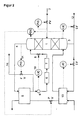
- argon is introduced via line 2 of a pure argon column 1 and supplied nitrogen gas mixture.
- this mixture in pure argon, which is drawn off at the bottom 3 of column 1, and a head fraction consisting essentially of nitrogen is broken down.
- the Bottom fraction is removed in part via line 12 as a pure argon product, partly in the evaporator 13 against liquid raw oxygen from the bottom of the not
- the pressure column shown evaporates and into the lower third of the pure argon column 1 initiated.
- the top fraction formed in column 1 is fed via line 4 to a Evaporator-condenser working heat exchanger 5 fed. In this Heat exchanger 5 becomes the top fraction against that from the heat exchanger 13 escaping, liquid raw oxygen at least partially condensed.
- From the heat exchanger 5 occurs essentially from nitrogen condensate and Residual gas existing two-phase mixture.
- the residual gas is via line 14 discharged into the atmosphere, regulating the amount of residual gas released via a flow controller 15.
- the condensate is fed back through the which consists of a first section 6 and a second section 7 passed to the pure argon column 1 and in the upper third of this column 1 as Returned liquid returned.
- the second section 7 is a U-tube formed so that the condensate collects in the lower arc of the U-tube 7 and thus prevents the escape of gas from the return line 7 into the pure argon column 1.
- the pressure allowed in the pure argon column 1 is upwards by that in the Crude argon column pressure of about 1.2 to 1.5 bar, because otherwise the supply of raw argon in the pure argon column 1 without aids it is possible.
- the pressure in the pure argon column 1 must be at least as high be as large as the atmospheric pressure, for example, residual gas via line 14 to be able to release the environment without drawing in false air. Because of In this narrow allowable pressure range, it is particularly important that the The reflux ratio in the pure argon column 1 is always at the optimum. this applies generally for all columns that are operated in a narrow pressure range.
- a valve 8 which is its control signal from a level controller 10 receives. This stands with one immediately after the Heat exchanger 5 arranged measuring point 9 in connection. With the measuring device 9 the liquid level in the return line 6, 7 is measured. Almost throughout Return line 6, 7 is accumulated condensate.
- the process scheme shown in FIG. 2 differs from that in FIG. 1 Scheme shown in that the amount of residual gas discharged to the atmosphere not as a function of a flow regulator 15, but via a pressure regulator 11 is set by the pressure at the top of the pure argon column 1. Through this pressure control instabilities of the rectification process in the pure argon column 1 are additional decreased.
Landscapes
- Engineering & Computer Science (AREA)
- Physics & Mathematics (AREA)
- Mechanical Engineering (AREA)
- Thermal Sciences (AREA)
- General Engineering & Computer Science (AREA)
- Separation By Low-Temperature Treatments (AREA)
Applications Claiming Priority (2)
| Application Number | Priority Date | Filing Date | Title |
|---|---|---|---|
| DE19810535 | 1998-03-11 | ||
| DE19810535 | 1998-03-11 |
Publications (1)
| Publication Number | Publication Date |
|---|---|
| EP0942246A2 true EP0942246A2 (fr) | 1999-09-15 |
Family
ID=7860513
Family Applications (1)
| Application Number | Title | Priority Date | Filing Date |
|---|---|---|---|
| EP19980113198 Withdrawn EP0942246A2 (fr) | 1998-03-11 | 1998-07-15 | Procédé et appareil pour la séparation de l'air |
Country Status (2)
| Country | Link |
|---|---|
| EP (1) | EP0942246A2 (fr) |
| DE (1) | DE19831830A1 (fr) |
Cited By (6)
| Publication number | Priority date | Publication date | Assignee | Title |
|---|---|---|---|---|
| DE102007035619A1 (de) | 2007-07-30 | 2009-02-05 | Linde Ag | Verfahren und Vorrichtung zur Gewinnung von Argon durch Tieftemperaturzerlegung von Luft |
| EP2026024A1 (fr) | 2007-07-30 | 2009-02-18 | Linde Aktiengesellschaft | Procédé et dispositif pour la production d'argon par séparation cryogénique d'air |
| DE102009016043A1 (de) | 2009-04-02 | 2010-10-07 | Linde Ag | Verfahren zum Betreiben einer Reinargonsäule und Vorrichtung zur Reinargongewinnung |
| WO2014135271A2 (fr) | 2013-03-06 | 2014-09-12 | Linde Aktiengesellschaft | Installation de séparation d'air, procédé de récupération d'un produit contenant de l'argon et procédé pour créer une installation de séparation d'air |
| DE102013018664A1 (de) | 2013-10-25 | 2015-04-30 | Linde Aktiengesellschaft | Verfahren zur Tieftemperaturzerlegung von Luft und Tieftemperatur-Luftzerlegungsanlage |
| EP3040665A1 (fr) | 2014-12-30 | 2016-07-06 | Linde Aktiengesellschaft | Système de colonne de distillation et installation pour la production d'oxygène par séparation cryogénique de l'air |
-
1998
- 1998-07-15 EP EP19980113198 patent/EP0942246A2/fr not_active Withdrawn
- 1998-07-15 DE DE19831830A patent/DE19831830A1/de not_active Withdrawn
Cited By (6)
| Publication number | Priority date | Publication date | Assignee | Title |
|---|---|---|---|---|
| DE102007035619A1 (de) | 2007-07-30 | 2009-02-05 | Linde Ag | Verfahren und Vorrichtung zur Gewinnung von Argon durch Tieftemperaturzerlegung von Luft |
| EP2026024A1 (fr) | 2007-07-30 | 2009-02-18 | Linde Aktiengesellschaft | Procédé et dispositif pour la production d'argon par séparation cryogénique d'air |
| DE102009016043A1 (de) | 2009-04-02 | 2010-10-07 | Linde Ag | Verfahren zum Betreiben einer Reinargonsäule und Vorrichtung zur Reinargongewinnung |
| WO2014135271A2 (fr) | 2013-03-06 | 2014-09-12 | Linde Aktiengesellschaft | Installation de séparation d'air, procédé de récupération d'un produit contenant de l'argon et procédé pour créer une installation de séparation d'air |
| DE102013018664A1 (de) | 2013-10-25 | 2015-04-30 | Linde Aktiengesellschaft | Verfahren zur Tieftemperaturzerlegung von Luft und Tieftemperatur-Luftzerlegungsanlage |
| EP3040665A1 (fr) | 2014-12-30 | 2016-07-06 | Linde Aktiengesellschaft | Système de colonne de distillation et installation pour la production d'oxygène par séparation cryogénique de l'air |
Also Published As
| Publication number | Publication date |
|---|---|
| DE19831830A1 (de) | 1999-09-16 |
Similar Documents
| Publication | Publication Date | Title |
|---|---|---|
| EP0399197B1 (fr) | Procédé et dispositif pour la séparation d'air à basse température | |
| EP0895045B1 (fr) | Procédé de séparation d'air | |
| EP1845323A1 (fr) | Procédé et dispositif de production d'un produit sous haute pression par séparation cryogénique d'air | |
| DE102005029274A1 (de) | Verfahren und Vorrichtung zur Gewinnung eines gasförmigen Druckprodukts durch Tieftemperatur-Zerlegung von Luft | |
| EP0669509A1 (fr) | Procédé et appareil permettant d'obtenir d l'argon pur | |
| EP0538857B1 (fr) | Installation pour la séparation à basse température | |
| DE19507981A1 (de) | Verfahren zum Wiederanfahren einer Hilfskolonne zum Trennen von Argon/Sauerstoff durch Destillation und entsprechende Anlage | |
| DE2100397A1 (de) | Automatisches Reguherverfahren fur eine Lufttrennanlage | |
| EP0942246A2 (fr) | Procédé et appareil pour la séparation de l'air | |
| DE60004450T2 (de) | Kryogenisches Rektifikationsystem zur Herstellung von hochreinem Sauerstoff | |
| EP0681153B1 (fr) | Procédé et dispositif pour la séparation de l'air à basse température | |
| EP0607887A2 (fr) | Dispositif et procédé pour la séparations d'air à basse température et distributeur de liquide pour une colonne d'échange de matière | |
| EP3207320B1 (fr) | Procédé et dispositif destinés à l'obtention variable d'argon par la décomposition à basse température de l'air | |
| DE69908991T2 (de) | Verfahren und Vorrichtung zur Tieftemperaturzerlegung von Luft | |
| DE69631467T2 (de) | Verfahren und vorrichtung zur abtrennung von argon | |
| EP1231440A1 (fr) | Procédé et installation de séparation d'air par distillation cryogénique | |
| DE10232430A1 (de) | Verfahren und Vorrichtung zur Gewinnung von Krypton und/oder Xenon durch Tieftemperaturzerlegung von Luft | |
| DE10217093A1 (de) | Verfahren zur Regelung eines Trennsäulen-Systems zur Gaszerlegung | |
| DE10249383A1 (de) | Verfahren und Vorrichtung zur variablen Erzeugung von Sauerstoff durch Tieftemperatur-Zerlegung von Luft | |
| DE10332862A1 (de) | Verfahren und Vorrichtung zur Gewinnung von Krypton und/oder Xenon durch Tieftemperaturzerlegung | |
| DE69819421T2 (de) | Verfahren und Vorrichtung zur Herstellung von Argon | |
| DE10205096A1 (de) | Verfahren und Vorrichtung zur Gewinnung hoch reinen Sauerstoffs aus weniger reinem Sauerstoff | |
| DE10130754A1 (de) | Regelung einer Luftzerlegungsanlage mit Argongewinnung | |
| EP0904518B1 (fr) | Procede de mise en marche d'une installation de separation de l'air a basse temperature et installation de separation de l'air a basse temperature | |
| EP1052465B1 (fr) | Procédé et appareil pour la séparation cryogénique de l'air |
Legal Events
| Date | Code | Title | Description |
|---|---|---|---|
| PUAI | Public reference made under article 153(3) epc to a published international application that has entered the european phase |
Free format text: ORIGINAL CODE: 0009012 |
|
| AK | Designated contracting states |
Kind code of ref document: A2 Designated state(s): AT BE CH CY DE DK ES FI FR GB GR IE IT LI LU MC NL PT SE |
|
| AX | Request for extension of the european patent |
Free format text: AL;LT;LV;MK;RO;SI |
|
| STAA | Information on the status of an ep patent application or granted ep patent |
Free format text: STATUS: THE APPLICATION HAS BEEN WITHDRAWN |
|
| 18W | Application withdrawn |
Withdrawal date: 19991208 |