EP0942246A2 - Process and device for air separation - Google Patents
Process and device for air separation Download PDFInfo
- Publication number
- EP0942246A2 EP0942246A2 EP19980113198 EP98113198A EP0942246A2 EP 0942246 A2 EP0942246 A2 EP 0942246A2 EP 19980113198 EP19980113198 EP 19980113198 EP 98113198 A EP98113198 A EP 98113198A EP 0942246 A2 EP0942246 A2 EP 0942246A2
- Authority
- EP
- European Patent Office
- Prior art keywords
- return line
- column
- heat exchanger
- fraction
- condensate
- Prior art date
- Legal status (The legal status is an assumption and is not a legal conclusion. Google has not performed a legal analysis and makes no representation as to the accuracy of the status listed.)
- Withdrawn
Links
Images

Classifications
-
- F—MECHANICAL ENGINEERING; LIGHTING; HEATING; WEAPONS; BLASTING
- F25—REFRIGERATION OR COOLING; COMBINED HEATING AND REFRIGERATION SYSTEMS; HEAT PUMP SYSTEMS; MANUFACTURE OR STORAGE OF ICE; LIQUEFACTION SOLIDIFICATION OF GASES
- F25J—LIQUEFACTION, SOLIDIFICATION OR SEPARATION OF GASES OR GASEOUS OR LIQUEFIED GASEOUS MIXTURES BY PRESSURE AND COLD TREATMENT OR BY BRINGING THEM INTO THE SUPERCRITICAL STATE
- F25J3/00—Processes or apparatus for separating the constituents of gaseous or liquefied gaseous mixtures involving the use of liquefaction or solidification
- F25J3/02—Processes or apparatus for separating the constituents of gaseous or liquefied gaseous mixtures involving the use of liquefaction or solidification by rectification, i.e. by continuous interchange of heat and material between a vapour stream and a liquid stream
- F25J3/04—Processes or apparatus for separating the constituents of gaseous or liquefied gaseous mixtures involving the use of liquefaction or solidification by rectification, i.e. by continuous interchange of heat and material between a vapour stream and a liquid stream for air
- F25J3/04763—Start-up or control of the process; Details of the apparatus used
- F25J3/04769—Operation, control and regulation of the process; Instrumentation within the process
- F25J3/04793—Rectification, e.g. columns; Reboiler-condenser
- F25J3/048—Argon recovery
- F25J3/04806—High purity argon purification
-
- F—MECHANICAL ENGINEERING; LIGHTING; HEATING; WEAPONS; BLASTING
- F25—REFRIGERATION OR COOLING; COMBINED HEATING AND REFRIGERATION SYSTEMS; HEAT PUMP SYSTEMS; MANUFACTURE OR STORAGE OF ICE; LIQUEFACTION SOLIDIFICATION OF GASES
- F25J—LIQUEFACTION, SOLIDIFICATION OR SEPARATION OF GASES OR GASEOUS OR LIQUEFIED GASEOUS MIXTURES BY PRESSURE AND COLD TREATMENT OR BY BRINGING THEM INTO THE SUPERCRITICAL STATE
- F25J3/00—Processes or apparatus for separating the constituents of gaseous or liquefied gaseous mixtures involving the use of liquefaction or solidification
- F25J3/02—Processes or apparatus for separating the constituents of gaseous or liquefied gaseous mixtures involving the use of liquefaction or solidification by rectification, i.e. by continuous interchange of heat and material between a vapour stream and a liquid stream
- F25J3/04—Processes or apparatus for separating the constituents of gaseous or liquefied gaseous mixtures involving the use of liquefaction or solidification by rectification, i.e. by continuous interchange of heat and material between a vapour stream and a liquid stream for air
- F25J3/04642—Recovering noble gases from air
- F25J3/04648—Recovering noble gases from air argon
- F25J3/04721—Producing pure argon, e.g. recovered from a crude argon column
- F25J3/04727—Producing pure argon, e.g. recovered from a crude argon column using an auxiliary pure argon column for nitrogen rejection
Definitions
- the invention relates to a method for decomposing a gas mixture Low-temperature rectification, in which at the top of a distillation column volatile head fraction is obtained, at least part of the head fraction a heat exchanger is conducted in the heat exchanger in indirect Heat exchange with a cooling medium is at least partially liquefied and that the resulting condensate is fed via a return line to the distillation column becomes. Furthermore, the invention relates to a device for disassembling a Gas mixture by low temperature rectification with at least one Distillation column and a heat exchanger, the heat exchanger via a Inlet for steam and a return line for condensate with the upper part of the Distillation column is connected.
- the Feed air is first broken down into a double column, with argon in the middle enriches the low pressure column. This area becomes a gas fraction taken, which consists essentially of oxygen and argon, and for further Rectification fed to a crude argon column. In the crude argon column it will Raw argon freed from oxygen and then in a for nitrogen removal Pure argon column headed.
- the Heat exchanger which serves as a condenser for the pure argon column, not directly to the Head of the pure argon column, but spaced from the pure argon column to provide.
- the gaseous top fraction of the pure argon column is over a supply line into the heat exchanger and the condensate via a The return line is returned to the pure argon column.
- the object of the present invention is therefore to provide a method and an apparatus for to improve the kind mentioned in the introduction so that the rectification process in the distillation column even with changes in the quantity of the heat exchanger amount of gas supplied is essentially stable.
- This object is achieved in that at least part of the condensate in the Return line is dammed.
- the invention is based on the knowledge that due to the flow resistance and the storage capacity for liquids in the lines to and from Heat exchanger also minor changes in the supplied to the heat exchanger Amount of gas, such as that due to fluctuations in supply or pressure transferred to the amount of reflux liquid become.
- the resulting dead times are particularly long if the Flow speed is small and / or the line length is long. This Dead times mean that the reflux ratio, i.e. the The ratio of the return flow to the gas flow fluctuates, so that deviations from the optimal operating conditions of the distillation column.
- the accumulation of condensate according to the invention does not take place in a specially for this provided storage container, but in the already existing return line.
- the term return line is understood to mean a line which at the beginning described method is mandatory, the size and diameter in are usually adapted to the turnover of the heat exchanger and their length is usually much larger than their diameter.
- the amount of from the return line to the distillation column conducted condensate depending on the amount of in the return line dammed condensate regulated.
- the Return i.e. a valve may be arranged immediately upstream of the distillation column. This receives its control signal, for example, from a fill level controller, which also is connected to a sensor that determines the level in the return line.
- the top fraction in the heat exchanger is indirect Liquefied heat exchange with an oxygen-containing fraction.
- another fraction in indirect is advantageous Heat exchange with the cooling medium cooled or at least partially liquefied. It is particularly advantageous if the further fraction in the Cooled heat exchanger in indirect heat exchange with the cooling medium or is at least partially liquefied.
- the invention are the beginning Disadvantages described with regard to dead times and time delays, which so far at Heat exchangers or condenser evaporators that did not immediately occur the distillation column are avoided. It is therefore particularly useful a common heat exchanger for two fractions to be condensed, for example the top fraction of the crude argon column and the top fraction of the Pure argon column to be provided.
- a heat exchanger with separate passages for the both fractions to be condensed and the cooling medium is less expensive than two separate heat exchangers.
- the invention is particularly advantageous in cases in which at least a part the top fraction is withdrawn in gaseous form.
- the amount of gas withdrawn can be in Dependency of the pressure or the flow can be set. Preferably becomes at least a part of the head fraction emerging from the heat exchanger withdrawn in gaseous form. It is particularly advantageous if this part is dependent is subtracted from the pressure at the top of the distillation column. At this The procedure can be controlled by controlling the top pressure of the distillation column Rectification in the distillation column even with pressure and volume fluctuations be further improved.
- the invention is particularly suitable in processes in which an argon Enriched gas mixture disassembled in a pure argon column and at the top of the Pure argon column obtained a head fraction containing essentially nitrogen , at least part of the top fraction is passed to a heat exchanger in which Heat exchanger in indirect heat exchange with a cooling medium at least is partially liquefied and the resulting condensate via a return line is passed to the pure argon column, with at least part of the condensate in the Return line is dammed.
- the invention also relates to a device for Decomposition of a gas mixture by low temperature rectification with at least one Distillation column and a heat exchanger, the heat exchanger via a Inlet for steam and a return line for condensate with the upper part of the Distillation column is connected.
- a valve which is an actuating signal from a Level controller receives the one stored in the return line Liquid quantity measuring device is connected.
- the level controller is one that is stored in the return line Liquid quantity measuring device connected, which is preferably in the first 50%, particularly preferably in the first 25%, very particularly preferably in the first 10%, the return line, starting from the heat exchanger, located.
- argon is introduced via line 2 of a pure argon column 1 and supplied nitrogen gas mixture.
- this mixture in pure argon, which is drawn off at the bottom 3 of column 1, and a head fraction consisting essentially of nitrogen is broken down.
- the Bottom fraction is removed in part via line 12 as a pure argon product, partly in the evaporator 13 against liquid raw oxygen from the bottom of the not
- the pressure column shown evaporates and into the lower third of the pure argon column 1 initiated.
- the top fraction formed in column 1 is fed via line 4 to a Evaporator-condenser working heat exchanger 5 fed. In this Heat exchanger 5 becomes the top fraction against that from the heat exchanger 13 escaping, liquid raw oxygen at least partially condensed.
- From the heat exchanger 5 occurs essentially from nitrogen condensate and Residual gas existing two-phase mixture.
- the residual gas is via line 14 discharged into the atmosphere, regulating the amount of residual gas released via a flow controller 15.
- the condensate is fed back through the which consists of a first section 6 and a second section 7 passed to the pure argon column 1 and in the upper third of this column 1 as Returned liquid returned.
- the second section 7 is a U-tube formed so that the condensate collects in the lower arc of the U-tube 7 and thus prevents the escape of gas from the return line 7 into the pure argon column 1.
- the pressure allowed in the pure argon column 1 is upwards by that in the Crude argon column pressure of about 1.2 to 1.5 bar, because otherwise the supply of raw argon in the pure argon column 1 without aids it is possible.
- the pressure in the pure argon column 1 must be at least as high be as large as the atmospheric pressure, for example, residual gas via line 14 to be able to release the environment without drawing in false air. Because of In this narrow allowable pressure range, it is particularly important that the The reflux ratio in the pure argon column 1 is always at the optimum. this applies generally for all columns that are operated in a narrow pressure range.
- a valve 8 which is its control signal from a level controller 10 receives. This stands with one immediately after the Heat exchanger 5 arranged measuring point 9 in connection. With the measuring device 9 the liquid level in the return line 6, 7 is measured. Almost throughout Return line 6, 7 is accumulated condensate.
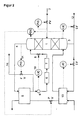
- the process scheme shown in FIG. 2 differs from that in FIG. 1 Scheme shown in that the amount of residual gas discharged to the atmosphere not as a function of a flow regulator 15, but via a pressure regulator 11 is set by the pressure at the top of the pure argon column 1. Through this pressure control instabilities of the rectification process in the pure argon column 1 are additional decreased.
Abstract
Description
Die Erfindung betrifft ein Verfahren zur Zerlegung eines Gasgemisches durch Tieftemperaturrektifkation, bei dem am Kopf einer Destillationskolonne eine leichterflüchtige Kopffraktion gewonnen wird, zumindest ein Teil der Kopffraktion zu einem Wärmetauscher geleitet wird, in dem Wärmetauscher in indirektem Wärmeaustausch mit einem Kühlmedium zumindest teilweise verflüssigt wird und das dabei entstehende Kondensat über eine Rückleitung zur Destillationskolonne geleitet wird. Ferner bezieht sich die Erfindung auf eine Vorrichtung zur Zerlegung eines Gasgemisches durch Tieftemperaturrektifikation mit mindestens einer Destillationskolonne und einem Wärmetauscher, wobei der Wärmetauscher über eine Zuleitung für Dampf und eine Rückleitung für Kondensat mit dem oberen Teil der Destillationskolonne verbunden ist.The invention relates to a method for decomposing a gas mixture Low-temperature rectification, in which at the top of a distillation column volatile head fraction is obtained, at least part of the head fraction a heat exchanger is conducted in the heat exchanger in indirect Heat exchange with a cooling medium is at least partially liquefied and that the resulting condensate is fed via a return line to the distillation column becomes. Furthermore, the invention relates to a device for disassembling a Gas mixture by low temperature rectification with at least one Distillation column and a heat exchanger, the heat exchanger via a Inlet for steam and a return line for condensate with the upper part of the Distillation column is connected.
In Tieftemperaturrektifikationsanlagen mit Argongewinnung wird in der Regel die Einsatzluft zunächst in einer Doppelsäule zerlegt, wobei sich Argon im mittleren Teil der Niederdruckkolonne anreichert. Aus diesem Bereich wird eine Gasfraktion entnommen, die im wesentlichen aus Sauerstoff und Argon besteht, und zur weiteren Rektifikation einer Rohargonsäule zugeführt. In der Rohargonsäule wird das Rohargon vom Sauerstoff befreit und anschließend zur Stickstoffentfernung in eine Reinargonsäule geleitet.In low-temperature rectification plants with argon extraction, the Feed air is first broken down into a double column, with argon in the middle enriches the low pressure column. This area becomes a gas fraction taken, which consists essentially of oxygen and argon, and for further Rectification fed to a crude argon column. In the crude argon column it will Raw argon freed from oxygen and then in a for nitrogen removal Pure argon column headed.
Um die Rektifikation in der Reinargonsäule zu betreiben, muß dafür gesorgt werden, daß am Kopf der Säule genügend Rücklauf erzeugt wird. Hierzu wird das am Kopf der Reinargonsäule gewonnene, im wesentlichen aus Stickstoff bestehende Gasgemisch einem Wärmetauscher zugeführt, in diesem in indirektem Wärmeaustausch mit einem Kühlmedium zumindest teilweise verflüssigt und das dabei entstehende Kondensat wieder als Rücklaufflüssigkeit auf die Reinargonsäule aufgegeben. Ein derartiges Verfahren ist beispielsweise aus der EP-A-0 669 509 bekannt.In order to carry out rectification in the pure argon column, care must be taken that enough return is generated at the top of the column. For this, the head of the Pure argon column obtained gas mixture consisting essentially of nitrogen fed to a heat exchanger, in this in indirect heat exchange with a The cooling medium is at least partially liquefied and the condensate formed added back to the pure argon column as reflux liquid. Such a thing The method is known for example from EP-A-0 669 509.
Aus konstruktiven und mechanischen Gründen ist es oft sinnvoll, den Wärmetauscher, der als Kondensator für die Reinargonsäule dient, nicht direkt an den Kopf der Reinargonsäule zu setzen, sondern von der Reinargonsäule beabstandet vorzusehen. In diesem Fall wird die gasförmige Kopffraktion der Reinargonsäule über eine Zuleitung in den Warmetauscher geleitet und das Kondensat über eine Rückleitung wieder zur Reinargonsäule zurückgeführt.For design and mechanical reasons, it is often advisable to use the Heat exchanger, which serves as a condenser for the pure argon column, not directly to the Head of the pure argon column, but spaced from the pure argon column to provide. In this case the gaseous top fraction of the pure argon column is over a supply line into the heat exchanger and the condensate via a The return line is returned to the pure argon column.
Es hat sich allerdings gezeigt, daß bei beabstandeten Wärmetauschern schon geringe Mengenänderungen der gasförmigen Kopffraktion zu einem instabilen Verhalten der Reinargonsäule führen können. Die gleichen Probleme können bei allen Kolonnen, nicht nur Reinargonsäulen, auftreten, bei denen das im Wärmetauscher erzeugte Kondensat über eine Rückleitung zur Kolonne zurückgeführt wird.However, it has been shown that with spaced-apart heat exchangers small changes in the amount of the gaseous top fraction to an unstable Behavior of the pure argon column. The same problems can arise with all columns, not just pure argon columns, occur in which the Heat exchanger generated condensate via a return line to the column is returned.
Aufgabe vorliegender Erfindung ist es daher, ein Verfahren und eine Vorrichtung der eingangs genannten Art dahingehend zu verbessern, daß der Rektifikationsprozeß in der Destillationskolonne auch bei Mengenänderungen der dem Wärmetauscher zugeführten Gasmenge im wesentlichen stabil verläuft.The object of the present invention is therefore to provide a method and an apparatus for to improve the kind mentioned in the introduction so that the rectification process in the distillation column even with changes in the quantity of the heat exchanger amount of gas supplied is essentially stable.
Diese Aufgabe wird dadurch gelöst, daß zumindest ein Teil des Kondensats in der Rückleitung aufgestaut wird.This object is achieved in that at least part of the condensate in the Return line is dammed.
Die Erfindung beruht auf der Erkenntnis, daß aufgrund der Strömungswiderstände und der Speicherfähigkeit für Flüssigkeiten in den Leitungen zu und vom Wärmetauscher auch geringfügige Änderungen der dem Wärmetauscher zugeleiteten Gasmenge, wie sie beispielsweise aufgrund von Zulauf- oder Druckschwankungen entstehen können, totzeitbehaftet auf die Menge an Rücklaufflüssigkeit übertragen werden. Die dabei entstehenden Totzeiten sind besonders groß, wenn die Strömungsgeschwindigkeit klein und / oder die Leitungslänge groß ist. Diese Totzeiten führen dazu, daß in der Destillationskolonne das Rücklaufverhältnis, d.h das Verhältnis von Rücklaufmenge zu Gasmenge schwankt, so daß Abweichungen von den optimalen Betriebsbedingungen der Destillationskolonne auftreten.The invention is based on the knowledge that due to the flow resistance and the storage capacity for liquids in the lines to and from Heat exchanger also minor changes in the supplied to the heat exchanger Amount of gas, such as that due to fluctuations in supply or pressure transferred to the amount of reflux liquid become. The resulting dead times are particularly long if the Flow speed is small and / or the line length is long. This Dead times mean that the reflux ratio, i.e. the The ratio of the return flow to the gas flow fluctuates, so that deviations from the optimal operating conditions of the distillation column.
Durch das erfindungsgemäße Aufstauen von Kondensat in der Rückleitung wird eine Änderung der dem Wärmetauscher zugeführten Gasmenge, die aufgrund der hohen Strömungsgeschwindigkeit des Gases sehr schnell zu entsprechenden Mengenänderungen am Wärmetauschereingang führt, schneller als bisher auf die Rücklaufmenge in die Destillationskolonne übertragen. Durch den Teil der Rückleitung, in dem Kondensat aufgestaut ist, werden Mengenänderungen ohne merkliche Strömungstotzeiten übertragen. Bisher pflanzte sich dagegen eine derartige Änderung nur mit der Fließ- oder Tropfgeschwindigkeit des Kondensats durch die Rückleitung fort. Das Rücklaufverhältnis in der Destillationskolonne wird so erfindungsgemäß stets auf dem optimalen Wert gehalten.Due to the accumulation of condensate in the return line according to the invention Change in the amount of gas supplied to the heat exchanger due to the high Flow rate of the gas very quickly to corresponding Changes in quantity at the heat exchanger inlet leads to the faster than before Transfer the reflux quantity into the distillation column. Through the part of the Return line, in which condensate is accumulated, changes in quantity without noticeable current dead times transmitted. So far, however, has been planted Change only with the flow or drip rate of the condensate through the Return continues. The reflux ratio in the distillation column is like this according to the invention always kept at the optimal value.
Das erfindungsgemäße Aufstauen von Kondensat erfolgt nicht in einem eigens hierfür vorgesehenen Speicherbehälter, sondern in der ohnehin vorhandenen Rückleitung. Unter dem Begriff Rückleitung wird eine Leitung verstanden, die bei dem eingangs beschriebenen Verfahren zwingend erforderlich ist, deren Größe und Durchmesser in der Regel an den Umsatz des Wärmetauschers angepaßt sind und deren Länge meist sehr viel größer ist als deren Durchmesser.The accumulation of condensate according to the invention does not take place in a specially for this provided storage container, but in the already existing return line. The term return line is understood to mean a line which at the beginning described method is mandatory, the size and diameter in are usually adapted to the turnover of the heat exchanger and their length is usually much larger than their diameter.
Von Vorteil wird in mehr als 50 %, bevorzugt mehr als 75 %, besonders bevorzugt mehr als 90 %, des Volumens der Rückleitung Kondensat aufgestaut. Je mehr Volumen der Rückleitung mit Kondensat gefüllt ist, eine desto kürzere Strömungstotzeit in der Rücklaufmenge in die Destillationskolonne stellt sich ein.Advantage is particularly preferred in more than 50%, preferably more than 75% more than 90% of the volume of the return condensate pent up. The more Volume of the return line is filled with condensate, the shorter Flow dead time in the return flow into the distillation column arises.
Vorzugsweise wird die Menge des aus der Rückleitung in die Destillationskolonne geleiteten Kondensats in Abhängigkeit von der Menge des in der Rücklaufleitung aufgestauten Kondensats geregelt. Hierzu kann beispielsweise am Ausgang der Rückleitung, d.h. unmittelbar vor der Destillationskolonne, ein Ventil angeordnet sein. Dieses erhält sein Stellsignal beispielsweise von einem Füllstandsregler, welcher mit einem Sensor verbunden ist, der den Füllstand in der Rückleitung bestimmt.Preferably, the amount of from the return line to the distillation column conducted condensate depending on the amount of in the return line dammed condensate regulated. For this purpose, the Return, i.e. a valve may be arranged immediately upstream of the distillation column. This receives its control signal, for example, from a fill level controller, which also is connected to a sensor that determines the level in the return line.
Bei Störungen des Betriebs der Destillationskolonne, die zu einer Erhöhung der am Kopf der Destillationskolonne entstehenden Gasmenge führen, tritt aus dem Wärmetauscher eine größere Menge an Kondensat aus, wodurch auch die in der Rückleitung aufgestaute Kondensatmenge ansteigt. Der Anstieg der in der Rückleitung aufgestauten Kondensatmenge wird erfaßt und bewirkt, z.B. durch stärkere Öffnung eines in der Rückleitung angebrachten Ventils, eine Erhöhung der aus der Rückleitung in die Destillationskolonne fließenden Kondensatmenge. Bei einer Verringerung der am Kopf der Destillationskolonne austretenden Gasmenge wird in analoger Weise verfahren. Das Rücklaufverhältnis in der Destillationskolonne bleibt so auch bei Betriebsstörungen, wie z.B. Druck- oder Zulaufschwankungen, konstant.In the event of malfunctions in the operation of the distillation column, which leads to an increase in the Lead head of the distillation column resulting amount of gas emerges from the Exchanger a larger amount of condensate, which also causes the in the Return line accumulated amount of condensate increases. The rise in the Return line of accumulated condensate is detected and caused, e.g. by greater opening of a valve installed in the return line, an increase in the amount of condensate flowing from the return line into the distillation column. At a reduction in the amount of gas leaving the top of the distillation column is operated in an analogous manner. The reflux ratio in the distillation column remains so even in the event of malfunctions, e.g. Pressure or inlet fluctuations, constant.
Vorzugsweise wird die Kopffraktion in dem Wärmetauscher in indirektem Wärmeaustausch mit einer sauerstoffhaltigen Fraktion verflüssigt.Preferably, the top fraction in the heat exchanger is indirect Liquefied heat exchange with an oxygen-containing fraction.
Von Vorteil wird neben der Kopffraktion eine weitere Fraktion in indirektem Wärmeaustausch mit dem Kühlmedium abgekühlt oder zumindest teilweise verflüssigt. Besonders vorteilhaft ist es, wenn die weitere Fraktion in dem Wärmetauscher in indirektem Wärmeaustausch mit dem Kühlmedium abgekühlt oder zumindest teilweise verflüssigt wird. Durch die Erfindung werden die eingangs beschriebenen Nachteile hinsichtlich Totzeiten und Zeitverzögerungen, die bisher bei Wärmetauschern bzw. Kondensator-Verdampfern auftraten, die nicht unmittelbar an der Destillationskolonne angeordnet sind, vermieden. Besonders sinnvoll ist es daher, einen gemeinsamen Wärmetauscher für zwei zu kondensierende Fraktionen, beispielsweise die Kopffraktion der Rohargonsäule und die Kopffraktion der Reinargonsäule, vorzusehen. Ein Wärmetauscher mit getrennten Passagen für die beiden zu kondensierenden Fraktionen und das Kühlmedium ist kostengünstiger als zwei separate Wärmetauscher.In addition to the top fraction, another fraction in indirect is advantageous Heat exchange with the cooling medium cooled or at least partially liquefied. It is particularly advantageous if the further fraction in the Cooled heat exchanger in indirect heat exchange with the cooling medium or is at least partially liquefied. By the invention are the beginning Disadvantages described with regard to dead times and time delays, which so far at Heat exchangers or condenser evaporators that did not immediately occur the distillation column are avoided. It is therefore particularly useful a common heat exchanger for two fractions to be condensed, for example the top fraction of the crude argon column and the top fraction of the Pure argon column to be provided. A heat exchanger with separate passages for the both fractions to be condensed and the cooling medium is less expensive than two separate heat exchangers.
Die Erfindung ist insbesondere in den Fällen vorteilhaft, in denen zumindest ein Teil der Kopffraktion gasförmig abgezogen wird. Die abgezogene Gasmenge kann in Abhängigkeit des Drucks oder des Durchflusses eingestellt werden. Vorzugsweise wird zumindest ein Teil der aus dem Wärmetauscher austretenden Kopffraktion gasförmig abgezogen. Besonders vorteilhaft ist es, wenn dieser Teil in Abhängigkeit vom Druck am Kopf der Destillationskolonne abgezogen wird. Bei dieser Verfahrensweise kann über die Regelung des Kopfdrucks der Destillationskolonne die Rektifikation in der Destillationskolonne auch bei Druck- und Mengenschwankungen weiter verbessert werden.The invention is particularly advantageous in cases in which at least a part the top fraction is withdrawn in gaseous form. The amount of gas withdrawn can be in Dependency of the pressure or the flow can be set. Preferably becomes at least a part of the head fraction emerging from the heat exchanger withdrawn in gaseous form. It is particularly advantageous if this part is dependent is subtracted from the pressure at the top of the distillation column. At this The procedure can be controlled by controlling the top pressure of the distillation column Rectification in the distillation column even with pressure and volume fluctuations be further improved.
Die Erfindung eignet sich insbesondere bei Verfahren, bei denen ein mit Argon angereichertes Gasgemisch in einer Reinargonsäule zerlegt und am Kopf der Reinargonsäule eine im wesentlichen Stickstoff enthaltende Kopffraktion gewonnen wird, zumindest ein Teil der Kopffraktion zu einem Wärmetauscher geleitet, in dem Wärmetauscher in indirektem Wärmeaustausch mit einem Kühlmedium zumindest teilweise verflüssigt wird und das dabei entstehende Kondensat über eine Rückleitung zur Reinargonsäule geleitet wird, wobei zumindest ein Teil des Kondensats in der Rückleitung aufgestaut wird.The invention is particularly suitable in processes in which an argon Enriched gas mixture disassembled in a pure argon column and at the top of the Pure argon column obtained a head fraction containing essentially nitrogen , at least part of the top fraction is passed to a heat exchanger in which Heat exchanger in indirect heat exchange with a cooling medium at least is partially liquefied and the resulting condensate via a return line is passed to the pure argon column, with at least part of the condensate in the Return line is dammed.
Bei Verfahren zur Gewinnung von Reinargon, bei denen zunächst eine argonhaltige Fraktion in eine Rohargonsäule eingeleitet und an deren Kopf sauerstoffarmes Argon gewonnen wird und zumindest ein Teil des sauerstoffarmen Argons in indirektem Wärmeaustausch verflüssigt wird, ist es vorteilhaft, das sauerstoffarme Argon mit demselben Kühlmedium zumindest teilweise zu verflüssigen, mit dem die am Kopf der Reinargonsäule gewonnene Kopffraktion zumindest teilweise verflüssigt wird. Besonders günstig ist der Einsatz von Sauerstoff, bevorzugt von Sumpfflüssigkeit aus der Druckstufe einer Doppelsäule, als Kühlmedium.In processes for the production of pure argon, which initially involve an argon Fraction introduced into a crude argon column and at the top low-oxygen argon is obtained and at least part of the oxygen-poor argon in indirect Heat exchange is liquefied, it is advantageous to use the low-oxygen argon to at least partially liquefy the same cooling medium with which at the head of the Reinargonsäule obtained head fraction is at least partially liquefied. The use of oxygen, preferably from the bottom liquid, is particularly favorable the pressure level of a double column as a cooling medium.
Aus Kostengründen ist es besonders sinnvoll, die aus der Rohargonsäule und die aus der Reinargonsäule gewonnenen Kopffraktionen in demselben Wärmetauscher zumindest teilweise zu verflüssigen.For cost reasons, it is particularly useful to use the raw argon column and the head fractions obtained from the pure argon column in the same heat exchanger at least partially liquefy.
Neben dem Verfahren bezieht sich die Erfindung auch auf eine Vorrichtung zur Zerlegung eines Gasgemisches durch Tieftemperaturrektifikation mit mindestens einer Destillationskolonne und einem Wärmetauscher, wobei der Wärmetauscher über eine Zuleitung für Dampf und eine Rückleitung für Kondensat mit dem oberen Teil der Destillationskolonne verbunden ist.In addition to the method, the invention also relates to a device for Decomposition of a gas mixture by low temperature rectification with at least one Distillation column and a heat exchanger, the heat exchanger via a Inlet for steam and a return line for condensate with the upper part of the Distillation column is connected.
Erfindungsgemäß befindet sich in dem mit der Destillationskolonne verbundenen Endbereich der Rückleitung ein Ventil, welches ein Stellsignal von einem Füllstandsregler erhält, der mit einer die in der Rückleitung gespeicherte Flüssigkeitsmenge messenden Meßvorrichtung verbunden ist.According to the invention is in the connected to the distillation column End area of the return line a valve, which is an actuating signal from a Level controller receives the one stored in the return line Liquid quantity measuring device is connected.
Der Füllstandsregler ist mit einer die in der Rückleitung gespeicherte Flüssigkeitsmenge messenden Meßvorrichtung verbunden, die sich vorzugsweise in den ersten 50 %, besonders bevorzugt in den ersten 25 %, ganz besonders bevorzugt in den ersten 10 %, der Rückleitung, ausgehend vom Wärmetauscher, befindet. The level controller is one that is stored in the return line Liquid quantity measuring device connected, which is preferably in the first 50%, particularly preferably in the first 25%, very particularly preferably in the first 10%, the return line, starting from the heat exchanger, located.
Die Erfindung sowie weitere Einzelheiten der Erfindung werden im folgenden anhand von in den schematischen Zeichnungen dargestellten Ausführungsbeispielen näher erläutert. Hierbei zeigen
Figur 1- einen Ausschnitt aus einem Verfahrensschema einer Luftzerlegungsanlage zur Gewinnung von Reinargon und
Figur 2- eine Variante des in
Figur 1 dargestellten Verfahrens.
- Figure 1
- a section of a process diagram of an air separation plant for the production of pure argon and
- Figure 2
- a variant of the method shown in Figure 1.
Gemäß Figur 1 wird über Leitung 2 einer Reinargonsäule 1 ein im wesentlichen Argon
und Stickstoff enthaltendes Gasgemisch zugeführt. In der Reinargonsäule 1 wird
dieses Gemisch in Reinargon, welches am Sumpf 3 der Säule 1 abgezogen wird, und
eine im wesentlichen aus Stickstoff bestehende Kopffraktion zerlegt. Die
Sumpffraktion wird zum Teil über die Leitung 12 als Reinargonprodukt entnommen,
zum Teil im Verdampfer 13 gegen flüssigen Rohsauerstoff aus dem Sumpf der nicht
dargestellten Drucksäule verdampft und in das untere Drittel der Reinargonsäule 1
eingeleitet. Die in der Säule 1 entstehende Kopffraktion wird über Leitung 4 einem als
Verdampfer-Kondensator arbeitenden Wärmetauscher 5 zugeleitet. In diesem
Wärmetauscher 5 wird die Kopffraktion gegen den aus dem Wärmetauscher 13
austretenden, flüssigen Rohsauerstoff zumindest teilweise kondensiert.According to FIG. 1, essentially argon is introduced via
Aus dem Wärmetauscher 5 tritt ein im wesentlichen aus Stickstoffkondensat und
Restgas bestehendes Zwei-Phasen-Gemisch aus. Das Restgas wird über Leitung 14
in die Atmosphäre abgeführt, wobei die Regelung der abgegebenen Restgasmenge
über einen Mengenregler 15 erfolgt. Das Kondensat wird über die Rückleitung,
welche aus einem ersten Abschnitt 6 und einem zweiten Abschnitt 7 besteht, zurück
zur Reinargonsäule 1 geleitet und im oberen Drittel dieser Säule 1 als
Rücklaufflüssigkeit wieder aufgegeben. Der zweite Abschnitt 7 ist als U-Rohr
ausgebildet, so daß sich im unteren Bogen des U-Rohres 7 das Kondensat sammelt
und so den Austritt von Gas aus der Rückleitung 7 in die Reinargonsäule 1 verhindert.From the
Der in der Reinargonsäule 1 erlaubte Druck ist nach oben durch den in der
Rohargonsäule herrschenden Druck von etwa 1,2 bis 1,5 bar beschränkt, da
ansonsten die Zufuhr von Rohargon in die Reinargonsäule 1 ohne Hilfsmittel nicht
möglich wäre. Zum anderen muß der Druck in der Reinargonsäule 1 zumindest so
groß wie der Atmosphärendruck sein, um beispielsweise Restgas über Leitung 14 an
die Umgebung abgeben zu können, ohne dabei Falschluft einzuziehen. Aufgrund
dieses engen erlaubten Druckbereichs ist es besonders wichtig, daß das
Rücklaufverhältnis in der Reinargonsäule 1 immer am Optimum liegt. Dies gilt
allgemein für alle Kolonnen, die in einem engen Druckbereich betrieben werden.The pressure allowed in the
Am Ende des Abschnitts 7 befindet sich ein Ventil 8, welches sein Stellsignal von
einem Füllstandsregler 10 erhält. Dieser steht mit einer unmittelbar nach dem
Wärmetauscher 5 angeordneten Meßstelle 9 in Verbindung. Mit der Meßvorrichtung 9
wird der Flüssigkeitsstand in der Rückleitung 6, 7 gemessen. Nahezu in der gesamten
Rückleitung 6, 7 wird Kondensat aufgestaut.At the end of
Fällt in der Reinargonsäule 1 eine erhöhte Gasmenge am Kopf der Säule 1 an, so
entsteht als Reaktion darauf am Ausgang des Wärmetauschers 5 eine erhöhte Menge
Kondensat. Dadurch steigt der Flüssigkeitsstand in der Leitung 6, 7 an. Dies wird
durch die Meßvorrichtung 9 registriert und ein entsprechendes Signal an den
Füllstandsregler 10 abgegeben. Aufgrund eines Regelalgorithmus wird das Ventil 8
daraufhin weiter geöffnet, so daß sich die aus der Rückleitung 7 austretende
Kondensatmenge und damit der Rücklauf in der Säule 1 erhöht. Das
Rücklaufverhältnis in der Säule 1 bleibt dadurch konstant. Entsprechendes gilt auch
für eine reduzierte Gasmenge am Kopf der Säule 1.If there is an increased amount of gas at the top of
Das in Figur 2 gezeigte Verfahrensschema unterscheidet sich von dem in Figur 1
dargestellten Schema darin, daß die an die Atmosphäre abgeführte Restgasmenge
nicht über einen Mengenregler 15, sondern über einen Druckregler 11 in Abhängigkeit
vom Druck am Kopf der Reinargonsäule 1 eingestellt wird. Durch diese Druckregelung
werden Instabilitäten des Rektifikationsprozesses in der Reinargonsäule 1 zusätzlich
verringert.The process scheme shown in FIG. 2 differs from that in FIG. 1
Scheme shown in that the amount of residual gas discharged to the atmosphere
not as a function of a
Claims (14)
Applications Claiming Priority (2)
| Application Number | Priority Date | Filing Date | Title |
|---|---|---|---|
| DE19810535 | 1998-03-11 | ||
| DE19810535 | 1998-03-11 |
Publications (1)
| Publication Number | Publication Date |
|---|---|
| EP0942246A2 true EP0942246A2 (en) | 1999-09-15 |
Family
ID=7860513
Family Applications (1)
| Application Number | Title | Priority Date | Filing Date |
|---|---|---|---|
| EP19980113198 Withdrawn EP0942246A2 (en) | 1998-03-11 | 1998-07-15 | Process and device for air separation |
Country Status (2)
| Country | Link |
|---|---|
| EP (1) | EP0942246A2 (en) |
| DE (1) | DE19831830A1 (en) |
Cited By (6)
| Publication number | Priority date | Publication date | Assignee | Title |
|---|---|---|---|---|
| DE102007035619A1 (en) | 2007-07-30 | 2009-02-05 | Linde Ag | Process and apparatus for recovering argon by cryogenic separation of air |
| EP2026024A1 (en) | 2007-07-30 | 2009-02-18 | Linde Aktiengesellschaft | Process and device for producing argon by cryogenic separation of air |
| DE102009016043A1 (en) | 2009-04-02 | 2010-10-07 | Linde Ag | Method for operating a pure argon column, comprises initiating a nitrogen-containing argon stream into an upper- or middle area of the pure argon column from which lower area of the argon column is drawn-off to a pure argon product |
| WO2014135271A2 (en) | 2013-03-06 | 2014-09-12 | Linde Aktiengesellschaft | Air separation plant, method for obtaining a product containing argon, and method for creating an air separation plant |
| DE102013018664A1 (en) | 2013-10-25 | 2015-04-30 | Linde Aktiengesellschaft | Process for the cryogenic separation of air and cryogenic air separation plant |
| EP3040665A1 (en) | 2014-12-30 | 2016-07-06 | Linde Aktiengesellschaft | Distillation system and plant for the production of oxygen by crygenic separation of air |
-
1998
- 1998-07-15 EP EP19980113198 patent/EP0942246A2/en not_active Withdrawn
- 1998-07-15 DE DE19831830A patent/DE19831830A1/en not_active Withdrawn
Cited By (6)
| Publication number | Priority date | Publication date | Assignee | Title |
|---|---|---|---|---|
| DE102007035619A1 (en) | 2007-07-30 | 2009-02-05 | Linde Ag | Process and apparatus for recovering argon by cryogenic separation of air |
| EP2026024A1 (en) | 2007-07-30 | 2009-02-18 | Linde Aktiengesellschaft | Process and device for producing argon by cryogenic separation of air |
| DE102009016043A1 (en) | 2009-04-02 | 2010-10-07 | Linde Ag | Method for operating a pure argon column, comprises initiating a nitrogen-containing argon stream into an upper- or middle area of the pure argon column from which lower area of the argon column is drawn-off to a pure argon product |
| WO2014135271A2 (en) | 2013-03-06 | 2014-09-12 | Linde Aktiengesellschaft | Air separation plant, method for obtaining a product containing argon, and method for creating an air separation plant |
| DE102013018664A1 (en) | 2013-10-25 | 2015-04-30 | Linde Aktiengesellschaft | Process for the cryogenic separation of air and cryogenic air separation plant |
| EP3040665A1 (en) | 2014-12-30 | 2016-07-06 | Linde Aktiengesellschaft | Distillation system and plant for the production of oxygen by crygenic separation of air |
Also Published As
| Publication number | Publication date |
|---|---|
| DE19831830A1 (en) | 1999-09-16 |
Similar Documents
| Publication | Publication Date | Title |
|---|---|---|
| EP0399197B1 (en) | Process and apparatus for the low temperature separation of air | |
| EP0895045B1 (en) | Air separation process | |
| EP1845324A1 (en) | Process and device for producing a high pressure product by cryogenic air separation | |
| DE102005029274A1 (en) | Obtaining gaseous pressure product, by cryogenic separation of air implementing normal operation, emergency operation, and bypass operation | |
| EP0669509A1 (en) | Process and apparatus for obtaining pure argon | |
| EP0538857B1 (en) | Installation for the low temperature separation | |
| DE19507981A1 (en) | Air distillation argon column base linked by pipe and valve to main assembly | |
| DE2100397A1 (en) | Automatic regulation process for an air separation plant | |
| EP0942246A2 (en) | Process and device for air separation | |
| DE60004450T2 (en) | Cryogenic rectification system for the production of high-purity oxygen | |
| EP0681153B1 (en) | Process and apparatus for the low temperature separation of air | |
| EP0607887A2 (en) | Apparatus and process for the low temperature air separations and liquid distributor for a mass transfer column | |
| EP3207320B1 (en) | Method and device for variable extraction of argon by cryogenic decomposition of air | |
| DE69908991T2 (en) | Method and device for the low-temperature separation of air | |
| EP1231440A1 (en) | Process and apparatus for air separation by cryogenic distillation | |
| DE10232430A1 (en) | Process for recovering krypton and/or xenon comprises feeding a liquid from the lower region of a krypton-xenon enriching column to a condenser-vaporizer, and contacting an argon-enriched vapor with the liquid from the enriching column | |
| DE10249383A1 (en) | Method and device for the variable generation of oxygen by low-temperature separation of air | |
| DE10332862A1 (en) | Cryogenic assembly to extract krypton and/or xenon gas from air has intermediate pipe on the methane removal column alongside a base panel above the sump | |
| DE69819421T2 (en) | Method and device for producing argon | |
| DE10205096A1 (en) | Process for recovering highly pure oxygen from less pure oxygen in a distillation system comprises feeding the less pure oxygen into high pressure column, feeding fraction into a low pressure column and withdrawing highly pure oxygen | |
| DE10130754A1 (en) | Method and equipment for regulating air-separation plant's capacity incorporate high and low pressure columns, fluid-pipe, regulator, meter and intermediate point | |
| EP0904518B1 (en) | Process for starting an installation for low temperature air separation and installation for low temperature air separation | |
| EP1052465B1 (en) | Process and device for cryogenic air separation | |
| DE958387C (en) | Process for separating air | |
| EP0828122A1 (en) | Process and apparatus for the recovery of argon by low temperature air separation |
Legal Events
| Date | Code | Title | Description |
|---|---|---|---|
| PUAI | Public reference made under article 153(3) epc to a published international application that has entered the european phase |
Free format text: ORIGINAL CODE: 0009012 |
|
| AK | Designated contracting states |
Kind code of ref document: A2 Designated state(s): AT BE CH CY DE DK ES FI FR GB GR IE IT LI LU MC NL PT SE |
|
| AX | Request for extension of the european patent |
Free format text: AL;LT;LV;MK;RO;SI |
|
| STAA | Information on the status of an ep patent application or granted ep patent |
Free format text: STATUS: THE APPLICATION HAS BEEN WITHDRAWN |
|
| 18W | Application withdrawn |
Withdrawal date: 19991208 |