EP0941856B1 - Verfahren und gerät zur bestimmung des tintevolumens in einem tintenbehälter - Google Patents
Verfahren und gerät zur bestimmung des tintevolumens in einem tintenbehälter Download PDFInfo
- Publication number
- EP0941856B1 EP0941856B1 EP99301672A EP99301672A EP0941856B1 EP 0941856 B1 EP0941856 B1 EP 0941856B1 EP 99301672 A EP99301672 A EP 99301672A EP 99301672 A EP99301672 A EP 99301672A EP 0941856 B1 EP0941856 B1 EP 0941856B1
- Authority
- EP
- European Patent Office
- Prior art keywords
- ink
- ink container
- storage device
- volume
- container
- Prior art date
- Legal status (The legal status is an assumption and is not a legal conclusion. Google has not performed a legal analysis and makes no representation as to the accuracy of the status listed.)
- Expired - Lifetime
Links
Images


Classifications
-
- B—PERFORMING OPERATIONS; TRANSPORTING
- B41—PRINTING; LINING MACHINES; TYPEWRITERS; STAMPS
- B41J—TYPEWRITERS; SELECTIVE PRINTING MECHANISMS, i.e. MECHANISMS PRINTING OTHERWISE THAN FROM A FORME; CORRECTION OF TYPOGRAPHICAL ERRORS
- B41J2/00—Typewriters or selective printing mechanisms characterised by the printing or marking process for which they are designed
- B41J2/005—Typewriters or selective printing mechanisms characterised by the printing or marking process for which they are designed characterised by bringing liquid or particles selectively into contact with a printing material
- B41J2/01—Ink jet
- B41J2/17—Ink jet characterised by ink handling
- B41J2/175—Ink supply systems ; Circuit parts therefor
- B41J2/17503—Ink cartridges
- B41J2/17543—Cartridge presence detection or type identification
- B41J2/17546—Cartridge presence detection or type identification electronically
Definitions
- the present invention relates to ink-jet printing systems that make use of a replaceable printing component. More particularly, the present invention relates to replaceable printing components that include an electrical storage device for providing information to the ink-jet printing system.
- Ink-jet printers frequently make use of an ink-jet printhead mounted within a carriage that is moved back and forth across a print media, such as paper.
- a control system activates the printhead to deposit or eject ink droplets onto the print media to form images and text.
- Ink is provided to the printhead by a supply of ink which is either carried by the carriage or mounted to the printing system to not move with the carriage.
- the ink supply can be intermittently or continuously connected to the printhead for replenishing the printhead.
- the replaceable printing components such as the ink container and the printhead, require periodic replacement.
- the ink supply is replaced when exhausted.
- the printhead is replaced at the end of printhead life.
- EP-A-0 789 322 discloses the use of a memory device, which contains parameters relating to the replaceable part. The installation of the replaceable part allows the printer to access the replaceable part parameters to insure high print quality. By incorporating the memory device into the replaceable part and storing replaceable part parameters in the memory device within the replaceable component the printing system can determine these parameters upon installation into the printing system. This automatic updating of printer parameters frees the user from having to update printer parameters each time a replaceable component is newly installed.
- the printing system is capable of accommodating a plurality of different ink container sizes it is important that size information is transferred between the printer and the ink container in a highly reliable and efficient manner. This exchange of information should not require the intervention of the user thereby ensuring greater ease of use and greater reliability. Furthermore, it is important that the integrity of the information be preserved.
- One aspect of the present invention is an ink-jet printing system that includes a printer portion and a replaceable ink container.
- the printer portion is for depositing ink on media in response to control signals.
- the printer portion is configured for receiving a supply of ink.
- the replaceable ink container is for providing a supply of ink to the printer portion.
- the replaceable ink container includes an electrical storage device for providing parameters to the printer portion.
- the electrical storage device includes an ink container scale parameter for selecting an ink container volume range from a plurality of ink container volume ranges. Also included is a fill proportion parameter for specifying a fill proportion for the selected ink volume range.
- the printer portion determines an ink volume associated with the ink container based on the fill proportion parameter and the selected ink volume range.
- Another aspect of the present invention is method for storing ink container parameters in an electrical storage device.
- the electrical storage device is associated with an ink container containing a volume of ink.
- the method includes determining an ink scale parameter associated with an ink volume range for the supply of ink. Also included is determining a fill proportion parameter for the supply of ink. Finally, the method includes storing the ink scale and ink fill parameter in the electrical storage device.
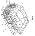
- Fig. 1 is a perspective view of one exemplary embodiment of an ink-jet printing system 10 of the present invention shown with its cover removed.
- the ink-jet printing system 10 includes a printer portion 12 having a plurality of replaceable printing components 14 installed therein.
- the plurality of replaceable printing components 14 include a plurality of printheads for selectively depositing ink in response to control signals and a plurality of ink containers 18 for providing ink to each of the plurality of printheads 16.
- Each of the plurality of printheads 16 is fluidically connected to each of the plurality of ink containers 18 by a plurality of flexible conduits 20.
- Each of the plurality of printheads 16 is mounted in a scanning carriage 22, which is scanned past a print media (not shown) as the print media is stepped through a print zone. As the plurality of printheads are moved relative to the print media, ink is selectively ejected from a plurality of orifices in each of the print plurality of the printheads 16 to form images and text.
- the ink-jet printing system 10 shown in Fig. 1 is configured to receive ink containers 18 having different ink volumes. This is accomplished using several methods, such as, the use of ink containers 18 that are different sizes with each size having a different volume associated therewith. Another technique for providing different ink volumes is to use ink containers 18 of the same size, but vary a volume of ink in each of the ink containers. It is critical that the ink container 18 provides a volume of ink that matches a proper use model for the particular application. Because ink jet inks typically have a limited storage life once inserted into the printer it is important that the ink container be sized sufficiently large to prevent inconveniencing the user with frequent ink container changes and sufficiently small to prevent ink from becoming stale with age. When ink-jet inks have exceeded the storage life and have become stale these inks cannot reliably produce high quality output images.
- One aspect of the present invention is a method and apparatus for storing information on the replaceable printing components 14 for updating operation parameters of the printer portion 12.
- An electrical storage device is associated with each of the replaceable printing components 14.
- the electrical storage device contains information related to the particular replaceable printer component 14.
- Installation of the replaceable printing component 14 into the printer portion 12 allows information to be transferred between the electrical storage device and the printing portion 12 to insure high print quality as well as to prevent the installation of non-compatible replaceable printing components 14.
- the information provided from the replaceable printing component 14 to the printing portion 12 tends to prevent operation of the printing system 10 in a manner which damages the printing system 10 or which reduces the print quality.
- the printing system 10 shown in Fig. 1 makes use of ink containers 18 which are mounted off of the scanning carriage 22, the present invention that it is equally well suited for other types of printing system configurations.
- One such configuration is one where the replaceable ink containers 18 are mounted on the scanning carriage 22.
- the printhead 16 and the ink container 18 may be incorporated into an integrated printing cartridge that is mounted to the scanning carriage 22.
- the printing system 10 may be used in a wide variety of applications such as facsimile machines, postal franking machines and large format type printing systems suitable for use in displays and outdoor signage.
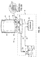
- Figs. 2A and 2B depict a simplified schematic representation of the ink-jet printing system 10 of the present invention shown in Fig. 1.
- Figs. 2A and 2B are simplified to illustrate a single printhead 16 and a single ink container 18 for accomplishing the printing of a single color.
- a plurality of printheads 16 are typically used each having an associated ink container 18 as shown in Fig. 1.
- the ink-jet printing system 10 of the present invention includes a printer portion 12 having replaceable printing components 14.
- the replaceable printing components 14 include a printhead 16 and an ink container 18.
- the printer portion 12 includes an ink container receiving station 24 and a controller 26. With the ink container 18 properly inserted into the ink container receiving station 24, an electrical and a fluidic coupling is established between the ink container 18 and the printer portion 12.
- the fluidic coupling allows ink stored within the ink container 18 to be provided to the printhead 16.
- the electrical coupling allows information to be passed between the ink container 18 and the printer portion 12 to ensure the operation of the printer portion 12 is compatible with the ink contained in the ink container 18 thereby achieving high print quality and reliable operation of the printing system 10.
- the controller 26 controls the transfer of information between the printer portion 12 and the ink container 18. In addition, the controller 26 controls the transfer of information between the printhead 16 and the controller 26. Finally, the controller 26 controls the relative movement of the printhead 16 and the print media as well as selectively activating the printhead to deposit ink on print media.
- the controller 26 is typically implemented with a microprocessor or some form of programmable controller.
- the ink container 18 includes a reservoir 28 for storing ink therein.
- a fluid outlet 30 is provided that it is in fluid communication with the fluid reservoir 28.
- the fluid outlet 30 is configured is for connection to a complimentary fluid inlet 32 associated with the ink container receiving station 24.
- the printhead 16 includes a fluid inlet 34 configured for connection to a complimentary fluid outlet 36 associated with the printing portion 12. With the printhead 16 properly inserted into the scanning carriage 22 (shown in Fig. 1) fluid communication is established between the printhead and the ink container 18 by way of the flexible fluid conduit 20.
- Each of the replaceable printing components 14 such as the printhead 16 and the ink container 18 include an information storage device 38 such as an electrical storage device or memory 38 for storing information related to the respective replaceable printer component 14.
- a plurality of electrical contacts 40 are provided, each of which is electrically connected to the electrical storage device 38. With the ink container 18 properly inserted into the ink container receiving station 24, each of the plurality of electrical contacts 40 engage a corresponding plurality of electrical contacts 42 associated with the ink container receiving station 24. Each of the plurality of electrical contacts 42 associated with the ink container receiving station 24 are electrically connected to the controller 26 by a plurality of electrical conductors 44. With proper insertion of the ink container 18 into the ink container receiving station 24, the memory 38 associated with the ink container 18 is electrically connected to the controller 26 allowing information to be transferred between the ink container 18 and the printer portion 12.
- the printhead 16 includes an information storage device 38 such as an electrical storage device associated therewith.
- a plurality of electrical contacts 40 are electrically connected to the electrical storage 38 in a manner similar to the electrical storage device 38 associated with the ink container 18. With the printhead 16 properly inserted into the scanning carriage 22 the plurality of electrically contacts 40 engage a corresponding plurality of electrical contacts 42 associated with the printing device 12.
- the electrical storage device 38 associated with the printhead 16 is electrically connected to the controller 26 by way of a plurality of electrical conductors 46.
- electrical storage devices 38 associated with each of the ink container 18 and the printhead 16 are given the same element number to indicate these devices are similar, the information stored in the electrical storage device 38 associated with the ink container 18 will, in general, be different from the information stored in the electrical storage device 38 associated with the printhead 16. Similarly, the information stored in electrical storage device 38 associated with each ink container of the plurality of ink container 18 will in general be different and unique to be particular ink container of the plurality of ink containers 18. The particular information stored on each electrical storage device 38 will be discussed in more detail later.
- Fig. 3 represents a block diagram of the printing system 10 of the present invention shown connected to an information source or host computer 48.
- the host computer 48 is shown connected to a display device 50.
- the host 48 can be a variety of information sources such as a personal computer, work station, or server to name a few, that provides image information to the controller 26 by way of a data link 52.
- the data link 52 may be any one of a variety of conventional data links such as an electrical link or an infrared link for transferring information between the host 48 and the printing system 10.
- the controller 26 is electrically connected to the electrical storage devices 38 associated with each of the printhead 16 and the ink container 18. In addition, the controller 26 is electrically connected to a printer mechanism 54 for controlling media transport and movement of the carriage 22. The controller 26 makes use of parameters and information provided by the host 48, the memory 38 associated with the ink container 18 and memory 38 associated with the printhead 16 to accomplish printing.
- the host computer 48 provides image description information or image data to the printing system 10 for forming images on print media.
- the host computer 48 provides various parameters for controlling operation of the printing system 10, which is typically resident in printer control software typically referred to as the "print driver".
- printer control software typically referred to as the "print driver”.
- the operation of the controller 26 compensate for the particular replaceable printer component 14 installed within the printing system 10. It is the electric storage device 38 that is associated with each replaceable printer component 14 that provides parameters particular to the replaceable printer component 14 that allows the controller 26 to utilize these parameters to ensure the reliable operation of the printing system 10 and insure high quality print images.
- parameters for example which can be stored in electrical storage device 38 associated with the replaceable printing component 14 are the following: actual count of ink drops emitted from the printhead 16; a date code associated with the ink container 18; date code of initial insertion of the ink container 18; system coefficients; ink type/color: ink container size; age of the ink; printer model number or identification number; cartridge usage information; just to name a few.
- the electrical storage device 38 shown in Fig. 2A and 2B is a four terminal device.
- the electrical storage device 38 can be a two terminal device.
- One such two terminal device includes a power and ground terminals. Clock signals and data signals are provided on the power terminal.
- An example of such a two terminal memory device is a 1K Bit read/write Electrically Programmable Read Only Memory (EPROM) such as the Dallas Semiconductor part number DS 1982, manufactured by the Dallas Semiconductor Corporation.
- EPROM Electrically Programmable Read Only Memory
- the technique of the present invention allows ink volume information to be passed between the replaceable consumable 14 and the controller 26 in an efficient and reliable manner. It is frequently desirable to pass very accurate ink volume information between the replaceable consumable 14 and the controller 26.
- the replaceable consumable 14 is the ink container 18 it is necessary to have accurate ink volume information associated with the ink supply 28 passed to the controller 26 when the ink container 18 is initially inserted into the printing system 10. This information is used by the printing system 10 to compute remaining ink in the ink supply 28 based on ink usage. Therefore, it is critical that very accurate ink volume information be associated with the ink supply 28 and that this information is accurately provided to the controller 26.
- the controller 26 uses this ink volume information as a basis for determining an out-of-ink condition. It is important that this out-of-ink condition be determined accurately such that the printer is not operated without ink. Operation of the printer without ink can cause reliability problems or, if long enough, produce catastrophic failure.
- the technique of the present invention must not only be capable of providing accurate ink volume information but also capable of providing accurate ink volume information over a large ink volume range.
- the ink volume range varies with the particular printing application. For example, large format printing requires ink containers that are typically several liters in size as a convenience to the user. Significantly smaller ink containers would require greater frequency of ink container replacement which if frequent enough can be an inconvenience to the user.
- the ink container 18 may contain a significantly lower volume of ink in the order of 100 cubic centimeters (cc's) or less. Ink containers of larger volume for this application would likely result exceeding its shelf life or storage period thereby resulting in reduced print quality. In addition, ink use rate for a given application depends on the particular usage for the individual user.
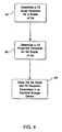
- Fig. 4 depicts the technique of the present invention for storing ink volume information in the electrical storage device 38.
- An ink scale parameter is first determined for the ink volume associated with the ink container 18 as represented by step 56.
- the ink scale parameter identifies an ink container volume range from a plurality of ink container volume ranges. For example, in the preferred embodiment for ink container volume ranges are used as shown in Table 1.
- the ink container scale parameter is a two-bit binary value that is used to uniquely identify each of the four ink container volume ranges. For example, the two-bit binary value of 00 represents an ink container volume range from 0 - 255.75 cubic centimeters (cc's).
- an ink container scale parameter value equal to 11, binary, represents an ink container volume range from 0 - 2,046 cubic centimeters.
- Ink Container Scale Parameter Ink Container Volume Ranges In cc's Resolution For 10 Bit Fill Proportion Parameter In cc's 00 0.00 to 255.75 0.25 01 0.00 to 511.50 0.50 10 0.00 to 1023 1.0 11 0.00 to 2046 2.0
- a fill proportion parameter is then determined for the supply of ink for the ink container 18 as represented by step 58.
- the fill proportion parameter identifies the proportion of the selected ink container volume range that represents the ink volume associated with the ink container 18.
- the fill proportion parameter is a 10-bit binary value. This 10-bit binary value can uniquely identify up to 2 10 or 1,024 unique values.
- An ink volume resolution associated with the ink container 18 then varies with the ink container volume range. For example, the resolution is represented by a maximum ink container volume in the ink container range divided by the number of the unique fill proportion parameter values.
- the ink volume resolution is equal to 255.75 divided by 1, 024 or approximately 0.25 cubic centimeters as shown in Table 1. Therefore, the accuracy in which the fill proportion parameter can specify the ink container volume when the ink scale parameter value selected is equal to 00 selected is .25 cubic centimeters. In the case where the ink container scale parameter value is 11 binary representing a much larger ink container volume range (0 - 2,046) then the resolution of the fill proportion parameter is 2.0 cubic centimeters.
- the ink scale and the fill proportion parameters are then stored in the electrical storage device 38 associated with the ink container 18 as represented by step 60.
- Fig. 6 depicts a method for reading the contents of the electrical storage device 38 that has an indeterminate size prior to insertion into the printing system 10.
- the printing system 10 is capable of accepting ink containers 18 that have varying ink container volumes.
- the technique of the present invention allows the particular ink volume associated with the ink container 18 to be accurately specified using minimal resources in the electrical storage device 38.
- the printing system when powered up represented by step 62 or when the ink container 18 is newly installed represented by step 64 a memory read request represented by steps 66 and 68 is initiated by the controller 26.
- This read request directs the electrical storage device 38 to provide the ink container scale parameter and the fill proportion parameter to the controller 26.
- the controller 26 interprets this information to determine the volume of ink associated with the ink container 18 as represented by step 70.
- the printing system 10 is then ready for accepting a print command from the host as represented by step 72.
- the technique of the present invention allows large ink volumes to be accommodated while providing improved resolution when low ink volume ranges are used. For example, for the case where the ink container scale parameter and the fill proportion parameter are combined into a single twelve bit binary value representing ink volume associated with the ink container 18 then there are 2 12 unique values or 4,096 unique values to specify ink volume. Dividing the maximum ink volume the system must accommodate or 2,046 cc's by the number of unique values or 4,096 yields the ink volume resolution that is approximately .5 cubic centimeters. In contrast, the technique of the present invention allows a resolution of .25 for low ink container volume ranges thereby providing improved resolution by a factor of 2 for the low ink container volume range.
- This improvement in resolution at the low volume range is accomplished without requiring additional information i.e. 12 total bits of information.
- the improvement in resolution is greatest for the low ink container volume ranges.
- the resolution where resolution is most important is actually decreased slightly for the high ink container volume range. This improvement in the low ink container volume range becomes more dramatic the greater the difference in ink container volume range between the highest range and the lowest range.
- the present invention has been described with respect to the preferred embodiment where the replaceable printing components are the printhead portion 16 mounted on the print carriage 22 and the ink container 18 mounted off of the print carriage 22 the present invention is suited for other printer configurations as well.
- the printhead portion and the ink container portion may each be mounted on the printing carriage 22.
- each of the printhead portion and the ink container portion are separately replaceable.
- Each of the printhead portion and the ink container includes an electrical storage portion 38 for providing information to the printing portion 12.
- Each ink container of a plurality of ink containers may be separately replaceable or replaceable as an integrated unit. For the case where the plurality of ink containers is integrated into a single replaceable printing component then only a single electrical storage portion 38 is required for this single replaceable printing component.
Landscapes
- Ink Jet (AREA)
Claims (13)
- Ein Tintenstrahldrucksystem (10) mit folgenden Merkmalen:wobei der Druckerabschnitt (12) ein Tintenvolumen, das dem Tintenbehälter (18) zugeordnet ist, basierend auf dem Füllanteil-Parameter und dem ausgewählten Tintenvolumenbereich bestimmt.einem Druckerabschnitt (12) zum Aufbringen von Tinte auf Medien ansprechend auf Steuerungssignale, wobei der Druckerabschnitt (12) zum Aufnehmen eines Tintenvorrats konfiguriert ist;einem austauschbaren Tintenbehälter (18) zum Bereitstellen eines Tintenvorrats an den Druckerabschnitt, wobei der austauschbare Tintenbehälter (18) eine elektrische Speichervorrichtung (38) zum Bereitstellen von Parametern an den Druckerabschnitt umfaßt, wobei die elektrische Speichervorrichtung (38) folgende Merkmale aufweist:einen Tintenbehälterskala-Parameter zum Auswählen eines Tintenbehältervolumenbereichs aus einer Mehrzahl von Tintenbehältervolumenbereichen,einen Füllanteil-Parameter zum Spezifizieren eines Füllanteils für den ausgewählten Tintenvolumenbereich,
- Das Tintenstrahldrucksystem (10) gemäß Anspruch 1, bei dem der Tintenbehälterskala-Parameter ein 2-Bit-Binärwert ist.
- Das Tintenstrahldrucksystem (10) gemäß Anspruch 1, bei dem der Füllanteil ein 10-Bit-Binärwert ist, der einen Anteil des ausgewählten Tintenvolumenbereichs spezifiziert.
- Das Tintenstrahldrucksystem (10) gemäß Anspruch 1, bei dem der Druckerabschnitt (12) eine Mehrzahl von Tintenvolumenbereichen enthält, wobei jeder der Mehrzahl von Tintenvolumenbereichen eine Mehrzahl entsprechender Tintenbehältervolumenskala-Parameter aufweist, die denselben zugeordnet sind.
- Das Tintenstrahldrucksystem (10) gemäß Anspruch 1, bei dem der austauschbare Tintenbehälter (18) eine elektrische Speichervorrichtung (38) umfaßt, wobei die elektrische Speichervorrichtung (38) den Tintenfüll-Parameter und den Tintenskala-Parameter enthält.
- Ein Tintenbehälter (18) zum Bereitstellen von Tinte an einen Tintenstrahldrucker (12), wobei der Tintenbehälter (18) folgende Merkmale aufweist:ein Reservoir (28), das einen Tintenvorrat enthält; undeine elektrische Speichervorrichtung (38) zum Bereitstellen von Tintenbehälter-Parametern an den Tintenstrahldrucker (12), wobei die elektrische Speichervorrichtung (38) folgende Merkmale enthält:einen Tintenskala-Parameter zum Auswählen eines Tintenvolumenbereichs aus einer Mehrzahl von Tintenvolumenbereichen; undeinen Füllanteil-Parameter zum Spezifizieren eines Füllanteils für den ausgewählten Tintenvolumenbereich, der dem Tintenvorrat in dem Reservoir (28) zugeordnet ist.
- Der Tintenbehälter (18) gemäß Anspruch 6, bei dem der Tintenbehälterskala-Parameter ein 2-Bit-Bihärwert ist, und bei dem der Füllanteil ein 10-Bit-Binärwert ist, der einen Anteil des ausgewählten Tintenvolumenbereichs spezifiziert.
- Der Tintenbehälter (18) gemäß Anspruch 6, der ferner einen Druckerabschnitt (12) zum Aufbringen von Tinte auf Medien ansprechend auf Steuerungssignale umfaßt, wobei der Druckerabschnitt zum Aufnehmen des Tintenbehälters (18) und zum Bestimmen eines Tintenvolumens, das demselben zugeordnet ist, basierend auf dem Tintenskala-Parameter und dem Füllanteil-Parameter konfiguriert ist.
- Eine elektrische Speichervorrichtung (38) zur Verwendung mit einem Tintenbehälter (18) zum Bereitstellen von Informationen an einen Tintenstrahldrucker (12), wobei die elektrische Speichervorrichtung (38) folgende Merkmale aufweist:einen Tintenskala-Parameter zum Auswählen eines Tintenvolumenbereichs aus einer Mehrzahl von Tintenvolumenbereichen; undeinen Füllanteil-Parameter zum Spezifizieren eines Füllanteils für den ausgewählten Tintenvolumenbereich.
- Die elektrische Speichervorrichtung (38) gemäß Anspruch 9, bei der der Tintenbehälterskala-Parameter ein 2-Bit-Binärwert ist, und bei dem der Füllanteil ein 10-Bit-Binärwert ist, der einen Anteil des ausgewählten Tintenvolumenbereichs spezifiziert.
- Ein Verfahren zum Speichern von Tintenbehälter-Parametern in einer elektrischen Speichervorrichtung (38), wobei die elektrische Speichervorrichtung (38) einem Tintenbehälter (18) zugeordnet ist, der ein Tintenvolumen enthält, wobei das Verfahren folgende Schritte aufweist:Bestimmen eines Tintenskala-Parameters (56), der einem Tintenvolumenbereich zugeordnet ist, für den Tintenvorrat;Bestimmen eines Füllanteil-Parameters (58) für den Tintenvorrat; undSpeichern des Tintenskala- und des Füll-Parameters (60) in der elektrischen Speichervorrichtung (38).
- Das Verfahren gemäß Anspruch 11, das ferner ein Einbauen des Tintenbehälters (18) in einen Tintenstrahldrucker (12) umfaßt, was eine elektrische Verbindung zwischen dem Tintenstrahldrucker (12) und der elektrischen Speichervorrichtung (38) einrichtet.
- Das Verfahren gemäß Anspruch 12, das ferner ein Übertragen des Tintenskala-Parameters und des Füllanteil-Parameters aus der elektrischen Speichervorrichtung (38) zu dem Tintenstrahldrucker (12) umfaßt, wobei der Tintenstrahldrucker (12) das Tintenvolumen, das dem Tintenbehälter (18) zugeordnet ist, basierend auf dem Tintenskala-Parameter und dem Füllanteil-Parameter bestimmt.
Applications Claiming Priority (2)
| Application Number | Priority Date | Filing Date | Title |
|---|---|---|---|
| US09/037,560 US6089687A (en) | 1998-03-09 | 1998-03-09 | Method and apparatus for specifying ink volume in an ink container |
| US37560 | 1998-03-09 |
Publications (3)
| Publication Number | Publication Date |
|---|---|
| EP0941856A2 EP0941856A2 (de) | 1999-09-15 |
| EP0941856A3 EP0941856A3 (de) | 1999-12-01 |
| EP0941856B1 true EP0941856B1 (de) | 2004-06-02 |
Family
ID=21895001
Family Applications (1)
| Application Number | Title | Priority Date | Filing Date |
|---|---|---|---|
| EP99301672A Expired - Lifetime EP0941856B1 (de) | 1998-03-09 | 1999-03-05 | Verfahren und gerät zur bestimmung des tintevolumens in einem tintenbehälter |
Country Status (6)
| Country | Link |
|---|---|
| US (1) | US6089687A (de) |
| EP (1) | EP0941856B1 (de) |
| JP (1) | JPH11291518A (de) |
| KR (1) | KR100577506B1 (de) |
| CN (1) | CN1106943C (de) |
| DE (1) | DE69917699T2 (de) |
Families Citing this family (85)
| Publication number | Priority date | Publication date | Assignee | Title |
|---|---|---|---|---|
| US6069714A (en) | 1996-12-05 | 2000-05-30 | Applied Science Fiction, Inc. | Method and apparatus for reducing noise in electronic film development |
| US6017688A (en) | 1997-01-30 | 2000-01-25 | Applied Science Fiction, Inc. | System and method for latent film recovery in electronic film development |
| GB9709050D0 (en) * | 1997-05-02 | 1997-06-25 | Neopost Ltd | Postage meter with removable print head |
| DE69903030T2 (de) | 1998-02-23 | 2003-07-31 | Applied Science Fiction Inc | Progressive flächenabtastung in der elektronischen filmentwicklung |
| CN1880084B (zh) * | 1998-05-18 | 2013-02-13 | 精工爱普生株式会社 | 喷墨打印设备及其墨盒 |
| US6594041B1 (en) | 1998-11-20 | 2003-07-15 | Applied Science Fiction, Inc. | Log time processing and stitching system |
| US6404516B1 (en) | 1999-02-22 | 2002-06-11 | Applied Science Fiction, Inc. | Parametric image stitching |
| US6781620B1 (en) | 1999-03-16 | 2004-08-24 | Eastman Kodak Company | Mixed-element stitching and noise reduction system |
| US7110127B2 (en) * | 1999-04-20 | 2006-09-19 | Hewlett-Packard Development Company, L.P. | Method and apparatus for product regionalization |
| AU6202100A (en) | 1999-06-29 | 2001-01-31 | Applied Science Fiction, Inc. | Slot coating device for electronic film development |
| US6439784B1 (en) | 1999-08-17 | 2002-08-27 | Applied Science Fiction, Inc. | Method and system for using calibration patches in electronic film processing |
| ATE409590T1 (de) | 1999-10-29 | 2008-10-15 | Seiko Epson Corp | Tintenpatrone zur benutzung in einem tintenstrahlaufzeichnungsgerät |
| WO2001045042A1 (en) * | 1999-12-17 | 2001-06-21 | Applied Science Fiction, Inc. | Method and system for selective enhancement of image data |
| WO2001052556A2 (en) * | 1999-12-30 | 2001-07-19 | Applied Science Fiction, Inc. | Methods and apparatus for transporting and positioning film in a digital film processing system |
| US6540416B2 (en) | 1999-12-30 | 2003-04-01 | Applied Science Fiction, Inc. | System and method for digital film development using visible light |
| US6447178B2 (en) | 1999-12-30 | 2002-09-10 | Applied Science Fiction, Inc. | System, method, and apparatus for providing multiple extrusion widths |
| US6788335B2 (en) | 1999-12-30 | 2004-09-07 | Eastman Kodak Company | Pulsed illumination signal modulation control & adjustment method and system |
| US6864973B2 (en) * | 1999-12-30 | 2005-03-08 | Eastman Kodak Company | Method and apparatus to pre-scan and pre-treat film for improved digital film processing handling |
| US6554504B2 (en) | 1999-12-30 | 2003-04-29 | Applied Science Fiction, Inc. | Distributed digital film processing system and method |
| US6813392B2 (en) | 1999-12-30 | 2004-11-02 | Eastman Kodak Company | Method and apparatus for aligning multiple scans of the same area of a medium using mathematical correlation |
| US20010030685A1 (en) * | 1999-12-30 | 2001-10-18 | Darbin Stephen P. | Method and apparatus for digital film processing using a scanning station having a single sensor |
| EP1247140A1 (de) | 1999-12-30 | 2002-10-09 | Applied Science Fiction, Inc. | Verbessertes system und methode zur digitalen filmentwicklung unter verwendung von sichtbarem licht |
| US6707557B2 (en) | 1999-12-30 | 2004-03-16 | Eastman Kodak Company | Method and system for estimating sensor dark current drift and sensor/illumination non-uniformities |
| WO2001050197A1 (en) | 1999-12-30 | 2001-07-12 | Applied Science Fiction, Inc. | System and method for digital color dye film processing |
| US6475711B1 (en) | 1999-12-31 | 2002-11-05 | Applied Science Fiction, Inc. | Photographic element and digital film processing method using same |
| AU2733601A (en) * | 1999-12-31 | 2001-07-16 | Applied Science Fiction, Inc. | Digital film processing method |
| ES2382127T3 (es) * | 2000-01-21 | 2012-06-05 | Seiko Epson Corporation | Cartucho de tinta para uso con aparato de registro y aparato de registro de inyección de tinta |
| JP2004514156A (ja) * | 2000-02-03 | 2004-05-13 | アプライド・サイエンス・フィクション | フィルム処理液カートリッジ、および、フィルムを現像しかつディジタル化するための方法 |
| US6619863B2 (en) | 2000-02-03 | 2003-09-16 | Eastman Kodak Company | Method and system for capturing film images |
| AU2001236694A1 (en) | 2000-02-03 | 2001-12-17 | Applied Science Fiction | Method and system for self-service film processing |
| US20010040701A1 (en) * | 2000-02-03 | 2001-11-15 | Edgar Albert D. | Photographic film having time resolved sensitivity distinction |
| JP3461169B2 (ja) * | 2000-04-11 | 2003-10-27 | セイコーエプソン株式会社 | 液体噴射装置 |
| US7014286B2 (en) | 2000-04-11 | 2006-03-21 | Seiko Epson Corporation | Liquid jetting apparatus |
| US20060182337A1 (en) * | 2000-06-28 | 2006-08-17 | Ford Benjamin C | Method and apparatus for improving the quality of reconstructed information |
| US6345891B1 (en) * | 2000-07-31 | 2002-02-12 | Hewlett-Packard Company | Method and apparatus for specifying ink volume in a multichamber ink container |
| US20020118402A1 (en) * | 2000-09-19 | 2002-08-29 | Shaw Timothy C. | Film bridge for digital film scanning system |
| US7016080B2 (en) * | 2000-09-21 | 2006-03-21 | Eastman Kodak Company | Method and system for improving scanned image detail |
| US20020146171A1 (en) * | 2000-10-01 | 2002-10-10 | Applied Science Fiction, Inc. | Method, apparatus and system for black segment detection |
| US6888997B2 (en) * | 2000-12-05 | 2005-05-03 | Eastman Kodak Company | Waveguide device and optical transfer system for directing light to an image plane |
| US6675056B1 (en) * | 2001-01-13 | 2004-01-06 | Juki Corporation | Intelligent component feeder system |
| CN1520532A (zh) | 2001-02-09 | 2004-08-11 | 伊斯曼柯达公司 | 数字洗片溶液和数字洗片方法 |
| US6805501B2 (en) * | 2001-07-16 | 2004-10-19 | Eastman Kodak Company | System and method for digital film development using visible light |
| US6830327B2 (en) * | 2001-10-22 | 2004-12-14 | Hewlett-Packard Development Company, L.P. | Secure ink-jet printing for verification of an original document |
| US6713201B2 (en) * | 2001-10-29 | 2004-03-30 | Hewlett-Packard Development Company, L.P. | Systems including replaceable fuel cell apparatus and methods of using replaceable fuel cell apparatus |
| US6828049B2 (en) * | 2001-10-29 | 2004-12-07 | Hewlett-Packard Development Company, L.P. | Replaceable fuel cell apparatus having information storage device |
| US7263240B2 (en) * | 2002-01-14 | 2007-08-28 | Eastman Kodak Company | Method, system, and software for improving signal quality using pyramidal decomposition |
| US20030138679A1 (en) * | 2002-01-22 | 2003-07-24 | Ravi Prased | Fuel cartridge and reaction chamber |
| US6887596B2 (en) | 2002-01-22 | 2005-05-03 | Hewlett-Packard Development Company, L.P. | Portable disposable fuel-battery unit for a fuel cell system |
| JP3666491B2 (ja) * | 2002-03-29 | 2005-06-29 | セイコーエプソン株式会社 | インクカートリッジ及び記録装置 |
| US7731491B2 (en) * | 2002-10-16 | 2010-06-08 | Hewlett-Packard Development Company, L.P. | Fuel storage devices and apparatus including the same |
| US7048382B2 (en) * | 2002-10-26 | 2006-05-23 | Hewlett-Packard Development Company, L.P. | Recording length(s) of time high-temperature component operates in accordance with high-temperature policy |
| US7044574B2 (en) | 2002-12-30 | 2006-05-16 | Lexmark International, Inc. | Method and apparatus for generating and assigning a cartridge identification number to an imaging cartridge |
| US6685290B1 (en) * | 2003-01-30 | 2004-02-03 | Hewlett-Packard Development Company, L.P. | Printer consumable having data storage for static and dynamic calibration data, and methods |
| US7489859B2 (en) * | 2003-10-09 | 2009-02-10 | Hewlett-Packard Development Company, L.P. | Fuel storage devices and apparatus including the same |
| US8084150B2 (en) * | 2004-04-28 | 2011-12-27 | Eveready Battery Company, Inc. | Fuel cartridges and apparatus including the same |
| US9296214B2 (en) | 2004-07-02 | 2016-03-29 | Zih Corp. | Thermal print head usage monitor and method for using the monitor |
| US8721203B2 (en) | 2005-10-06 | 2014-05-13 | Zih Corp. | Memory system and method for consumables of a printer |
| JP5094273B2 (ja) * | 2006-08-23 | 2012-12-12 | キヤノン株式会社 | インクタンク |
| US8011768B2 (en) | 2006-08-23 | 2011-09-06 | Canon Kabushiki Kaisha | Ink tank |
| US7419234B2 (en) * | 2006-10-27 | 2008-09-02 | Static Control Components, Inc. | Method and apparatus for spoofing imaging devices |
| US7927416B2 (en) | 2006-10-31 | 2011-04-19 | Sensient Colors Inc. | Modified pigments and methods for making and using the same |
| US20080165232A1 (en) * | 2007-01-10 | 2008-07-10 | Kenneth Yuen | Ink cartridge |
| US20080204528A1 (en) * | 2007-02-28 | 2008-08-28 | Kenneth Yuen | Ink cartridge |
| CN101855302B (zh) | 2007-08-23 | 2014-10-01 | 森馨颜色公司 | 自分散颜料及制造和使用该自分散颜料的方法 |
| AU2010234392A1 (en) | 2009-04-07 | 2011-10-27 | Sensient Colors Inc. | Self-dispersing particles and methods for making and using the same |
| CN102971149B (zh) * | 2010-05-11 | 2016-06-29 | 惠普发展公司,有限责任合伙企业 | 利用油墨使用调整值的系统和方法 |
| JP2014098523A (ja) * | 2012-11-15 | 2014-05-29 | Fujitsu Ltd | 冷却システム及びエアフィルタの目詰まり検出方法 |
| US11235525B2 (en) | 2016-07-22 | 2022-02-01 | Hewlett-Packard Development Company, L.P. | Container for an additive manufacturing system |
| US10814637B2 (en) * | 2018-03-29 | 2020-10-27 | Canon Kabushiki Kaisha | Print head and printing apparatus |
| CN110395049A (zh) * | 2018-04-25 | 2019-11-01 | 广州众诺电子技术有限公司 | 高容量芯片及耗材容器 |
| WO2020032916A1 (en) * | 2018-08-06 | 2020-02-13 | Hewlett-Packard Development Company, L.P. | Printing fluid supplies with displays and near-field communications |
| BR112021010760A2 (pt) | 2018-12-03 | 2021-08-31 | Hewlett-Packard Development Company, L.P. | Circuitos lógicos |
| US20210216491A1 (en) | 2018-12-03 | 2021-07-15 | Hewlett-Packard Development Company, L.P. | Logic Circuitry |
| WO2020117196A1 (en) | 2018-12-03 | 2020-06-11 | Hewlett-Packard Development Company, L.P. | Logic circuitry |
| US20210046760A1 (en) | 2018-12-03 | 2021-02-18 | Hewlett-Packard Development Company, L.P. | Logic circuitry |
| WO2020117393A1 (en) | 2018-12-03 | 2020-06-11 | Hewlett-Packard Development Company, L.P. | Logic circuitry package |
| CA3121183A1 (en) | 2018-12-03 | 2020-06-11 | Hewlett-Packard Development Company, L.P. | Logic circuitry |
| CN113168442B (zh) | 2018-12-03 | 2023-12-22 | 惠普发展公司,有限责任合伙企业 | 逻辑电路系统 |
| AU2018451721B2 (en) | 2018-12-03 | 2023-05-18 | Hewlett-Packard Development Company, L.P. | Logic circuitry |
| BR112021010672A2 (pt) | 2018-12-03 | 2021-08-24 | Hewlett-Packard Development Company, L.P. | Circuitos lógicos |
| US20210221122A1 (en) | 2018-12-03 | 2021-07-22 | Hewlett-Packard Development Company, L.P. | Logic circuitry package |
| US11724510B2 (en) * | 2018-12-12 | 2023-08-15 | Hewlett-Packard Development Company, L.P. | Interfaces to connect external print fluid supplies with print fluid reservoirs |
| CN110027324A (zh) * | 2019-05-06 | 2019-07-19 | 珠海艾派克微电子有限公司 | 喷嘴墨盒、喷墨组件及电路基板 |
| US11396188B2 (en) * | 2019-05-23 | 2022-07-26 | Hewlett-Packard Development Company, L.P. | Selectable fill mode of printing device having reservoir fillable from external colorant supply |
| WO2022186812A1 (en) | 2021-03-01 | 2022-09-09 | Hewlett-Packard Development Company, L.P. | Logic circuitry |
Family Cites Families (18)
| Publication number | Priority date | Publication date | Assignee | Title |
|---|---|---|---|---|
| JPS5875161A (ja) * | 1981-10-29 | 1983-05-06 | Canon Inc | プロセスキツト及びこのキツトを用いる画像形成装置 |
| US5184181A (en) * | 1986-09-24 | 1993-02-02 | Mita Industrial Co., Ltd. | Cartridge discriminating system |
| JPH01263662A (ja) * | 1988-04-15 | 1989-10-20 | Fuji Xerox Co Ltd | 記録装置およびその消耗部品 |
| JP2752402B2 (ja) * | 1988-07-25 | 1998-05-18 | イーストマン コダック カンパニー | プリンタ用のプリント媒体容器監視システム |
| US5049898A (en) * | 1989-03-20 | 1991-09-17 | Hewlett-Packard Company | Printhead having memory element |
| US4961088A (en) * | 1989-04-20 | 1990-10-02 | Xerox Corporation | Monitor/warranty system for electrostatographic reproducing machines using replaceable cartridges |
| JPH03227629A (ja) * | 1990-02-02 | 1991-10-08 | Canon Inc | インクジェット記録装置 |
| JP3222454B2 (ja) * | 1990-02-02 | 2001-10-29 | キヤノン株式会社 | インクタンクカートリッジ |
| JP2877578B2 (ja) * | 1990-09-22 | 1999-03-31 | キヤノン株式会社 | インクジェット記録装置及び該記録装置に装着可能なインクカートリッジ |
| JP2962838B2 (ja) * | 1991-01-18 | 1999-10-12 | キヤノン株式会社 | インクジェット記録装置 |
| US5272503A (en) * | 1992-09-02 | 1993-12-21 | Xerox Corporation | Replaceable sub-assemblies for electrostatographic reproducing machines |
| AU3241795A (en) * | 1994-08-09 | 1996-03-07 | Encad, Inc. | Printer ink cartridge |
| US5699091A (en) * | 1994-12-22 | 1997-12-16 | Hewlett-Packard Company | Replaceable part with integral memory for usage, calibration and other data |
| US6142617A (en) * | 1995-04-27 | 2000-11-07 | Hewlett-Packard Company | Ink container configured for use with compact supply station |
| CA2164536A1 (en) * | 1995-01-03 | 1996-07-04 | William G. Hawkins | Ink supply identification system |
| US5682184A (en) * | 1995-12-18 | 1997-10-28 | Xerox Corporation | System for sensing ink level and type of ink for an ink jet printer |
| US5788388A (en) * | 1997-01-21 | 1998-08-04 | Hewlett-Packard Company | Ink jet cartridge with ink level detection |
| US6168262B1 (en) * | 1997-01-30 | 2001-01-02 | Hewlett-Packard Company | Electrical interconnect for replaceable ink containers |
-
1998
- 1998-03-09 US US09/037,560 patent/US6089687A/en not_active Expired - Lifetime
-
1999
- 1999-01-08 CN CN99101043A patent/CN1106943C/zh not_active Expired - Lifetime
- 1999-03-05 DE DE69917699T patent/DE69917699T2/de not_active Expired - Lifetime
- 1999-03-05 EP EP99301672A patent/EP0941856B1/de not_active Expired - Lifetime
- 1999-03-06 KR KR1019990007414A patent/KR100577506B1/ko not_active IP Right Cessation
- 1999-03-08 JP JP11060367A patent/JPH11291518A/ja active Pending
Also Published As
| Publication number | Publication date |
|---|---|
| EP0941856A2 (de) | 1999-09-15 |
| KR19990077656A (ko) | 1999-10-25 |
| DE69917699D1 (de) | 2004-07-08 |
| CN1106943C (zh) | 2003-04-30 |
| EP0941856A3 (de) | 1999-12-01 |
| DE69917699T2 (de) | 2005-06-30 |
| KR100577506B1 (ko) | 2006-05-10 |
| CN1228370A (zh) | 1999-09-15 |
| JPH11291518A (ja) | 1999-10-26 |
| US6089687A (en) | 2000-07-18 |
Similar Documents
| Publication | Publication Date | Title |
|---|---|---|
| EP0941856B1 (de) | Verfahren und gerät zur bestimmung des tintevolumens in einem tintenbehälter | |
| EP1745933B1 (de) | Elektrische Speichervorrichtung für auswechselbares Druckelement | |
| US6345891B1 (en) | Method and apparatus for specifying ink volume in a multichamber ink container | |
| US6065824A (en) | Method and apparatus for storing information on a replaceable ink container | |
| US6039430A (en) | Method and apparatus for storing and retrieving information on a replaceable printing component | |
| US6488352B1 (en) | Method and apparatus for checking compatibility of a replaceable printing component | |
| EP0956962B1 (de) | Verfahren und Vorrichtung zur Parameteridentifizierung in auswechselbaren Druckkomponenten | |
| EP0968090B1 (de) | Tintenbehälter mit elektronischen und mechanischen merkmalen, der zwischen verschiedenen versorgungsgrössen steckerkompabilität erlaubt | |
| EP0956963B1 (de) | Verfahren und Gerät zur Datenübertragung zwischen einem Drucker und einem Aufzeichnungselement | |
| US6454381B1 (en) | Method and apparatus for providing ink container extraction characteristics to a printing system | |
| US20120019576A1 (en) | Replaceable printing component | |
| US8061794B2 (en) | Method and apparatus for spoofing imaging devices | |
| US6776470B2 (en) | Memory device on a printer consumable programmed with target intervention rate data and methods | |
| US20120026223A1 (en) | Method and Apparatus for Spoofing Imaging Devices |
Legal Events
| Date | Code | Title | Description |
|---|---|---|---|
| PUAI | Public reference made under article 153(3) epc to a published international application that has entered the european phase |
Free format text: ORIGINAL CODE: 0009012 |
|
| AK | Designated contracting states |
Kind code of ref document: A2 Designated state(s): DE FR GB |
|
| AX | Request for extension of the european patent |
Free format text: AL;LT;LV;MK;RO;SI |
|
| PUAL | Search report despatched |
Free format text: ORIGINAL CODE: 0009013 |
|
| AK | Designated contracting states |
Kind code of ref document: A3 Designated state(s): AT BE CH CY DE DK ES FI FR GB GR IE IT LI LU MC NL PT SE |
|
| AX | Request for extension of the european patent |
Free format text: AL;LT;LV;MK;RO;SI |
|
| 17P | Request for examination filed |
Effective date: 20000418 |
|
| AKX | Designation fees paid |
Free format text: DE FR GB |
|
| RAP1 | Party data changed (applicant data changed or rights of an application transferred) |
Owner name: HEWLETT-PACKARD COMPANY, A DELAWARE CORPORATION |
|
| GRAP | Despatch of communication of intention to grant a patent |
Free format text: ORIGINAL CODE: EPIDOSNIGR1 |
|
| GRAS | Grant fee paid |
Free format text: ORIGINAL CODE: EPIDOSNIGR3 |
|
| GRAA | (expected) grant |
Free format text: ORIGINAL CODE: 0009210 |
|
| AK | Designated contracting states |
Kind code of ref document: B1 Designated state(s): DE FR GB |
|
| REG | Reference to a national code |
Ref country code: GB Ref legal event code: FG4D |
|
| REF | Corresponds to: |
Ref document number: 69917699 Country of ref document: DE Date of ref document: 20040708 Kind code of ref document: P |
|
| ET | Fr: translation filed | ||
| PLBE | No opposition filed within time limit |
Free format text: ORIGINAL CODE: 0009261 |
|
| STAA | Information on the status of an ep patent application or granted ep patent |
Free format text: STATUS: NO OPPOSITION FILED WITHIN TIME LIMIT |
|
| 26N | No opposition filed |
Effective date: 20050303 |
|
| REG | Reference to a national code |
Ref country code: GB Ref legal event code: 732E Free format text: REGISTERED BETWEEN 20120329 AND 20120404 |
|
| REG | Reference to a national code |
Ref country code: FR Ref legal event code: PLFP Year of fee payment: 18 |
|
| REG | Reference to a national code |
Ref country code: FR Ref legal event code: PLFP Year of fee payment: 19 |
|
| REG | Reference to a national code |
Ref country code: FR Ref legal event code: PLFP Year of fee payment: 20 |
|
| PGFP | Annual fee paid to national office [announced via postgrant information from national office to epo] |
Ref country code: GB Payment date: 20180226 Year of fee payment: 20 Ref country code: DE Payment date: 20180219 Year of fee payment: 20 |
|
| PGFP | Annual fee paid to national office [announced via postgrant information from national office to epo] |
Ref country code: FR Payment date: 20180220 Year of fee payment: 20 |
|
| REG | Reference to a national code |
Ref country code: DE Ref legal event code: R071 Ref document number: 69917699 Country of ref document: DE |
|
| REG | Reference to a national code |
Ref country code: GB Ref legal event code: PE20 Expiry date: 20190304 |
|
| PG25 | Lapsed in a contracting state [announced via postgrant information from national office to epo] |
Ref country code: GB Free format text: LAPSE BECAUSE OF EXPIRATION OF PROTECTION Effective date: 20190304 |